International Journal of Innovative Technology and Exploring Engineering (IJITEE) ISSN: 2278-3075, Volume-8 Issue-7, May, 2019
Abstract: Fault Tolerant Flight Control (FTFC) system and Fault Detection and Identification system (FDI) are used to isolate the aircraft fault and recover its operation during the fault occurrence. FTFC and FDI uses either actuator feedback or desired performance monitoring method to estimate fault source. These methods are limited with the fault source identification. FTFC and FDI have limitation in identification of the fault source. FTFC and FDI needs to be revisited with respect to the identification of fault source. This paper presents the design and implementation of FTFC based on a robust model reference fault detection and identification system (MRFDI) for fixed-wing aircraft. The proposed method demonstrates the identification of actuator fault, measurement error in instrument and presence of uncontrolled disturbance. The proposed method combines the actuator feedback with aircraft parameter to distinguish faults in actuator, instrument and deviation due to uncontrolled motion of the aircraft. A typical aircraft mathematical model of the aircraft is simulated with developed FTFC embedded with MRFDI. The fault is injected to simulate actuator fault, feedback instrument fault and uncontrolled motion to observe the performance of FTFC. Results reveals that proposed FTFC method is distinguishing different fault sources among them and recovering aircraft from fault occurrence.
Keywords – Model Reference Fault detection and identification system, Fault tolerant flight control, fault classification
I. INTRODUCTION
FTFC is used to recover the faulty aircraft during the occurrence of fault. FTFCs are classified as active and passive based on the application of FDI in the FTFC. Active FTFC consist of additional FDI scheme to estimate fault and operate whereas passive FTFC operates without FDI. Most of the FTFC are functioning without FDI and employ a combination of different control methods. FTFC is developed by comparing achieved and demanded aircraft altitude [1]. Authors applied FTFC on twin engine unmanned aircraft and successfully recovered faulty aircraft for predefined fault scenario. It was also explained that the absence of FDI limits the functionality of FTFC. The damaged aircraft is experimented in a wind tunnel to identify the parameters during physical damage of the aircraft. [2], [3]. Authors developed FTFC based on the reallocation of normal
Revised Manuscript Received on May 06, 2019
R. Jaganraj, Department of Aeronautical Engineering, Vel Tech Rangarajan Dr.Sagunthala R&D Institute of Science and Technology, Chennai, India.
R. Velu, Department of Mechanical Engineering, Vel Tech Rangarajan Dr.Sagunthala R&D Institute of Science and Technology, Chennai, India.
dynamical model to the faulty dynamical model for flight control. FTFC is developed by replacing faulty actuator with trim actuator to control the altitude of the commercial aircraft model [4]. The fault scenario executed is malfunction of primary elevator. Authors identified fault from actuator feedback and replaced control to the trim actuator during the fault occurrence in elevator actuator. FTFC is developed by incorporating twin actuator configuration as primary elevator and secondary trim control in [5]. Uncertainty and disturbance estimator (UDE) is developed to identify fault by authors. Authors tested their FTFC for actuator fault and uncertain fault. They also explained that the system assumed deviation in performance as the environmental uncertainty, if the fault was not found in primary actuator. FTFC is classified into active control and passive control [6] and [7]. The passive FTFC requires fault detection, identification and control reconfiguration, whereas, the active method reacts to demands (faults) actively by reconfigurable control scheme. FTFC is developed by combining LQR (linear quadratic regulator) and MARC (Model reference adaptive control) [8]. Damaged aircraft dynamics is used as control replacement for executing FTFC.
The aircraft stability is analysed for icing and normal condition [9]. The simulated aircraft attributes were compared for normal flight and icing flight condition and observed that icing changes the geometry and thus equilibrium point of the aircraft. The controllability analysis of tandem quad-copter was carried out [10]. FDI scheme is developed by comparison of required attitude to the measured attitude [11]. Sensor fusion technique is applied to estimate fault in altitude estimation [12]. The real-time parameters of aerodynamic model were estimated using artificial intelligence [13]. The method of system identification was explained briefly for a small unmanned aircraft [14]. The real-time parameter estimation of aircraft was carried out using recursive least square and batch estimation method [15] and minimized error in each model. System identification using subscale methods were explained for small flexible aircraft [16]. FDI methods classified as data-driven or model reference approach for diagnosing fault[21]. So far, FTFC has been implemented in control reallocation with FDI or control by nullifying errors using proper corrective measures. The input signal or output performance was estimated for designing FDI.
Robust Fault Diagnosis for Fixed Wing Aircraft
Fault Tolerant Flight Control System
The fault may occur in actuator, measuring instrument. Sometimes, aircraft may undergo uncontrolled disturbance. The aircraft performance may deviate from its expected value during malfunction in actuator, uncontrolled aircraft motion (environmental instability or structural failure). Most of the FDI and FTFC have limitation in classifying these fault sources and its effects. Implementation of FDI scheme is required for the effective application of FTFC without any inherent chaos in control logic [17].
Present study aims to develop MRFDI by combining the actuator feedback with aircraft parameter to identify accurate fault source. The aircraft mathematical model is simulated to get aircraft parameters and actuator feedback. Variances in aircraft parameter and actuator feedback is estimated from reference model to identify fault source by correlating among them. FTFC is developed by dual actuator for allocating primary actuator control to secondary actuator during the malfunction at primary actuator. The MRFDI diagnosis fault and gives protocol to FTFC for allocating control to primary and secondary actuator during malfunction.
II. AIRCRAFTPARAMETERESTIMATIONBYLS METHOD
A longitudinal linearized aircraft mathematical model is given in equation (1) and (2) [18].
Bu Ax
x (1)
Du
Cx
y
(2)
where,
x
[
v
xv
zq
]
T ,x
[
v
xv
zq
]
T andT t e
u
[
]
.x
,x
are the velocity, acceleration response of the aircraft, u is the control input, u is the control input, A and B are the stability and control derivatives, C and D are the output matrices. A is the unknown parameter of the aircraft.v
x,
v
z,
q
,
ofx
are velocity in direction x,direction z, pitch rate and pitch angle.
e,
t of u are the [image:2.595.321.543.49.175.2]elevator and throttle control input An aircraft hold autopilot system shown in Figure 1 [19]. is developed by applying baseline parameters values in equations (1) and (2) using flight parameter data given in Table 1. Aircraft mathematical model is simulated and aircraft responses are obtained as shown in Figure 2. Velocity (vx), the angle of attack (alph) and pitch angle (the) are shown in Figure 2(a). The reference altitude and aircraft altitude is shown in Figure 2(b). Input commands of an elevator (dele) and throttle (dthr) are shown in Figure 2(c).
[image:2.595.303.553.420.559.2]Figure 1. Altitude Hold Autopilot for system
Figure 2. Flight path of altitude hold system Different system identification methods namely output error, equation error and delta method is well established [20]. One of the simplest and reliable approaches is the least square method (LS) [16]. The simulated aircraft data is applied in equations (3), (4) and (5). The inputs X are
T z
x
v
q
v
x
[
]
and outputs of Y arex
[
v
xv
zq
]
T. The unknown parameters are which is A and B of Equation (1). J in equation 4 is the cost function and minimization of it will result in equation (5).X
Y
(3)X) -(Y X) -(Y ½ =
J
T
(4)-1 T T)(X X)
(YX =
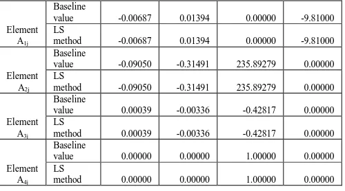
(5) The values of B747 base line parameters (base) and simulated parameters (LS) are given in Table 1 and found similar[22].
Table 1: Comparison of baseline parameter with estimated (LS) parameters.
Element A1j
Baseline
value -0.00687 0.01394 0.00000 -9.81000
LS
method -0.00687 0.01394 0.00000 -9.81000
Element A2j
Baseline
value -0.09050 -0.31491 235.89279 0.00000
LS
method -0.09050 -0.31491 235.89279 0.00000
Element A3j
Baseline
value 0.00039 -0.00336 -0.42817 0.00000
LS
method 0.00039 -0.00336 -0.42817 0.00000
Element A4j
Baseline
value 0.00000 0.00000 1.00000 0.00000
LS
method 0.00000 0.00000 1.00000 0.00000
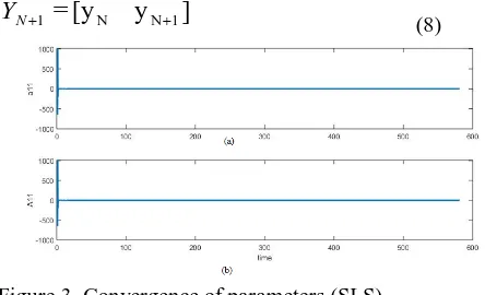
The sequential least square (SLS) parameter estimation is given in equation (6) where N denotes the Nth second of
experiment data [15]. The
x
,
x
of aircraft data is applied in Equation (7) and (8) to generate real time flight data. Then real time aircraft data is applied in Equation (6) to get real time parameter as shown in Figure 3. The results of SLS method is compared with LS method as given in Table 2.-1 1 N T 1 N T ! N 1 N
1 =(Y X )(X X )
N
(6) ] x [x= N N 1
1
N
X
[image:2.595.61.286.653.759.2]International Journal of Innovative Technology and Exploring Engineering (IJITEE) ISSN: 2278-3075, Volume-8 Issue-7, May, 2019
] y [y
= N N 1
1
N
Y
[image:3.595.315.548.49.173.2](8)
Figure 3. Convergence of parameters (SLS)
Table 2: Comparison of SLS, LS and baseline values of parameter
Base line value of A11
LS value of A11
SLS value of A11
(before 3sec)
SLS value of A11
(after 3s, A11)
-0.00687 -0.00687 0.23428 -0.00687
III. CONSTRUCTIONOFMRFDIFAULT
DIAGNOSISMETHOD
[image:3.595.58.280.55.190.2]MRFDI is developed by cloning the autopilot model as shown in Figure 4. The actual model is assumed to be a real aircraft and the reference model to be a mathematical model of real aircraft. The fault is simulated by injecting steady state error in elevator as shown in Figure 5 during 350 sec. The aircraft experiencing change in altitude from reference aircraft as shown in Figure 6.
Figure 4. Actual aircraft and reference aircraft for model reference system
Figure 5. Fault injection and deviation of elevator from reference value – actuator feedback
Figure 6. Aircraft altitude variation between reference and actual model due to fault injection at actuator
The MRFDI compares actuator feedback and aircraft parameters between reference model and actual model using logic given in Table 3.
Table 3. Fault diagnosis logic
Varia nce in Actuator Feedbac k
Vari ance in aircraft parame ter
Actu ator fault
Instru ment fault
Uncont rolled Disturba nce
1 0 0 1 0
1 1 1 0 0
0 1 0 0 1
0 0 0 0 0
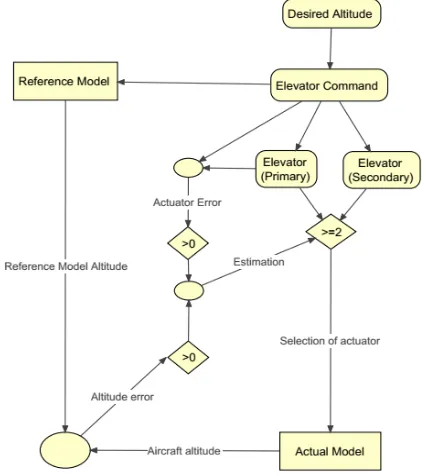
[image:3.595.307.546.248.371.2]The MRFDI uses fault diagnosis scheme shown in Figure 7. The MRFDI estimating variances in actuator feedback and parameter from model reference model and SLS method. The variance in actuator feedback shown in figure 5 and estimation of parameter variance is shown in figure 10. These variances are logically analysed as given in Table 3 and providing fault as flag value 0 and 1 as shown in Figure 7.
Figure 7. Fault diagnosis scheme for MRFDI
[image:3.595.90.250.446.605.2] [image:3.595.328.537.488.593.2]Similar to elevator fault injection, fault is injected at feedback instrument and aircraft output to observe MRFDI fault diagnosis.
IV. DEVELOPMENTOFFTFCBYEMBEDING
MRFDI
[image:4.595.320.533.96.334.2]The FTFC is developed by adding twin actuator as shown in Figure 8.
[image:4.595.61.286.183.297.2]Figure 8. FTFC construction by twin actuator Table 3. Fault Tolerant Flight Control – Control
allocation logic
The logic for FTFC function is given in Table 4 and implementation of MRFDI in FTFC is shown in Figure 9. The FTFC receives fault flag information from MRFDI as given in Table 3 by correlating variances in aircraft actuator and aircraft parameter. FTFC decides control allocation between primary and secondary actuator as given in Table 4. A fault in actuator induces variations in actuator feedback as well as aircraft parameters. So, the MRFDI sends protocol to FTFC as flag value 1 for actuator fault. Then FTFC allocates control to secondary actuator instead of primary actuator. A fault in actuator feedback instrument alters only feedback
value. So, FTFC retains control in primary actuator. An uncontrolled aircraft motion alters aircraft dynamics alone. So, FTFC retains control to primary actuator.
Figure 9. Implementation of MRFDI to FTFC
V. RESULTSANDDISCUSSION
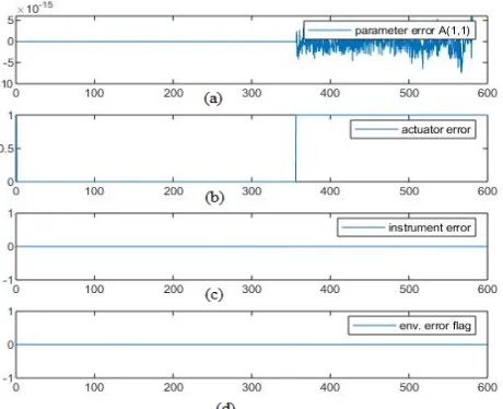
The fault diagnosis of MRFDI for actuator fault is shown in Figure 11. The MRFDI estimates variances in aircraft parameters as shown in Figure 10. A fault is injected at elevator actuator during 350 sec and parameters of actual and reference model is observed in Figure 10 (a) and (b). The variances in parameters is observed in Figure 10 (c) which confirms the variation in aircraft altitude deviation from its reference value.
Figure 10. Estimation of variance in aircraft parameter
[image:4.595.74.282.187.613.2] [image:4.595.96.201.336.632.2] [image:4.595.314.546.490.595.2]International Journal of Innovative Technology and Exploring Engineering (IJITEE) ISSN: 2278-3075, Volume-8 Issue-7, May, 2019
[image:5.595.318.544.54.196.2]Figure 11. MRFDI fault diagnosis for actuator fault
Figure 12. MRFDI fault diagnosis for actuator feedback instrument fault
Similarly, fault is injected to actuator feedback instrument and variances of aircraft parameters and actuator feedback was observed. The variation of aircraft parameter is shown in Figure 12(a). A fault in feedback instrument initially estimates fault flag value 1 for actuator as shown in Figure 12 (b). Then, as given in logic Table 3, MRFDI correlates both and estimating fault flag value 1 for instrument fault as shown in Figure 12 (c) and environment error as flag value 0 as shown in Figure 12 (c).
The uncontrolled aircraft motion is simulated as wind gust by adding fault in aircraft velocity. The change in parameters were observed as shown in figure 13 (a). Since aircraft actuator have working good as shown in Figure 13 (b), MRFDI estimates fault in environmental error as shown in Figure 13 (d).
Figure 13. MRFDI fault diagnosis for uncontrolled aircraft motion
FTFC for actuator fault case develops control allocation signal to secondary actuator as shown in Figure 14. It is observed that FTFC allocating control to secondary actuator during malfunction primary actuator as given in Table 4. FTFC recovers aircraft altitude as shown in Figure 15.
[image:5.595.59.288.267.475.2] [image:5.595.311.548.302.389.2]Figure 14. Control reallocation to secondary actuator during malfunction in primary actuator
Figure 15. FTFC function during primary actuator fault – recovery of aircraft altitude
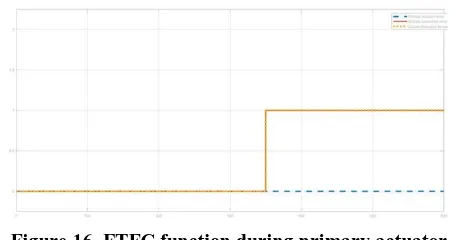
[image:5.595.320.546.418.551.2] [image:5.595.315.544.597.708.2]Similarly, FTFC is retaining control in primary actuator for instrument fault and environment fault as shown in Figure 16 and 17.
Figure 15. FTFC function during primary actuator fault – retention of primary actuator during instrument
Figure 16. FTFC function during primary actuator fault – retention of primary actuator during uncontrolled
aircraft motion
VI. CONCLUSION
MRFDI is tested for fault diagnosis of actuator fault, instrument error and environmental uncertainty. Results reveals that MRFDI is correlating variances in actuator feedback and aircraft parameter for robust fault diagnosis. FTFC is developed by incorporating twin actuator configuration and embedded with MRFDI. MRFDI injects protocol to FTFC to allocate control among primary and secondary actuator. FTFC is successfully allocating control to secondary actuator during occurrence of fault in actuator. The proposed fault diagnosis methodology demonstrates the ability to classify different fault sources existed in the aircraft. The future work is to implement system identification to prototype aircraft and test functionality of MRFDI and FTFC.
REFERENCES
1. Girish Chowdhary, Eric N. Johnson, Rajeev Chandramohan, M. Scott Kimbrell, and Anthony Calise, Guidance and Control of Airplanes Under Actuator Failures and Severe Structural Damage,Journal of guidance, control, and dynamics, Vol. 36, No. 4, July–August 2013
2. Girish Chowdhary, Wesley M. DeBusk, and Eric N. Johnson, Real-Time System Identification of a Small Multi-Engine Aircraft with Structural Damage, AIAA Infotech@Aerospace 2010, 20 - 22 April 2010, Atlanta, Georgia
3. Damien B. Jourdan, Michael D. Piedmonte, Vlad Gavriletsy, and David W. VosEnhancing, UAV Survivability Through Damage Tolerant Control, AIAA Guidance, Navigation, and Control Conference, 2 - 5 August 2010, Toronto, Ontario Canada
4. Wang Xingjian, Wang Shaoping, Yang Zhongwei, Zhang Chao, Active fault-tolerant control strategy of large civil aircraft under elevator failures, Chinese journal of aeronautics, 2015
5. Dinesh D. Dhadekar, S. E. Talole, Robust Fault Tolerant Longitudinal Aircraft Control, IFAC PapersOnLine 51-1 (2018) 604–609
6. Youmin Zhang, Jin Jiang, Bibliographical review on reconfigurable fault-tolerant control systems, 5th IFAC Symposium on Fault detection,
supervision and safety for technical processes, 2003
7. Yu Xiang, Zhang Youmin, Design of passive fault-tolerant flight controller against actuator failures, Chinese journal of aeronautics, 2015 8. Wang Jun, Wang Shaoping, Wang Xingjian, Shi Cun, Mileta M. Tomovic, Active fault tolerant control for vertical tail damaged aircraft with dissimilar redundantactuation system, Chinese journal of aeronautics, 2016
9. Liang QU, Yinghui LI, Haojun XU, Dengcheng ZHANG, Guoqiang YUAN, Aircraft nonlinear stability analysis and multidimensional stability region estimation under icing conditions, Chinese journal of aeronautics, 2017
10. Xiaoliang WANG, Changle XIANG, Homayoun NAJJARAN, Bin XU, Robust adaptive fault-tolerant control of a tandem coaxial ducted fan aircraft with actuator saturation, Chinese journal of aeronautics, 2018 11. Rudaba Khan, Paul Williams, Paul Riseborough, Asha Rao, and Robin
Hill, Active Fault Tolerant Flight Control System Design,
12. O.N. Korsuna, M.H. Omb, K.Z. Lattb, A.V. Stulovskii, Real-time aerodynamic parameter identification for the purpose of aircraft intelligent technical state monitoring, Procedia Computer Science 103 ( 2017 ) 67 – 74
13. O.N. Korsuna,, B.K. Poplavsky, S.Ju. Prihodko, Intelligent support for aircraft flight test data processing in problem of engine thrust estimation, Procedia Computer Science 103 ( 2017 ) 82 – 87
14. Andrei Dorobantu, Austin Murch, Bérénice Mettler, and Gary Balas, System Identification for Small, Low-Cost, Fixed-Wing Unmanned Aircraft, https://arc.aiaa.org/doi/10.2514/1.C032065
15. A. Grauer, Parameter Uncertainty for Aircraft Aerodynamic Modeling using Recursive Least Squares, AIAA Atmospheric Flight Mechanics Conference, AIAA SciTech Forum, (AIAA 2016-2009)
https://doi.org/10.2514/6.2016-2009
16. Harald Pfifer and Brian P. Danowsky, System Identification of a Small Flexible Aircraft - Invited, AIAA Atmospheric Flight Mechanics Conference, AIAA SciTech Forum, (AIAA 2016-1750) ,
https://doi.org/10.2514/6.2016-1750
17. Damien B. Jourdan, Michael D. Piedmonte, Vlad Gavriletsy, and David W. VosEnhancing, UAV Survivability Through Damage Tolerant Control, AIAA Guidance, Navigation, and Control Conference, 2 - 5 August 2010, Toronto, Ontario Canada
18. Robert C. Nelson, Flight stability and automatic control, McGraw-Hill Ryerson, Limited, 1989
19. Bernard Etkin, Lloyd Duff Reid, Dynamics of Flight: Stability and Control, 3rd Edition, JOHN WILEY & SONS, INC
20. Jategaonkar, R., Flight Vehicle System Identification, AIAA, 2006
21. Nawel Bayar, Saber Darmoul, Sonia Hajri-Gabouj, Henri Pierreval, Fault detection, diagnosis and recovery using Artificial Immune Systems: A review, Engineering Applications of Artificial Intelligence 46 (2015) 43–57
22. Jaganraj, R., and Velu, R., (2018), “Robust model reference fault detection and identification system for fixed wing aircrafts”, International Journal of Vehicle Structures and Systems, Vol. 10(5). pp. 371−376. doi: 10.4273/ijvss.10.5.14
AUTHORSPROFILE
Mr.R.Jaganraj is a research scholar of Aeronautical Engineering Department in Vel Tech Rangarajan Dr.Sagunthala R&D Institute of Science and Technology. He has 5 years of teaching, research and industrial experience. His current research focuses on unmanned aerial systems, fault tolerant control and autonomous drones.