International Journal of Innovative Technology and Exploring Engineering (IJITEE) ISSN: 2278-3075, Volume-8 Issue-12, October 2019
Abstract: This paper deals with the experimental investigation and testing on a single point cutting tool with carbide inserts and high speed steel tool. Cutting tool has to be strong enough to withstand the wear resistance. It is to be proved that carbide inserts have better performance than HSS tools on machining operation. Components with higher surface quality, higher material removal rate in less time and lower tool wear is only possible by carbide insert tools. The tool material selected for this experiment are cemented & tungsten carbide inserts along with high speed steel tool on machining medium carbon steel EN19. The complete machining process is performed on cnc lathe machine Hence the intention of this project is to minimize the surface roughness, tool wear, machining time and increasing the material removal rate. Taguchi’s L9 orthogonal array is favor for this investigation work. The result obtained in this project can be further used for optimizing the process parameters there by optimized results helps the operator to improve the quality as well as production rate.
Keywords: Single point Cutting tool, carbide inserts, HSS, surface roughness, MRR, Tool wear and Tool life.
I. INTRODUCTION
Machining process is one of the metal removal process in which the unwanted substance from the work piece is detached by cutting tool in the type of chips. The cutting tool rake angle plays an important role in surface finish also wear. Heat is generated at the tip of the tool during the machining process that affects the tool geometry and properties. Therefore, proper material selection with accurate rake angles is provided to tool in order to overcome the failure of tool. It is also determined that any sudden change in cutting speed, cutting depth & feed rate has the maximum cause on increasing cutting temperature, wear as well as surface unevenness.
Hence any improvement in tool life will have a direct impact on the cost of production. The cutting tool geometry includes back rake angle, end relief angle, side cutting edge angle, end cutting edge angle, lip angle, side rake angle and side relief angle.
Revised Manuscript Received on October 05, 2019.
* Correspondence Author
A Kriyadeesh* studying M.tech in Mechanical Engineering, Institute of Aeronautical Engineering, Dundigal, Hyderabad.
Email : [email protected]
Dr.P.Srinivas Rao, Department of Mechanical Engineering. Institute of Aeronautical Engineering, Dundigal, Hyderabad.
Email:[email protected]
C. Labesh kumar, Department of Mechanical Engineering, Institute of Aeronautical Engineering, Dundigal, Hyderabad.
Email: [email protected]
During machining operation enormous amount of heat and resistance is developed among tool and work piece. Coolant supplying during the machining operation is also plays an important role to overcome the tool failure and it acts an lubricant.
II. OBJECTIVES
To determine the optimum surface finishing of work piece by varying the cutting parameters.
To maximize the material removal rate (MRR) with in less machining time. It helps to increase the production rate.
In order to reduce the tools wear without failure such that tool life increases.
III. EXPERIMENTAL DETAILS A. Selection of tool material
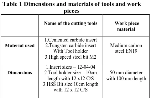
[image:1.595.312.553.505.662.2]In this investigation the carbide inserts material used are Cemented and Tungsten carbide inserts with tool holder PCLNL 12x12 H12 WIDAX and also High-speed steel M2 is selected for machining. The complete investigation is done on CNC lathe machine. The dimensions of tools and work pieces are tabulated below.
Table 1 Dimensions and materials of tools and work pieces
Name of the cutting tools Work piece material
Material used
1.Cemented carbide insert 2.Tungsten carbide insert
With Tool holder 3.High speed steel bit M2
Medium carbon steel EN19
Dimensions
1.Insert sizes – 12-04-04 2.Tool holder size – 10cm
length with 12 x12 C/S 3.HSS Bit size 10cm length
with 12 x 12 C/S
50 mm diameter with 100 mm length
Optimization of Input Parameters with Carbide
Inserts and HSS Tool on CNC Turning of EN19
Steel
Fig 1. Different cutting tools B. Selection of work piece material
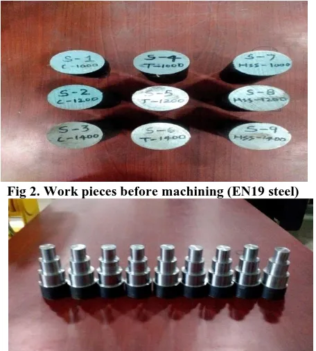
[image:2.595.55.287.51.196.2]The work piece substance preferred for this experimental investigation is Medium carbon steel EN19. It is also designated in AISI 4140 alloy steel. EN19 steel is most widely available in market and industries. The demand for this material is more in many sectors because it has wide spread application in automobile parts, gears, spindles, shafts, axles, bolts, pinions, and also in machinery equipment. The raw material selected is in the form of rods with dimension 50 mm diameter and 100 mm length.
Fig 2. Work pieces before machining (EN19 steel)
Fig 3. Work pieces after machining (EN19 Steel) AISI 4140 alloy steel be heated at 8450C and quenched in oil. Before is hardened it is normalized by heating at 9130C for a long time. It is hot worked at 816 to 10380C. The composition of medium carbon steel EN19 is presented in below table.
IV. EXPERIMENTAL UNIT
The practical experiment is conducted on CNC lathe turning center on EN19 medium carbon steel. All the trials are conducted with varying cutting factors like cutting depth feed rate and spindle speed respectively. The below fig represent the machining operation on CNC turning lathe as follows.
Fig 4. Experimental unit 3.1 Surface roughness measurement
[image:2.595.308.541.311.487.2]Roughness can be checked by physical judgment beside a "surface roughness comparator" a trial of known surface unevenness.Surface unevenness often summarized to roughness, is a component of surface texture.. If these abnormalities are large, the surface is irregular; if they are slight, the surface is level.
Fig 5. surface roughness tester
V. EXPERIMENTAL RESULTS
[image:2.595.58.286.332.585.2]International Journal of Innovative Technology and Exploring Engineering (IJITEE) ISSN: 2278-3075, Volume-8 Issue-12, October 2019
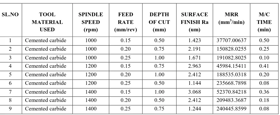
Table 2 Cemented carbide insert tool experimental results
SL.NO TOOL
MATERIAL USED
SPINDLE SPEED
(rpm)
FEED RATE (mm/rev)
DEPTH OF CUT (mm)
SURFACE FINISH Ra
(um)
MRR (mm3/min)
M/C TIME
(min)
1 Cemented carbide 1000 0.15 0.50 1.423 37707.00637 0.50
2 Cemented carbide 1000 0.20 0.75 2.191 150828.0255 0.25
3 Cemented carbide 1000 0.25 1.00 1.671 191082.8025 0.10
4 Cemented carbide 1200 0.15 0.75 2.963 45984.15411 0.41
5 Cemented carbide 1200 0.20 1.00 2.412 188535.0318 0.20
6 Cemented carbide 1200 0.25 0.50 1.144 235668.7898 0.08
7 Cemented carbide 1400 0.15 1.00 3.068 52370.84218 0.36
8 Cemented carbide 1400 0.20 0.50 2.412 209483.3687 0.18
9 Cemented carbide 1400 0.25 0.75 1.244 240445.8599 0.08
Table 3 Tungsten carbide insert tool experimental results
SL.NO TOOL
MATERIAL USED
SPINDLE SPEED
(rpm)
FEED RATE (mm/rev)
DEPTH OF CUT (mm)
SURFACE FINISH Ra
(um)
MRR (mm3/min)
M/C TIME
(min)
1 Tungsten carbide 1000 0.15 0.50 3.882 37197.45223 0.50
2 Tungsten carbide 1000 0.20 0.75 2.944 149808.9172 0.25
3 Tungsten carbide 1000 0.25 1.00 1.638 196178.3439 0.10
4 Tungsten carbide 1200 0.15 0.75 2.908 44889.2933 0.42
5 Tungsten carbide 1200 0.20 1.00 2.249 179557.1732 0.21
6 Tungsten carbide 1200 0.25 0.50 2.387 170237.4059 0.11
7 Tungsten carbide 1400 0.15 1.00 2.892 51309.27105 0.36
8 Tungsten carbide 1400 0.20 0.50 2.338 210898.7969 0.18
[image:3.595.52.549.299.513.2]9 Tungsten carbide 1400 0.25 0.75 0.905 234076.4331 0.08
Table 4 High speed steel tool experimental results
SL.NO TOOL
MATERIAL USED
SPINDLE SPEED
(rpm)
FEED RATE (mm/rev)
DEPTH OF CUT (mm)
SURFACE FINISH Ra
(um)
MRR (mm3/min)
M/C TIME
(min)
1 HSS 1000 0.15 0.50 1.640 37197.45223 0.50
2 HSS 1000 0.20 0.75 2.770 150318.4713 0.25
3 HSS 1000 0.25 1.00 1.844 194904.4586 0.10
4 HSS 1200 0.15 0.75 0.916 44889.2933 0.42
5 HSS 1200 0.20 1.00 2.225 178343.9490 0.21
6 HSS 1200 0.25 0.50 1.512 219391.3659 0.09
7 HSS 1400 0.15 1.00 4.415 52370.84218 0.36
8 HSS 1400 0.20 0.50 4.050 211606.5111 0.18
VI. RESULT AND DISCUSSION
6. ANALYSIS OF VARIANCE (ANOVA)
6.1 Statistical analysis of surface roughness for cemented carbide tool
It indicates that feed rate is the most important factor for
surface roughness which has p- value of 0.228. Statistical ANOVA is shown in below table 5.
Table 5 surface unevenness ANOVA table
Basis DF Adj SS Adj MS F-Value P-Value
Spindle speed
2 0.4039 0.2020 0.60 0.624
Feed rate 2 2.2730 1.1365 3.39 0.228
Cutting depth
2 0.8109 0.4055 1.21 0.453
fault 2 0.6706 0.3353 - -
Total 8 4.1584 - - -
[image:4.595.327.528.51.196.2]The interaction plot as shown in the figure examines that as the speed and feed increases surface roughness rises so as the feed and cutting depth reduces surface unevenness decreases.
Fig 6. Surface unevenness Interaction plot
6.2 Statistical analysis of surface roughness for tungsten carbide tool
Table 6 ANOVA table for surface unevenness
Basis DF Adj SS Adj MS F-Value
P-Valu e
Spindle speed
2.0 0.9101 0.4551 2.52 0.284
Feed rate
2.0 3.7912 1.8956 10.48 0.087
Cutting depth
2.0 0.7557 0.3778 2.09 0.324
fault 2.0 0.3617 0.1808 -
-Total 8 5.8186 - -
-Fig 7. Surface unevenness Interaction plot
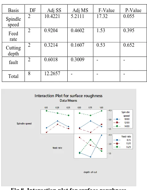
6.3 Statistical analysis of surface roughness for High Speed steel tool
Table 7 surface unevenness ANOVA table
Basis DF Adj SS Adj MS F-Value P-Value
Spindle speed
2 10.4221 5.2111 17.32 0.055
Feed rate
2 0.9204 0.4602 1.53 0.395
Cutting depth
2 0.3214 0.1607 0.53 0.652
fault 2 0.6018 0.3009 -
-Total 8 12.2657 - -
-Fig 8. Interaction plot for surface roughness 6.4 Statistical analysis of MRR for cemented carbide tool
It indicates that all the cutting parameters like spindle speed, feed rate and cutting depth are the significant factors. Statistical ANOVA is shown in below table.
Table 8 ANOVA table for MRR
Basis DF Adj SS Adj MS F-Value P-Value
Spindle speed
2 2673248455 13366242
28
17.33 0.055
Feed rate 2 51545873934 25772936
967
334.11 0.003
Cutting depth
2 479683217 23984160
9
3.11 0.243
fault 2 154280294 77140147 - -
[image:4.595.315.554.257.564.2] [image:4.595.80.261.366.504.2]International Journal of Innovative Technology and Exploring Engineering (IJITEE) ISSN: 2278-3075, Volume-8 Issue-12, October 2019
It is also observed that increasing amount of cutting depth increases the metal removal rate .The interaction plot is shown in below figure.
Fig 9. MRR Interaction plot
[image:5.595.311.542.44.278.2]6.5 Statistical analysis of MRR for tungsten carbide tool
Table 9 ANOVA table for MRR
Basis DF Adj SS Adj MS F-Value P-Value
Spindle speed
2 2582942269 1291471
134
1.81 0.355
Feed rate
2 4303871483 2151935
741
30.22 0.032
Cutting depth
2 20876721 1043836
1
0.01 0.986
fault 2 1423971789 7119858
94
- -
[image:5.595.64.277.89.247.2]Total 8 4706650560 - - -
Fig 10. MRR Interaction plot
6.6 Statistical analysis of MRR for High speed steel tool
Table 10 ANOVA table for MRR
Basis DF Adj SS Adj MS F-Value
P-Valu e
Spind le speed
2 1886875363 943437682 12.95 0.072
Feed rate
2 4764159254
2
2382079627 1
326.92 0.003
Cutti 2 466254185 233127093 3.20 0.238
ng depth
fault 2 145727178 72863589 - -
Total 8 5014044926
8
[image:5.595.50.287.318.644.2]- - -
Fig 11. Interaction plot for MRR
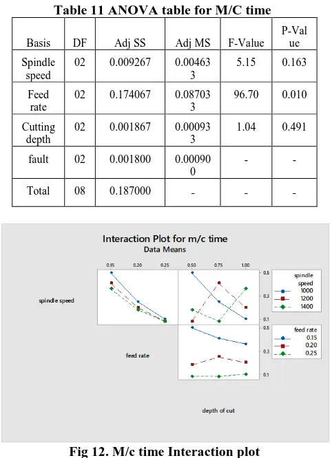
6.7 Statistical analysis of machining time for cemented carbide tool
It indicates that as the spindle speed and cutting depth increases machining time decreases. The table for statistical analysis is shown in below.
Table 11 ANOVA table for M/C time
Basis DF Adj SS Adj MS F-Value
P-Val ue
Spindle speed
02 0.009267 0.00463
3
5.15 0.163
Feed rate
02 0.174067 0.08703
3
96.70 0.010
Cutting depth
02 0.001867 0.00093
3
1.04 0.491
fault 02 0.001800 0.00090
0
- -
Total 08 0.187000 - - -
Fig 12. M/c time Interaction plot
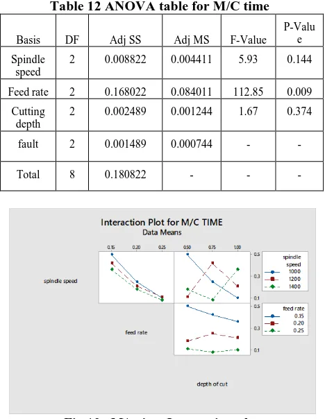
[image:5.595.307.548.343.676.2]Table 12 ANOVA table for M/C time
Basis DF Adj SS Adj MS F-Value
P-Valu e
Spindle speed
2 0.008822 0.004411 5.93 0.144
Feed rate 2 0.168022 0.084011 112.85 0.009
Cutting depth
2 0.002489 0.001244 1.67 0.374
fault 2 0.001489 0.000744 - -
Total 8 0.180822 - - -
Fig 13. M/c time Interaction plot
6.9 Statistical analysis of Machining time for High speed steel tool
Table 13 ANOVA for M/C time
Basis DF Adj SS Adj MS F-Value P-Value
Spindl e speed
2 0.008867 0.004433 4.93 0.169
Feed rate
2 0.174067 0.087033 96.70 0.010
Cuttin g depth
2 0.001867 0.000933 1.04 0.491
fault 2 0.001800 0.000900 - -
[image:6.595.54.287.406.727.2]Total 8 0.186600 - - -
Fig 14. Interaction plot for M/C time
VII. CONCLUSION
The following are the conclusions drawn after conducting the experimental investigation with three different tool materials with varying cutting parameters to optimize the
results. From the analysis of results the signal to noise ratio (S/N) approach, taguchi’s minimization technique and Analysis of variance (ANOVA) the following conclusions are obtained
The surface finishing is mainly affected by feed rate and cutting depth. If the feed rate increases the surface roughness increases gradually.
If spindle speed, feed rate and cutting depth gradually increases the metal removal rate also increases.
The optimum values for surface finish (1.144 µm) for cemented carbide insert as follows
i) Spindle speed - 1200 rev per min ii) Feed rate - 0.25 mm/rev iii) Depth of cut - 0.50 mm
The optimum values for surface finish (0.905 µm) for tungsten carbide insert as follows.
i) Spindle speed - 1400 rev per min ii) Feed rate - 0.25 mm/rev iii) Depth of cut - 0.75 mm
The optimum values for surface finish (0.196 µm) for High speed steel as follows
i) Spindle speed - 1200 rev per min ii) Feed rate - 0.15 mm/rev iii) Depth of cut - 0.75 mm
Tungsten carbide insert undergoes more tool wear when compared to cemented carbide insert.
The outcomes of ANOVA and Taguchi technique illustrates that feed rate is more essential factor which damages the surface finishing and tool wear.
For getting the optimum level of MRR the spindle speed should be high i.e. 1400 rpm, feed rate should also high i.e. 0.25 mm/rev and cutting depth should also high i.e.1.00mm.
REFERENCES
1. Yuvaraj p. Ballal, Manjit m. khade, Comparison of performance of coated carbide inserts with uncoated carbide inserts in turning gray cast iron, International journal of mechanical Engineering and Technology, Volume 4, Issue 2, March-April (2013), pp, 392-400.
2. Prabhat kumar Sinha, ManasTiwari, Optimization of Input parameters of CNC turning operation for the given component using taguchi approach, International journal of Mechanical Engineering and Technology, Volume 4, Issue 4, July-Aug (2013), pp, 188-196. 3. S.S Acharya, R.L.Karwande, Investigation and Optimization of turning
process parameter in wet and MQL system on EN31, International journal of Mechanical Engineering and Technology, Volume 5, Issue 7, July (2014), pp, 134-143.
4. Sachin c Borse, Optimization of Turning process parameter in dry turning of SAE 52100 steel, International journal of Mechanical Engineering and Technology, Volume 5, Issue 12, December (2014), pp, 01-08.
5. V.Baskaran, S. Prakash, Experimental investigation of Machining parameters in Cnc turning EN8 steel by Taguchi design of Experiments, APRN journal of Engineering & Applied sciences, Volume 12, no, 20, October 2017.
6. Kishan Dhameliya, Jignesh Desai, Experimental Investigation of process parameters on MRR and surface roughness in Turning operation on Cnc lathe machine for mild steel E250:IS 2062, International journal of Engineering research & Technology, Volume-3, issue 5, May-2014, ISSN: 2278-0181.
7. K.G. Nikam, S.V Vanjari, Experimental investigation on surface roughness on finish turning of EN8 steel, International journal of science and Research, volume 4, Issue 3, March-2015, ISSN: 2319-7064.
8. Mohd shadab Siddique, MohdNehalaktar, Turning parameter optimization for material removal rate of AISI 4140 alloy steel by Taguchi method, international Journal of Engineering and technology, Volume:04, Issue:06, June-2017,
International Journal of Innovative Technology and Exploring Engineering (IJITEE) ISSN: 2278-3075, Volume-8 Issue-12, October 2019
9. Robin sharma, DrHarionsharma, Comparative performance study of turning operation of CNC turning center, International Journal of Innovative research in Advanced Engineering, Volume 3, Issue 04, April 2016, ISSN: 2349-2763.
10. Krupalpawar, Raj kumarpalhade, Comparative performance Analysis of insert geometry by CNC turning of HSS (M2) and Taguchi method, International Journal of Research in Advent Technology ICATEST 2015, 08 march 2015, ISSN; 2321-9637.
11. Sayak Mukherjee, Anurag Kamal, Optimization of Material removal rate during turning of SAE1020 material in Cnc lathe using Taguchi Technique, 12th global congress on manufacturing and management Gcmm 2014.
12. U.Pradeep Kumar, C Fackrunisha, Experimental Investigation of optimizing EN8 and EN19 steels using cryogenic Technique with Ansys results, IOSR journal of Mechanical and civil Engineering, volume 15, Issue 4, July-Aug 2018, pp.44-84, ISSN: 2278-1684. 13. CH. Siva Rama Krishna, Karanam Krishna, Experimental
Investigation and Analysis of cutting parameters in CNC turning on Aluminum, International Journal of Engineering Technology, management and Applied sciences, Volume 3, Issue 1, January 2015, ISSN: 2349-4476.
14. Diptikanta Das, Anil kumarchanbey, Investigation cutting tool wear in turning Al 7075/Sicp metal matrix composite, International Conference on Mechanical materials & Renewable energy 2018, IOP conference series
AUTHORS PROFILE
A KRIYADEESH currently pursuing M.Tech in Mechanical Engineering at Institute of Aeronautical Engineering, Dundigal, Hyderabad. He obtained B.Tech in mechanical engineering from Vijay rural Engineering College Nizamabad, India. Email: [email protected]
DR. P SRINIVAS RAO, Working as professor in the Department of Mechanical engineering, Institute of Aeronautical Engineering, Dundigal, Hyderabad. He has published papers in International and National journals and Conferences.
Email:[email protected]
C.LABESH KUMAR, Working in the Department of Mechanical Engineering, Institute of Aeronautical engineering, Dundigal. Hyderabad. He has 9 years of teaching experience and published papers in International and National journals and Conferences. His area of research is computer aided design and manufacturing.