Abstract: Flow forming is an emerging process being widely used for manufacturing axisymmetric components that are used in the aerospace industry and automobile industries. In the present investigation, the mechanical response of the Al6101 T6 workpiece to the flow forming process has been studied. The study showed that the microhardness of the preform increased by 20.2% higher at 60% thickness reduction as compared to hardness value at 10% thickness reduction. A linear relation between the hardness variation and thickness reduction has been proposed based on experimental data. The internal diameter was found to increase with increase in the thickness reduction. In the present investigation, a 3mm increase in diameter was seen in the 120mm length.
Keywords: Al6101 T6, Flow forming, Hardness variation, Thickness reduction.
I. INTRODUCTION
Flow forming is a cold working process that is used to produce axisymmetric products like tubes, wheel drum in automobiles, drives shafts, hydraulic cylinders, cones and nozzles in aerospace industries. It is now also used for manufacturing casing for missiles.
Flow forming is a type of near-net engineering process that, in general, avoids any further machining process. A flow formed product generally has superior mechanical properties than the work material or preform owing to its cold working nature. Flow forming is a versatile process and is used to produce a large reduction in cold working conditions. The process is not limited to soft metals like aluminum but it is equally applicable to hard to deform metals like niobium, steel, tungsten, Inconel, etc.
Many researchers have used different techniques such as experimental, analytical and computational techniques to study the response of flow formed products. Kalpakjian and Rajagopal [1] studied the spinning of tubes which gave insight about the flow forming process and showed that flow forming and spinning processes are kinematically similar. The mechanics of flow forming was studied in detail by Bennich [2] and presented a physical model and predicted the microstructure evolution during the process.
Revised Manuscript Received on December 05, 2019.
Ashutosh Kumar Srivastwa*, Department of Mechanical Engg, Indian Institute of Technology (BHU) Varanasi, India. Email:
ashutosh.rs.mec14@itbhu.ac.in.
Santosh Kumar, Department of Mechanical Engg, Indian Institute of Technology (BHU) Varanasi, India. Email: Santosh.kumar.mec@iitbhu.ac.in.
Pankaj Kumar Singh, Department of Mechanical Engg, Indian Institute of Technology (BHU) Varanasi, India. Email:
pankaj.krsingh.rs.mec18@itbhu.ac.in.
Kalpakcioglu [3] studied the spinning process of work hardenable alloys (Al
6XXX alloys, Cu, mild steel) and suggested that the limit of formability should be determined experimentally for each material. Ma [4] studied the optimal angle of attack for the tooling for which the power required in tube spinning is minimum. Slater [5] did experimental and analytical investigations to determine the flow forming forces and forming limits during the spinning process.
Gur and Tirosh [6] calculated the power consumption during the flow forminsg process using the upper bound method. They considered plain strain condition with shear strain only in longitudinal and transverse direction. Park et. al [7] used the upper bound technique to calculate the total power and tangential force assuming only longitudinal strain. Kemin et al. [8] used experimental and elasto- plastic finite element analysis to predict the diametral growth in tube spinning. Roy et. al. [9] studied the evolution of plastic strain during the flow forming process using FEM techniques and experimental analysis. Roy and Maijer [10] analyzed the contact surface between the tool and workpiece and proposed a model to predict the contact area for all tooling geometries. Wong et. al [11] studied the flow of material in tube spinning with roller path and roller geometry as the controlling variable. Haghsenas and Klassen [12] compared the mechanical and metallurgical response of different FCC metals (Al6061, Al5052, pure copper and brass (70/30). Mohebbi and Akbarzadeh [13] studied the redundant strains generated during the flow forming process using ABAQUS. Jahazi and Ebrahami [14] studied the effect of process parameters such as feed rate, roller attack angle and percentage deformation on the spinnability of the preform. Davidson et. al. [15] studied the percentage elongation of AA6061 tube and correlated and proposed the percentage elongation as a function of feed rate, speed of mandrel and in feed depth. Srinivasulu et.al. [16] studied the variation of mean diameter during flow forming of AA6085 using the DOE approach. Molladavoudi and Djavanroodi [17] studied the thickness reduction effect on the properties of Al7075-O during the flow forming process.
Although many researchers had focused on the flow forming of different aluminium grades, there is hardly any work on flow forming of Al6101 T6 in the knowledge of the author. In the present investigation, the effect of thickness reduction on the diametral growth and the variation of microhardness values at different thickness reduction have been studied.
Diametral Growth and Hardness Variation in
Al6101 T6 during Flow Forming
II. EXPERIMENTALSETUP
A. Flow forming process
The flow forming involves the forming of the workpiece by a roller or a set of rollers. The workpiece or preform is a hollow tube and is mounted on the mandrel. The material of mandrel is chosen such that it should not deform under the loading condition. When the roller moves in the longitudinal direction, it compresses the material and at the same time, due to axial motion, it stretches the material in the material in the longitudinal direction. Thus the material gets deformed. According to the principle of constancy of volume, the total volume remains constant in the metal deformation. Therefore, the material gets elongated as the thickness gets reduced. In principle, the flow forming process can be regarded as a modified spinning process. Based on the direction of material flow to the direction of longitudinal movement of roller, the flow forming operation can be classified as forward flow forming and backward or reverse flow forming process. If the direction of the flow of material is parallel to the direction of roller direction in the axial direction, then the process is called a forward flow forming process. Similarly, if the direction of flow of material and roller direction motion is antiparallel, then the process is called as backward or reverse flow forming. Fig. 1 (a) and (b) show the schematic diagram of the forward and backward flow forming respectively.
(a)
(b)
Fig. 1. (a) Schematic diagram of the forward flow forming process (b) schematic diagram of reverse flow
forming process B. Experimental setup
[image:2.595.313.573.241.397.2]The experimentation was carried on NH22 lathe machine. Fig. 2 shows the experimental setup used in the investigation. The workpiece material was Al6101T6 alloy. The inner diameter of the preform was 63mm while the thickness of the preform was 2 mm. The mandrel was made from SAE 4340. The outer diameter was kept at 62.9 mm. A roller assembly was fabricated with the roller of diameter 63mm. The attack angle was maintained at 30° and the relief angle was also 30°. The roller assembly was mounted on the tool post of the lathe. The mandrel was mounted in the headstock. The workpiece was mounted on the mandrel. The mandrel was rotated at 400 rpm. The longitudinal feed was 0.4mm/rev.
Fig. 2. Flow forming setup C. Experimental conditions
[image:2.595.50.291.453.762.2]The preform taken in the present investigation was Al6101 T6. The chemical composition of the preform is given in table- I. The material was supplied in the form of a hollow tube by M/s Hindalco. The preform was machined to the design dimension shown in fig. 3.
Fig. 3. Schematic diagram of preform
The design of the preform consisted of a small rest of 7 mm at the end was given to hold the preform on the mandrel. The thickness of the rest should be thick enough so that there should be negligible deformation in this region on the application of roller load. A small amount of chamfer of 30° (equal to attack angle) was incorporated to ensure smooth contact of roller at the start. Further, the chamfer also reduces the material flow in the backward direction when the roller load is applied. The initial thickness was maintained at 2mm. To study the effect of
[image:2.595.318.522.490.616.2]constant in- feed of 0.1mm was given.
Table- I: Chemical compositions of Al6101
Si Fe Mn Mg Cu
0.499 0.146 0.0021 0.580 <0.0004
Ti Cr Zn V Al
0.0132 0.0014 0.0023 0.0080 98.7
The total length of the preform was taken to be 52 mm but the total length of the preform that took part in the flow forming process was 45mm (excluding the thickness of rest). The flow form length reported in the present investigation also excludes the rest thickness.
Table- II: Flow forming process parameters
Preform Dimensions
Inner diameter(mm) 63
Wall thickness(mm) 2.0
Initial length(mm) 45
Roller Dimensions
Diameter(mm) 63
Attack angle 30°
Relief angle (Smoothening angle)
30°
Feed rate(mm/rev) 0.04
Process Parameters
Reduction(%) per pass 10,20,40,50,60
Speed of rotation(rpm) 420
III. RESULTANDDISCUSSION
The flow formed product and a preform is shown in figure 4. A multi-pass stepped product was produced by changing the extent of the in-feed of the roller. The region 1E denotes the minimum thickness reduction zone first pass while IA denotes the thickness reduction in the last pass. The regions 1E,1D,1C,1B and 1A denotes the various regions obtained in first, second, third, fourth and fifth pass.
A. Thickness measurement
[image:3.595.309.545.117.227.2]The thickness values and the thickness reduction per pass after each pass in different regions are shown in table- III. The maximum reduction was 60% that was achieved in 5 passes. The in-feed values were given as 0.1 mm for the first two passes, 0.2mm in 3rd pass and 0.1mm in the last two passes.
Fig. 4. Flow formed product and the preform
Table- III: Thickness values in different regions
Region of flow formed product
Thickness reduction(m
m)
% reduction per pass
Cumulative % reduction
1E 1.8 10 10
1D 1.6 11.11 20
1C 1.2 25 40
1B 1.0 16.67 50
1A 0.8 20 60
B. Diametral growth
The average diametrical growth was found to be around 3 mm in 120 mm of flow formed sample. The increase in internal diameter had been reported by Song et.al. [18]. According to them, the increase in internal diameter approximately followed an 'S' shaped curve. The increase in internal diameter can be explained based on the elastic recovery of the material after the deformation is complete. As the flow forming involves compressing the material below the roller, a spring back is observed when the process is complete. This increase is more at the end of the process in the flow-forming product.
C. Hardness variation
The microhardness of the preform and flow formed product was measured on Vicker micro hardness tester (model –
SEMIAUTOMATIC, serial no.-104, MICROMACH
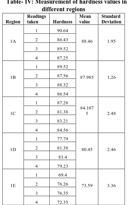
[image:3.595.66.271.577.772.2]Technologies, Pune) Vicker diamond indenter at an applied of 50g for a dwell time of 10 s. The hardness values in different regions are shown in table 4. The measured hardness showed a continuous increase with an increase in thickness reduction. The average hardness increased by 73.59 HRC in region 1E to 88.46 HRC in region 1A. Figure 3 shows the variation of hardness values with cumulative thickness reduction. The increase in hardness can be explained based on strain hardening. As thickness reduction increases per pass, the amount of plastic strain increases and therefore the workpiece gets hardened for the successive pass. Figure 5 shows the Vicker diamond indenter images in the different regions
Fig. 5. Vickers diamond indenter images in region 1A, 1B, 1C, 1D and 1E. The values in parenthesis show the
[image:3.595.318.553.577.721.2]Table- IV: Measurement of hardness values in different regions
Region
Readings
taken Hardness Mean value Standard Deviation 1A
1 90.64
88.46 1.95
2 86.43
3 89.52
4 87.25
1B
1 89.52
87.985 1.26
2 87.56
3 88.32
4 86.54
1C
1 87.28
84.107 5 2.48
2 81.38
3 83.21
4 84.56
1D
1 77.79
80.45 2.46
2 81.38
3 83.4
4 79.23
1E
1 69.4
73.59 3.36
2 76.26
3 76.35
4 72.35
The hardness variation can be mathematically expressed by the following equation (1) where TR refers to cumulative thickness reduction.
72.648 0.2853(TR)
Hardness (1)
Fig. 6. Variation of hardness with cumulative thickness reduction (%TR)
IV. CONCLUSION
The present investigation showed that the Al6101 T6 material has high formability in the given process condition. The thickness of 60% was achieved in a multi-pass process without any failure. There was an increase in the microhardness values with an increase in thickness reduction per pass. The hardness values at 60% thickness reduction were found to be 88.46 HRC which was 20.2% higher than
microhardness values at 10% thickness reduction. The hardness increase is successive pass can be attributed to strain hardening.
A mathematical expression has been proposed for the prediction of hardness values at different thickness reduction. The linear relationship can be used to predict the hardness value in case Al6101 T6 sample. However, the accuracy of the result depends upon process parameters employed during the process.
ACKNOWLEDGMENT
The authors thank M.s Hindalco for supplying the material.
REFERENCES
1. S. Kalpakjian and S. Rajagopal, “Spinning of tubes: a review”, J. Appl. Metalwork, vol. 2, 1982, 211-223.
2. P. Bennich, “Tube spinning”, Int. J. Prod. Res.” vol. 14, 1976, 11-21. 3. S. kalpakcioglu, “Maximum reduction in power spinning of tubes”, vol.
86, 1964, 49-51.
4. Z. E. Ma, “Optimal angle of attack in tube spinning”, J. Mat. Proc. Tech., vol. 37, 1993, 217-224.
5. R.A.C. Slater, “Rotary Metal-working Processes”, 1st International Conference, UK, 1979, 33-60.
6. M. Gur and J. Tirosh, “Plastic flow instability under compressive loading during shear spinning process”, J. Eng. Ind., vol. 104, 1982, 17-22. 7. J.W. Park, Y.H. Kim and W.B. Bae, “Analysis of tube-spinning processes
by the upper-bound stream-function method”, J. Mater. Process. Technol., vol. 66(1-3), 1997, 195-203.
8. X. Kemin, W. Zhen, L. Yan, and L. Kezhi, “Elastoplastic FEM analysis and experimental study of diametral growth in tube spinning.” Journal of Materials Processing Technology, vol.69, 1995, 172- 175
9. M.J. Roy, R.J. Klassen and J.T. Wood, “Evolution of plastic strain during a flow forming process”, J. Mat. Proc. Tech., vol. 209, 2009, 1018-1025. 10. M.J. Roy and D.M. Maijer, “Analysis and modelling of a rotary forming process for cast aluminum alloy A356”, J. Mat. Proc Tech., vol. 226, 2015, 118-204
11. C.C. Wong, T.A. Dean and J. Lin, “Effects of roller path and geometry on the flow forming of solid cylindrical components”, journal of Material Processing Technology, vol. 167, 2005, 344-353
12. M. Haghshenas and R.J.Klassen, “Mechanical characterization of flow formed FCC alloys”, Materials Science & Engineering A vol. 641, 2015, 249–255.
13. M.S. Mohebbi and A. Akbarzadeh, “Experimental study and FEM analysis of redundant strains in flow forming of tubes” Journal of Materials Processing Technology, vol. 210, 2010, 389–395.
14. M. Jahazi and G. Ebrahimi, “The influence of flow forming parameters and microstructure under quality of a D6ac steel”, J Mater Process Technology, vol.103, 2000, 362–366.
15. M.J. Davidson, K. Balasubramanian and G. Tagore, “Experimental investigation on flow forming of AA6061 alloy”, Journal of Materials processing Technology, vol. 200, 2008, 283-287.
16. M. Srinivasulu, M. Komaraiah and C.S. Krishna Prasada Rao, “Experimental investigations to predict mean diameter of AA6082 tube in flow forming process-A DOE approach”, IOSR Journal of Engineering, vol. 2, 2012, 52-60.
17. Hamid R. Molladavoudi, Faramarz Djavanroodi, “Experimental study of thickness reduction effects on mechanical properties and spinning accuracy of aluminum 7075-O, during flow forming”, Int. J. Adv. Manuf. Technol. Vol. 52, 2011, 949–957.
[image:4.595.52.292.466.630.2]AUTHORSPROFILE
Ashutosh Kumar Srivastwa received his bachelors degree from Indian Institute of Technology ( BHU) Varanasi. He received his Master’s degree from Indian Institute of Technology, Delhi. Presently, he is pursuing his PhD from IIT(BHU) Varanasi. His areas of interest are metal forming; metal welding, Physics and Chemistry.
Santosh Kumar is a Professor in the Department of Mechanical Engineering at IIT (BHU) Varanasi.. He has published more than 45 journal papers. He has authored and edited several books. His areas of interests includes, metal forming, additive manufacturing, incremental sheet forming, Robotics , rapid prototyping