Analysis And Development Of Low Power And Portable 12V DC To 220V AC Inverter
24
0
0
Full text
(2) “ I hereby declare that I have read through this report entitle “Analysis and Development of Low Power and Portable 12V DC to 220V AC Inverter” and found that it has comply the partial fulfilment for awarding the degree of Bachelor of Electrical Engineering (Industrial Power)”. Signature. :. Supervisor’s Name :. Date. :.
(3) ANALYSIS AND DEVELOPMENT OF LOW POWER AND PORTABLE 12V DC TO 220V AC INVERTER. FATIN SHAHIEDA BINTI CHE ALI. A report submitted in partial fulfilment of the requirements for the degree of Bachelor of Electrical Engineering (Industrial Power). Faculty of Electrical Engineering UNIVERSITI TEKNIKAL MALAYSIA MELAKA. 2016.
(4) I declare that this report entitle “Analysis and Development of Low Power and Portable 12V DC to 220V AC Inverter” is the result of my own research except as cited in the reference. The report has not been accepted for any degree and is not concurrently submitted in candidature of any other degree. Signature. :. Name. :. Date. :.
(5) iv. To my beloved parents and siblings.
(6) v. ACKNOWLEDGEMENT. First and foremost, all praises to Allah the Almighty that by His blessings I have been able to complete this Final Year Project in time. I would like to express my great appreciation to my supervisor Dr Jurifa Binti Mat Lazi who have contributed immeasurable amount of guidance, advice and assistance along my project progress. Next, .I would also like to thanks my friends who have shared some knowledge and memories in the way to completing this project. Last but not least, a special thanks to my beloved parents that always give me their morale support and motivation to make sure I keep moving forward throughout the entire process of completing this report..
(7) vi. ABSTRACT. Inverter, regardless of size, is an electrical device that capable of converting a DC power supply to an AC power supply with different type of output waveform produced depending on the design. There are many power inverter available at the market but most of inverter often comes with higher price. Many circuitry example are also available from the internet for people who wish to make their own cheap and low power inverter. However, the performance of the design are still not being analyzed whether the inverter are capable to be used and marketed. This project proposed an analysis and development of low power inverter design to be used as alternative basic emergency back-up supply by proposing two circuit based on simplicity, inexpensive and light designs with different component used, the project aims to develop and analyze the low power 12V DC to 220V AC. Both circuit designs are operated using a signal generates from 555 Timer integrated circuit. The performance of inverter designs are analyzed in term of voltage, current and total harmonic distortion before proceed to hardware development. In addition, the experimental results of the hardware developed are analyzed based on its performance capability..
(8) vii. ABSTRAK. Inverter, tanpa mengira saiz, adalah alat elektrik yang mampu menukar bekalan kuasa DC kepada bekalan kuasa AC dengan pelbagai jenis bentuk gelombang keluaran yang dihasilkan, bergantung kepada reka bentuk. Terdapat banyak inverter kuasa yang ada di pasaran tetapi kebanyakan inverter dijual dengan harga yang lebih mahal. Banyak contoh litar juga boleh didapati dari internet untuk pengguna yang ingin membuat inverter kuasa yang rendah dan murah. Walau bagaimanapun, prestasi reka bentuk masih belum dianalisis sama ada inverter tersebut mampu untuk digunakan dan dipasarkan. Projek ini mencadangkan analisis dan reka bentuk inverter berkuasa rendah untuk digunakan sebagai bekalan asas kecemasan dan alternatif melalui dua litar yang telah dicadangkan berdasarkan kesederhanaan, reka bentuk murah dan ringan dengan komponen yang berbeza, projek ini bertujuan untuk membangunkan dan menganalisis kuasa yang rendah 12V DC untuk 220V AC. Kedua-dua reka bentuk litar dikendalikan menggunakan isyarat yang dijana dari litar bersepadu 555 Timer. Prestasi reka bentuk inverter dianalisis dari segi voltan, arus dan jumlah herotan harmonik sebelum meneruskan pembangunan reka bentuk. Di samping itu, hasil eksperimen yang dihasilkan dianalisis berdasarkan keupayaan prestasinya..
(9) viii. TABLE OF CONTENT. CHAPTER. 1. 2. 3. TITLE. PAGE. ABSTRACT. vi. TABLE OF CONTENTS. viii. LIST OF FIGURES. xi. LIST OF TABLES. xiii. LIST OF APPENDICES. xiv. INTRODUCTION. 1. 1.1 Background of Study. 1. 1.2 Problem Statement. 2. 1.3 Objectives. 3. 1.4 Project Scope. 3. LITERATURE REVIEW. 4. 2.0 Introduction. 4. 2.1 History of Inverter. 4. 2.2 Direct-Current (DC) and Alternating-Current (AC). 5. 2.3 Inverter Topology. 6. 2.3.1 Square Wave. 6. 2.3.2 Modified Sine Wave. 7. 2.3.3 Pure Sine Wave. 8. 2.4 Literature Study. 9. METHODOLOGY. 14. 3.0 Introduction. 14. 3.1 Project Flowchart, Gantt Chart and Key Milestone. 14. 3.1.1 Milestone. 16.
(10) ix. 3.1.2 Gantt Chart 3.2 Pulse Width Modulation (PWM) Technique. 17. 3.2.1 Single Pulse Width Modulation. 18. 3.2.2 Multiple Pulse Width Modulation. 19. 3.3 Elements in Inverter. 20. 3.3.1 Switching Devices. 20. 3.3.2 Filter. 23. 3.3.3 Transformer. 24. 3.4 Total Harmonic Distortion (THD). 25. 3.5 Simulation Study using MATLAB/Simulink. 25. 3.5.1 Inverter Configuration. 4. 16. 26. 3.6 Circuit Designs. 30. 3.6.1 Model 1. 30. 3.6.2 Model 2. 31. 3.7 Simulation Implementation. 32. 3.7.1 Simulation Approach. 32. 3.8 Hardware Implementation. 33. 3.8.1 Component Selection. 35. 3.8.2 Hardware Design. 36. RESULTS AND DISCUSSION. 39. 4.0 Introduction. 39. 4.1 Simulation Result Using PSpice Software. 40. 4.1.1 Model 1 Simulation. 40. 4.1.2 Model 2 Simulation. 44. 4.1.3 Comparison of Performance Analysis. 47. 4.2 Hardware Development. 48. 4.2.1 Experimental Result. 49. 4.2.2 Performance Analysis. 50. 4.3 Comparative Analysis of Hardware and Simulation Result. 51.
(11) x. 5. CONCLUSION AND RECOMMENDATION. 53. 5.1 Conclusion. 53. 5.2 Recommendation. 54. REFERENCE. 55. APPENDICES. 58.
(12) xi. LIST OF FIGURES. FIGURE. TITLE. PAGE. 2.1. The partial construction of a square wave. 7. 2.2. Different waveform of square wave, modified sine wave, and pure. 8. sine wave inverter 2.3. A single-phase inverter using five power switches. 2.4. Time-based inverter circuit. 10. 2.5. Timer-based inverter wave form. 11. 2.6. Signal generator from PIC. 11. 2.7. MOSFET Drivers controlled full H-bridge. 12. 2.8. Filter and boost configuration. 12. 3.1. Project flowchart. 15. 3.2. Full bridge converter with PWM sampling. 17. 3.3. Message signal and carrier signal of Single PWM. 18. 3.4. Three level PWM. 20. 3.5. BJT schematic symbo. 21. 3.6. MOSFET schematic symbol of n-channel and p-channel. 21. 3.7. Common circuit symbol of IGBT. 22. 3.8. Low Pass Filter. 23. 3.9. Single phase half bridge with output voltage.. 26. 3.10. Half-bridge configuration; R=10 L=25mH. 27. 3.11. Output waveform of Half-bridge configuration using pulse. 27. 9. generator 3.12. Single phase full bridge configuration with switching time. 28. 3.13. Full-bridge configuration; R=10 L=25mH. 29. 3.14. Output waveform of Full-bridge configuration using pulse. 29. generator 3.15. Design of inverter using 555 Timer integrated circuit. 30. 3.16. The 555 Timer inverter with different configuration and. 31.
(13) xii. components 3.17. Flowchart of hardware implementation. 33. 3.18. Inverter design flow diagram. 34. 3.19. Testing circuit. 36. 3.20. Schematic design of inverter using Proteus .. 37. 3.21. PC Board Layout design. 37. 3.22. Hardware prototype (PCB). 38. 4.1. Switching Signal of 555 Timer Circuit. 40. 4.2. Voltage at the load.. 40. 4.3. Current at the load.. 41. 4.4. FFT Analysis of the voltage at the load.. 41. 4.5. FFT Analysis of the current at the load.. 42. 4.6. Voltage obtained at the load. 44. 4.7. Current produced at the load. 44. 4.8. FFT analysis of load voltage. 45. 4.9. FFT analysis of load current. 45. 4.10. FFT analysis comparison of load voltage. 47. 4.11. FFT analysis comparison of load current. 47. 4.12. Configuration of experimental analysis using breadboard. 48. 4.13. The load voltage form before connected to the transformer. 49. 4.14. The voltage at the output of the secondary transformer with load. 49. of 12K Ohm 4.15. Harmonic content in the load voltage. 50. 4.16. Harmonic content in the load current. 50. 4.17. THDv and THDi performance comparison.. 51.
(14) xiii. LIST OF TABLE. TABLE. TITLE. PAGE. 3.1. Gantt Chart. 16. 3.2. Full-bridge switching state. 28. 3.2. Parameter used in simulation.. 32. 4.1. Voltage and current harmonic in the load (Model 1). 43. 4.2. Voltage and current harmonic in the load (Model 2). 46. 4.3. Performance analysis of inverter. 51.
(15) xiv. LIST OF APPENDICES. APPENDIX. TITLE. PAGE. A. 555 Timer Application Information. 58. B. TIP Series Characteristics. 62. C. Model 1 PSpice Output File. 64. D. Model 2 PSpice Output File. 68.
(16) 1. CHAPTER 1. INTRODUCTION. This chapter provides the overview of the Development of Low Power and Portable Inverter 12V DC to 220V AC. The background of the study, problem statement, objective and scope are presented briefly in this chapter.. 1.1. Background of Study Power supply is a hardware component or also known as electrical device that. widely used in electronic equipment which provides electric energy and supplies power to the electrical load by performing the conversion of electrical energy. There are two main formation of electrical power; alternating-current (AC) and direct-current (DC). The output voltage of an inverter can be stepped up or down using transformers. Nowadays, it is compulsory to convert the DC power from storage batteries to AC power because most of the design in electrical devices are in AC. Practically, the conversion of the DC power to AC power can be done by using power inverter. There are two methods that can be used to invert the low voltage DC power. The first method is by converting the low voltage DC power to high voltage DC source. After the conversion, the high voltage DC source then will be converted to an AC waveform using switching signal. Second method is by converting the low voltage DC power to AC , and then the low voltage AC power obtained will be improved or step up to a higher voltage level by using transformer. There are three considerable types of DC to AC inverter which are pure sine wave, modified sine wave and square-wave. Pure sine wave produces an output sine wave that identical to the power coming out from electrical outlet with low harmonic distortion while.
(17) 2. modified sine wave which can be seen as more of square wave; in particularize amounts of times will passes the high DC voltage so that the average power and RMS voltage are alike as if it were a sine wave. Modified sine wave is a good alternative as it can work fine in most equipment and much cheaper than pure sine wave. However, the efficiency or power will be reduced and cause damage to some equipment; laptop computers, power tools and etc.. In addition, square wave is rarely used in any equipment but it is the cheapest type of inverter which also can be used to run simple things without problem; like tools with universal motors.. 1.2. Problem Statement Blackout can happen at any time. Therefore, it is very crucial to have a backup. power for emergency basic electrical supply in a house. Various types of emergency backup device were introduced depend on the type of energy source used to produce electricity. Study in [1] shows that Malaysia experienced power outages due to lightning of more than 70 percent and thus called as the “Crown of Lightning” in the world. Therefore, when it happens, there may be power supply at the grid down for days or even weeks, especially in rural areas. In order to provide emergency power supply for basic use in short period of time, an alternative house backup power such as battery power supply is more effective and reliable alternative solution, as the DC power can be convert to AC using an inexpensive inverter. There are many choices of power inverters that consumers can obtain from markets which provided with different range of quality, efficiency, and power output capability. However, the high efficiency and better quality of the inverter often comes in expensive cost. For example, Tripp Lite manufactures a 100 Watt pure sine wave inverter with cost of RM219.62, while Whistler manufactures a 100 Watt inverter with modified sine wave output that cost only RM93.13. This shows that, consumer can get inexpensive type of power inverter by using the modified sine wave units which can be slightly efficient and has not much process perform on the output voltage, but the device may effect sensitive equipment as the result of higher number of harmonics in a waveform [2], but as long as it can provides supply as consumer needed, this type of power inverter is considered..
(18) 3. Many cheap devices with square wave output or may be modified square wave, provided with proper RMS voltage, and close to the right frequency. As points mentioned, there are many inverter which vary in their strengths and weaknesses. Many circuitry examples are also available in internet that can be use as an inverter for basic supply needed. However, the performance of most of the low power inverter circuitry examples are still not being analyse and determine whether they are capable to be market. This project goal is to analysis and develop a low power inverter, by considering a cheap, portable and low power inverter design for basic supply back-up.. 1.3. Objectives. The objectives of this project are to: 1.. Develop a low power portable of 12V DC to 220V AC power supply.. 2.. Analyse the performance of 12V AC to 220V AC power supply in term of current, voltage and total harmonic distortion (THD).. 3. Compare the simulation and experimental results in term of voltage , current, THDv and THDi.. 1.4. Project Scope. The development of portable 12V DC to 220V AC power supply is consist of five scopes which are: a) Battery of 12V used as a power supply. b) The simulation and analysis are executed using MATLAB/Simulink and PSpice. c) Design an inexpensive, simple and low power portable inverter. d) Step up the 12V AC to 220V AC using transformer..
(19) 4. CHAPTER 2. LITERITURE REVIEW. 2.0. Introduction This chapter presents the literature review of the history of inverter. The inverter. topology, implementation of pulse width modulation, total harmonic distortion, element of inverter, previous studies of the development of the DC to AC converter, and new design that have been applied before are discuss to providing better understanding for implementation of the inverter design.. 2.1. History of Inverter Edward L. Owen stated in [3], the originator of this engineering term was well. founded by David Prince. In 1925, Prince was recognized in his article, “The Inverter” as the individual who get hold of Alexanderson’s expression “inverted rectification” and developed a single English-language by the word, inverter. However, the use of word inverted may be misunderstood with the idea of turning the rectifier circuit in reverse mode. In order to makes reader understandable, Prince stated its function is to push out alternating current by draw in direct current (direction is not reversed) which clearly meant as to invert function or operation of the rectifier. The inverter emulating power available in an typical household electrical outlet by transforming DC power source that stored in a battery such as 12V car battery into AC power source operating at 50 Hz (standard frequency used by utility power supply in Malaysia). Inverter also useful in regulating the output voltage effective value before the electricity is supplies to the load. In World war II, the earliest inverter was originated as motor generator. Although it is inefficient, the inverter was utilized to provide the necessity.
(20) 5. and the only way to convert DC power to AC power in that era[4]. Then, in early 1960s, a new type of inverter invented by replacing mechanical vibrators with solid state transistor; which is not a motor generator is produced in square waveform but with compatibility problems. After various achievement in prolonged developments, today, the inverter was widely used in large electric utility applications; such as power supplies. Consumers can easily find and select different brands of power inverter either in pure sine wave or modified sine wave with different levels of efficiency and distortion provided in markets.. 2.2. Direct-Current (DC) and Alternating-Current (AC) There are two forms in electrical transmission which is Direct Current (DC) and. Alternating Current (AC). Direct current is when the electrons flow in one direction (current in uniform direction) while alternating current, on the other hand, has direction of flow in constantly changes in amplitude and reverse direction periodically at regular intervals. Most of the developed digital electronics use direct current as its allowed constant high and low values representing bits used by computers, basic 1 and 0 bits. In the beginning of the electrical age, only direct current existed. However, due to its power lost in long-distance lines, alternating current were soon developed by Nicola Tesla as the result of the need to improve the efficiency of current transmission [5]. P VI. (2.1).
(21) 6. DC power line is ineffective to transmit electricity in long distances because there is no available technology that can step-up the voltage along the transmission path over. Equation (1) proved that, the power loss can be decreases by increasing the voltage, while the current is decreases. Therefore, to decrease power losses, the high voltage is needed. AC power which alternating in between of two voltages at particular frequency and very efficient at transmitting power, making it is very useful and easier for transformer to step up or step down [6]. However, both of these forms of electricity is very crucial to be exist as today, there are many appliances around the world that need different electricity source to operate.. 2.3. Inverter Topology In particular, there are three type of wave-forms that can be produced by an inverter;. square wave, modified sine wave and pure sine wave. For this section, all the waveform will be discuss including the advantages and disadvantages in powering the appliances.. 2.3.1. Square Wave As mentioned before, the square wave inverter is the first type of inverter made and. usually used in some type of electrical tools and universal motors. The inverter produces a square wave by switching the set frequency of the DC sources in opposite direction across the load. In other word, the current waveform depend on the load component. Unfortunately, this type of inverter are obsolete due to its relatively large 3rd and 5th harmonic components thus it is deficiency in running modern appliances. As the result of the rough approximation from square wave output, devices with timing circuits cannot be operate..
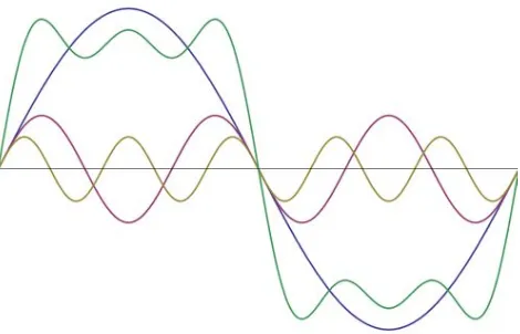
(22) 7. Figure 2.1: The partial construction of a square wave In addition, square waves consist of odd harmonic and don’t have even harmonics. Figure 2.1 shows different forms of wave in the partial construction of a square wave which the wave is in green colour, presented by fundamental sine wave (blue), 3rd harmonic (purple), and 5th harmonic (brown). The amplitude of 3rd harmonic is 1/3 of the fundamental wave and has three times the fundamental frequency with three periods. On the other hand, the 5th harmonic has 1/5 amplitude of the fundamental with five periods. The wavy horizontal line of the green wave will be perfectly square wave if it was added by more different level of harmonics.. 2.3.2. Modified Sine Wave Modified sine wave inverter or as known as quasi-sine wave inverter is an upgrade. of square wave inverter. The waveform of the inverter is in square wave but the waveform has a “stepping” look that more likely in rough approximation shape to a sine wave. Basically, it is the square wave with a dead time; the wave is in positive output, then sits at zero for a moment in off position switch before it goes to negative output and next, sit to zero back before it repeating the operation and emulating the sine wave. The different type of those waveform is shown as in Figure 2.2..
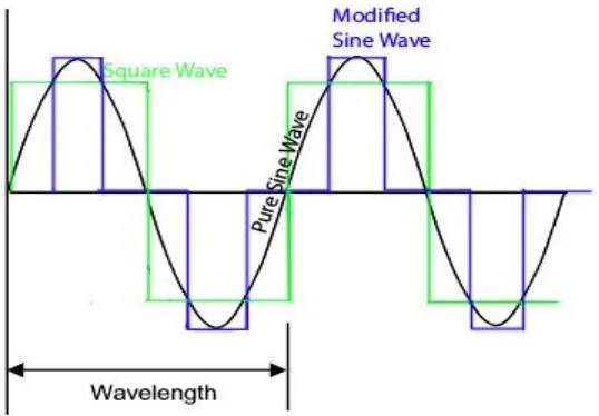
(23) 8. Figure 2.2: Different waveform of square wave, modified sine wave, and pure sine wave inverter. Modified sine wave is very inefficient compared to pure sine wave because it has excessive harmonic frequencies causing high power losses in product such as computers and medical equipment which are not resistant to the distortion of the signal. An inverter with modified sine wave output usually have a harmonic distortion around 40 percent. However, for the household standard basic appliances, the operation of modified sine wave can be outstanding with enough low harmonic that not cause problem although the efficiency or power will be diminish.. 2.3.3. Pure Sine Wave Pure sine wave is the most pre-eminent type of inverter as the waveform has very. less harmonic frequencies and probably the same or better than the power provided from the grid sourced by supplier. The total harmonic distortion of pure sine-wave is just around 3 percent and nearly identical to sine wave. Every most of appliances operates smoothly with the pure sine wave power which has much more advanced efficiency that previous ones. The circuit of the inverter is very complex to design and actualize thus, the difficulty to effectuate the progress of circuits causing this type of inverter is very expensive..
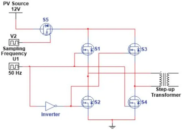
(24) 9. 2.4. Literature Study There are many studies was conducted in order to provide better waveform of. inverter in power supply application. In [7], the study of the single phase 50Hz inverter simulation was conducted in detail about small-voltage AC or DC supply source as demanded to powering small electronic devices. In the study, DC source was provided by solar panel that will soon converted into AC using inverter. The circuit of inverter comprised five power MOSFET switches, four switches connected in H-bridge configuration and one switch for generating sampling frequency. The switches in H-bridge configuration generate sinusoidal AC output by the formation of the positive and negative half cycle produced from four switching devices which operated in 50Hz frequency. In order to generate sampling frequency, switch S5; operates in 5-20 kHz range, was connected in series to one leg of the bridge (S1 and S4) and in series to the other leg (S2 and S3) as shown in Figure 2.3. The output shape of the sinusoidal can be achieve in better shape if the larger sampling frequency is used. In addition, to remove high switching rise and fall time of the large sampling frequency, the low-pass filter was used. The different load applied in the circuit causing the sine pulses gets noisy and distorted. However, these problem can be adjusted by tuning the configurations of the filter and thus refine the high frequency transition and produces sine wave.. Figure 2.3: A single-phase inverter using five power switches.
(25)
Figure

Related documents
Bi-Colour Status L.E.D AC Output Socket On/Off Switch Chassis Ground Fan Cigarette Plug DC Input Lead 12VDC Termianls Display Selection Buttons LCD Screen Remote Input.. AC
communication strategies couples may use to handle stressors they experience during and after breast cancer treatment and psychological distress and relationship
In terms of how teacher knowledge impacts on practical online teaching strategies and course design structures, issues associated with pedagogy, technology and content (as outlined
It is an EEC requirement that a dust extraction facility be provided on power tools, however, due to the nature of the sander, some of the dust produced will be forced into
The simulation results show the integration strategy not only improves the straight track ride quality of the tilting train, but also attenuates the dynamics interaction between
In this research, acetone soluble CA of DS 2.52 has been successfully synthesized from oil palm empty fruit bunches (OPEFB) without the need of the hydrolysis step via a
Thank you for considering participation in a research study entitled The Effect of Federal Laws on the Practice of High School Guidance Counselors in Missouri As They
Serum uric acid level and endothelial dysfunction in patients with nondiabetic chronic kidney disease.. Lower fetuin-A predicts angiographic impaired reperfusion and mortality
