UNIVERSITI TEKNIKAL MALAYSIA MELAKA
DEVELOPMENT OF BUS ALERT SYSTEM USING RF
TRANSMISSION WITH LCD DISPLAY FOR STUDENT
CONVENIENCES
This report is submitted in accordance with the requirement of Universiti Teknikal Malaysia Melaka (UTeM) for the Bachelor of Electronic Engineering Technology
(Telecommunications) With Honours.
by
SHAMSUZZILA BINTI SEBLI B071310242
910514136072
UNIVERSITI TEKNIKAL MALAYSIA MELAKA
BORANG PENGESAHAN STATUS LAPORAN PROJEK SARJANA MUDA
TAJUK: Development of Bus Alert System Using RF Transmission with LCD Display for Student Conveniences
SESI PENGAJIAN: 2016/17 Semester 1
Saya SHAMSUZZILA BINTI SEBLI
mengaku membenarkan Laporan PSM ini disimpan di Perpustakaan Universiti Teknikal Malaysia Melaka (UTeM) dengan syarat-syarat kegunaan seperti berikut: 1. Laporan PSM adalah hak milik Universiti Teknikal Malaysia Melaka dan penulis. 2. Perpustakaan Universiti Teknikal Malaysia Melaka dibenarkan membuat salinan
untuk tujuan pengajian sahaja dengan izin penulis.
3. Perpustakaan dibenarkan membuat salinan laporan PSM ini sebagai bahan pertukaran antara institusi pengajian tinggi.
4. **Sila tandakan ( )
SULIT
TERHAD
TIDAK TERHAD
(Mengandungi maklumat yang berdarjah keselamatan atau kepentingan Malaysia sebagaimana yang termaktub dalam AKTA RAHSIA RASMI 1972)
(Mengandungi maklumat TERHAD yang telah ditentukan oleh organisasi/badan di mana penyelidikan dijalankan)
Disahkan oleh:
** Jika Laporan PSM ini SULIT atau TERHAD, sila lampirkan surat daripada pihak berkuasa/organisasi berkenaan dengan menyatakan sekali sebab dan tempoh laporan PSM ini perlu dikelaskan sebagai SULIT atau TERHAD.
Alamat Tetap:
No. 4591 Desa Indah 3 Bandar Baru Permyjaya, 98000 Miri, Sarawak.
Tarikh: ________________________
Cop Rasmi:
FAKULTI TEKNOLOGI KEJURUTERAAN
Tel : +606 234 6623 | Faks : +606 23406526
Rujukan Kami (Our Ref) : Rujukan Tuan (Your Ref) :
12 JAN 2017 Pustakawan
Perpustakaan UTeM
Universiti Teknikal Malaysia Melaka Hang Tuah Jaya,
76100 Durian Tunggal, Melaka.
Tuan/Puan,
PENGKELASAN LAPORAN PSM SEBAGAI SULIT/TERHAD LAPORAN PROJEK SARJANA MUDA TEKNOLOGI KEJURUTERAAN ELEKTRONIK (TELEKOMUNIKASI DENGAN KEPUJIAN): SHAMSUZZILA BINTI SEBLI
Sukacita dimaklumkan bahawa Laporan PSM yang tersebut di atas bertajuk
“Development Of Bus Alert System Using RF Transmission With LCD Display For Student Conveniences” mohon dikelaskan sebagai *SULIT / TERHAD untuk tempoh LIMA(5) tahun dari tarikh surat ini.
2. Hal ini adalah kerana IANYA MERUPAKAN PROJEK YANG DITAJA OLEH SYARIKAT LUAR DAN HASIL KAJIANNYA ADALAH SULIT.
Sekian dimaklumkan. Terima kasih.
Yang benar,
________________
Tandatangan dan Cop Penyelia
* Potong yang tidak berkenaan
NOTA: BORANG INI HANYA DIISI JIKA DIKLASIFIKASIKAN SEBAGAI SULIT DAN TERHAD. JIKA LAPORAN DIKELASKAN SEBAGAI TIDAK
TERHAD, MAKA BORANG INI TIDAK PERLU DISERTAKAN DALAM
iv
DECLARATION
I hereby, declared this report entitled “Development of Bus Alert System Using RF
Transmission with LCD Display for Student Conveniences” is the results of my own research except as cited in references.
Signature : ……….
Author’s Name : ………
v
APPROVAL
This report is submitted to the Faculty of Engineering Technology of UTeM as a partial fulfillment of the requirements for the degree of Bachelor of Electronic Engineering Technology (Telecommunications) With Honours. The member of the supervisory is as follow:
………
vi
ABSTRAK
vii
ABSTRACT
viii
DEDICATION
Special dedicated to my beloved parents,
Sebli Bin Sanai & Normah Binti Hj. Zainuddin
And my siblings,
Shamsuzzaman Saifur Rahman
Syamimi Syazwani Nursyafiqah Nursyammiza
ix
ACKNOWLEDGEMENT
All praise to the Almighty Allah S.W.T for the breath and strength throughout the entire project until the culmination of this final year project report. I am so grateful and by using this opportunity, I would like to express my sincere gratitude to those who are giving more support and advice through the course of this subject. to my project supervisor, Madam Aziean Binti Mohd Azize and my co-supervisor, Madam Rosziana Binti Hashim for their support and advice through the course of this project. Their guidance from the initial to the final level in developing an understanding of this research thoroughly is really appreciated. Without their advice and assistance, it would be a lot tougher to completion.
Also, I am thankful to my parent Sebli Bin Sanai, Normah Binti Hj. Zainuddin and family members for their love, dream and sacrifice throughout my life. I am really thankful for their sacrifice, patience, and understanding that were inevitable to make this work possible.
x
TABLE OF CONTENT
Abstrak vi
Abstract vii
Dedication viii
Acknowledgement ix
Table of Content x
List of Tables xiii
List of Figures vii
List Abbreviations, Symbols and Nomenclatures xv
CHAPTER 1: INTRODUCTION 1
1.0 Overview 1
1.1 Introduction 1
1.2 Basis of Project 3
1.3 Objectives 3
1.4 Problem statement 4
1.5 Scope 4
CHAPTER 2: LITERATURE REVIEW 6
2.0 Overview 6
2.1 Introduction to Bus Alert System 6
2.2 Related Project Article 7
2.3 Radio Frequency 9
2.3.1 Radio Frequency technology 10
2.4 Hardware Development 11
2.4.1 RF Module 12
2.4.2 Microcontroller 13
xi
2.5 Arduino 14
2.5.1 Arduino Uno 14
2.5.1.1 Power 16
2.6 Liquid Crystal Display (LCD) 17
2.7 Software Development 18
2.7.1 Arduino Software IDE 18
CHAPTER 3: METHODOLOGY 20
3.0 Overview 20
3.1 Flowchart 20
3.1.1 Process of project development 20
3.1.2 Application system 22
3.1.3 Method of using Arduino IDE software. 23
3.2 Project design 25
3.3 Software Utilization 26
3.4 Hardware Development 28
CHAPTER 4: RESULT AND DISCUSSION 31
4.0 Overview 30
4.1 Project Hardware 30
4.1.1 Signal strength 33
4.1.2 Free Space Path Loss (FSPL) 34
4.2 Project test on software 36
4.3 Project test on Breadboard 37
CHAPTER 5: CONCLUSION AND RECOMMENDATION 39
5.1 Conclusion 40
5.2 Recommendation 41
REFERENCE 42
xii
LIST OF TABLES
2.0 Radio Frequency Technology 10
2.1 The radio Frequency (RF) band and their application 11
2.2 Technical specs for Arduino Uno 15
4.0 The condition apply in different distance 32
4.1 Signal strength 33
xiii
LIST OF FIGURES
1.0 Block diagram 3
1.1 System diagram 4
1.2 Distance between Tx-Transmitter and Rx-Receiver 5
2.0 The circuit for blind and bus unit 8
2.1 Block diagram project 8
2.2 RF module 12
2.3 Arduino uno 14
2.4 LCD 16x2display 17
2.5 Serial I2C 1602 LCD module 18
2.6 Example for Arduino Software IDE 19
3.0 Flow chart of project 21
3.1 Flowchart of application system 22
3.2 Flowchart of Arduino IDE software 24
3.3 Arduino IDE software display 25
3.4 Functional block diagram of Bus Alert System 25
3.5 Transmitter Circuit 26
3.6 Receiver circuit 26
3.7 Proteus software 27
3.8 Circuit design in ISIS interface 27
xiv
3.10 Receiver circuit on breadboard 28
3.11 Expected output 29
3.12 Communication check between Tx and Rx. 29
4.0 Output display on LCD 31
4.1. Design of prototype modal for Bus Alert System 31
4.2 Modal prototype of the system 32
4.3 Graph of Signal strength versus distance 34
4.4 Graph of Free Space Path Loss vs Distance 35
4.5 Circuit design using ISIS interface 36
4.6 The circuit after run the program 36
4.7 Disorder output data 37
xv
LIST OF ABBREVIATIONS, SYMBOLS AND
NOMENCLATURE
UTeM - Universiti Teknikal Malaysia Melaka FTK - Faculty of Engineering Technology
SU - Sri Utama
TX - Transmitter
RX - Receiver
RF - Radio Frequency
IR - Infrared
LCD - Liquid Crystal Display LED - Light Emitting Diode Rev3 - Revolution 3
FSPL - Free Space Path Loss
VLF - Very Low Frequency
EHF - Extremely High Frequency
GHz - Gigahertz
1
1.0 Overview
This chapter will briefly discuss on the project background. This chapter also elaborates the problem statement, the objective of this project, and the scope of this project.
1.1 Introduction
Nowadays, the technology is growing rapidly which is in line with the country development. To get as an example, Radio Frequency (RF), it has been widely used
in today’s technology, which suitable use in telecommunications.
The theory states that RF is referring to electromagnetic waves that have a wavelength suited for use in radio communication. Radio waves are classified by their frequencies, which are expressed in kilohertz, megahertz, or gigahertz. Radio frequencies range from very low frequency (VLF), which has a range of 10 to 30 kHz, to extremely high frequency (EHF), which has a range of 30 to 300 GHz. RF technologies is used in many different applications, such as television, radio, cellular phones, radar, and automatic identification systems. Commonly, RF is applied as remote in transfer and receives the signal. Radio Frequency (RF) capable of covering a large area of coverage propagation compare to Infrared(IR). It also can transmit the signal in any direction and not limited to one direction only.
2 To illustrate it in a small electronic device, RF module, this device was used to transmit and receive radio signals between two devices. In an embedded system it is often desirable to communicate with another device wirelessly, and can be accomplished through Radio Frequency (RF) communication or optical communication. RF does not require a line of sight and mostly incorporate with transmitter and receiver. Furthermore, this module is widely used in electronic design owing to the difficulty of designing radio circuitry. Good electronic radio design is notoriously complex because of the sensitivity of radio circuits and the accuracy of components and layouts required achieving operation on a specific frequency.
Besides that, to ensure the reliability of RF communication, it needs carefully monitoring the manufacturing process which is much important and pertinent to the RF performance. RF modules are most often used in medium and low volume products for consumer applications such as garage door openers, wireless alarm systems, industrial remote controls, smart sensor applications, and wireless home automation systems. However, sometimes RF used to replace older infrared communication designs as they have the advantage of not requiring the line-of-sight operation. Several carrier frequencies are commonly used in commercially available RF modules, including those in the industrial, scientific and medical (ISM) radio bands such as 433.92 MHz, 315 MHz, 868 MHz, 915 MHz, and 2400 MHz. These frequencies are used because of national and international regulations governing the use of radio for communication. RF modules may comply with a defined protocol for 3 RF communications such as Zigbee, Bluetooth low energy, or Wi-Fi, or they may implement a Proprietary protocol. (Manna, Pal and Das, 2016).
The project named as “Development of Bus Alert System Using RF
Transmission with LCD Display for Student Conveniences” is help for the student conveniences, in order to reduce the waiting time for the bus at the bus stop. In fact, this will help them to estimate and arrange their time more effectively. Currently, bus alert systems for university only use timetable or schedule system. However the
constraints of timetable system are the University’s student do not alert and warned
3-3 30MHz. The development of the proposed RF remote control consists of designing a transmitter-receiver circuit. A one-directional communication concept is applied in transmitting the signal from transmitter circuit to receiver circuit. A reliable and robust RF bus alert system is expected to be developed.
1.2 Basis of Project
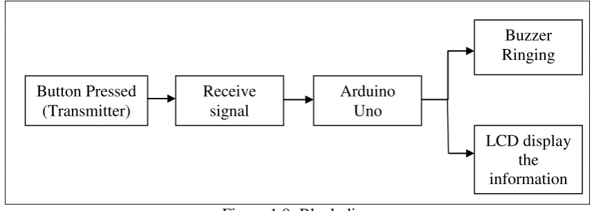
[image:18.595.104.532.367.520.2]Basically, this project will activate the Arduino Uno that already attached along with the receiver module. Then, the Arduino Uno Microcontroller will perform the process to take out the output. At the output part, there will have a buzzer and LCD to perform the system alert in this project. Figure 1.1 illustrated the basic block diagram of the project.
Figure 1.0: Block diagram
1.3 Objectives
The objectives of this project are as stated below;
1. To study the system and design of bus alert system for UTeM Industry campus.
2. To develop bus alert system.
4
1.4 Problem Statements
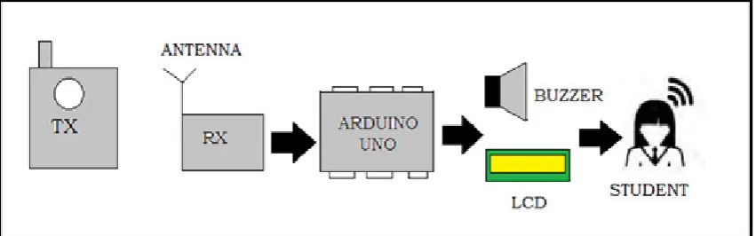
[image:19.595.118.544.287.420.2]The systems use currently at UTeM is only timetable or schedule system. This system was not so effective in giving alert and warned the student about the bus arrival. From observation, some problem occurred regarding this system. For example, the students often waste their time for waiting the bus arrival and also miss taking the bus. Apart from that, there were no specific waiting areas at the hostel, like bus-stop. This leads to the problem that make student unable to get the bus on proper time.
Figure 1.1: System diagram
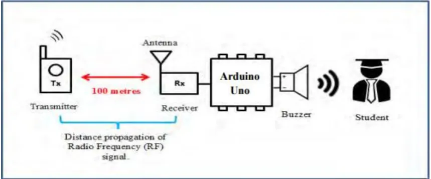
By referring to Figure 1.2, this project provides alarm system to alert and warned the student about bus arrival. The system is equipped with buzzer and the LCD.
1.5 Scope project
5 nature wave help it spread the wave everywhere. So that, the transmitter and receiver not limit to one direction only.
[image:20.595.114.544.253.432.2]Besides, for software development, this system will use Arduino software to program the Arduino Uno microcontroller. In designing the circuit, the suitable software will use is ISIS software. This software will installed together with Proteus software and it can be used for stimulating the circuit created and changing the parameter required.
Figure 1.2: Distance between Tx-Transmitter and Rx-Receiver
6
2.0 Overview
This chapter will discusses a theory and previous project concept. The propose of this chapter is to explain the perspective and method used to complete this project and to discuss how far this project interrelated with study and theory that is existing. Apart from that, this chapter will also show a theory and concept that has been used in solving project problems. Comprehension theoretically is very important as the guide in conducting any study. The result of certain study could not be valued otherwise compared to theory.
2.1 Introduction to Bus Alert System
Nowadays, a development of bus transportation is increasingly stable and develops. However, there are a good and a bad in taking bus transportation. Sometimes, when it comes to taking the public transportation issues, time and patience are of essence. Many of them, experienced time loss because waiting at the bus stop. Hence, a passenger need to know the location of the bus and the time being needed for bus to reach a bus stop.
Means the services provided system is very important. By waiting too long at the bus stop will make the passenger feel reluctant to take a bus. Currently, most bus transportation companies have been providing their timetables on the web freely available for the travelers. According to John et al., (2014) article, they have been provide and implement the idea of giving the notification to their passenger. So that,
7 their passenger will receive extra info like alert the driver when the bus over speeds and also records the bus details, location, date and time. These recordings will help authorities to take action against the culprits. Also the system aids the public from the long waiting hours at the bus stop.
2.2 Related Projects Articles
In this chapter, the research has been done to view what technology has been used to our world due to achieve the same goal regarding the bus alert system. For first example, paper by Chheda et al. (2012), the entitled Real Time Bus Monitoring And Passenger Information System has discuss that, this system has GPS technology, which can help the passenger who is frequently late to work or going to classes. This problem occurs in which condition to deciding whether to wait for the bus or walk or use alternate transport. This system has deployed at the various bus stop around the Mumbai city. The real locations of the buses in Mumbai will be display on the LCD screens on the bus stops.
8
[image:23.595.109.534.71.299.2]Blind Unit Bus unit
Figure 2.0: The circuit for blind and bus unit (Lavanya et al., 2013).
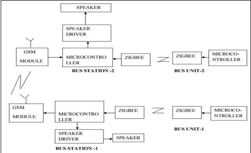
In the next paper, ZIGBEE and GSM based Passenger Bus Alert System by (Sakhare, Bansod and Kedar, 2015) has purpose the system using zigbee and GSM modems. It is a system of automatic Bus announcement for easy transportation.
[image:23.595.113.514.427.672.2]9 Figure 2.2 shows the block diagram for the project.The project uses Zigbee module to detect the bus arrival at the bus station, then the bus will announced at the approaching bus station. The GSM modem then used for the transmitting same information from the present bus station to the next bus station. Thus, the arrival at the present or approaching bus station and the arrival is announced at the next bus station earlier to its actual arrival as well.
2.3 Radio Frequency
In Coleman, 2004 books briefly explained, radio frequency (RF) technology sometimes knows as the exploitation of electromagnetic wave phenomenon that entail in the spectrum between 3Hz and 300Hz. In modern society, this radio frequency technology is most important technologies. It comprises of frequencies applied in communications signals such as radio and television broadcasting and cell-phone and satellite transmissions or radar signal. It also widely used in nowadays technology. As an example, remote control.
Basically, Infrared technology was widely used, such as for home electronic appliances. It easy to use and also low cost. However, infrared technology remote is limited to a specific range which requires a close distance to use. The communication involve in this system is the signal sent only one way and up to 30feet only as viewed in SCV Audio Video, (2013) websites.