HIGH PERFORMANCE 3-DIMENSIONAL WAVEGUIDE CAVITY BANDPASS FILTER OPERATES AT 5.1 GHZ FOR SPECTRUM
ANALYZER
NUR AMIRAH BINTI LATIP
ii
HIGH PERFORMANCE 3-DIMENSIONAL WAVEGUIDE CAVITY BANDPASS FILTER OPERATES AT 5.1 GHZ FOR SPECTRUM ANALYZER
NUR AMIRAH BINTI LATIP
This Report Is Submitted In Partial Fulfilment of Requirements for the Bachelor Degree of Electronic Engineering (Wireless Communication) with Honours
Fakulti Kejuruteraan Elektronik dan Kejuruteraan Komputer Universiti Teknikal Malaysia Melaka
iii
UNIVERSTI TEKNIKAL MALAYSIA MELAKA
FAKULTI KEJURUTERAAN ELEKTRONIK DAN KEJURUTERAAN KOMPUTER
BORANG PENGESAHAN STATUS LAPORAN PROJEK SARJANA MUDA II
Tajuk Projek : …High Performance 3-Dimensional Waveguide Cavity Bandpass
…Filter Operates at 5.1 GHz for Spectrum Analyzer
Sesi Pengajian :
Saya ……….. (HURUF BESAR)
mengaku membenarkan Laporan Projek Sarjana Muda ini disimpan di Perpustakaan dengan syarat-syarat kegunaan seperti berikut:
1. Laporan adalah hakmilik Universiti Teknikal Malaysia Melaka.
2. Perpustakaan dibenarkan membuat salinan untuk tujuan pengajian sahaja.
3. Perpustakaan dibenarkan membuat salinan laporan ini sebagai bahan pertukaran antara institusi pengajian tinggi.
4. Sila tandakan ( √ ) :
SULIT* *(Mengandungi maklumat yang berdarjah keselamatan atau kepentingan Malaysia seperti yang termaktub di
dalam AKTA RAHSIA RASMI 1972)
TERHAD** **(Mengandungi maklumat terhad yang telah ditentukan oleh organisasi/badan di mana penyelidikan
dijalankan)
TIDAK TERHAD
Disahkan oleh:
__ ________________________ ___________________________________
(TANDATANGAN PENULIS) (COP DAN TANDATANGAN
PENYELIA)
iv
“I hereby declare that the work in this project is my own except for summaries and quotations which have been duly acknowledge.”
Signature : ... Author : Nur Amirah binti Latip
v
“I acknowledge that I have read this report and in my opinion this report is sufficient in term of scope and quality for the award of Bachelor of Electronic Engineering
(Wireless Communication) with Honours.”
Signature : ... Supervisor’s Name : PM Dr. Badrul Hisham bin Ahmad
vi
ACKNOWLEDGMENT
Deepest appreciation I express to PM. Dr. Badrul Hisham bin Ahmad, an Associate Professor in Universiti Teknikal Malaysia Melaka and also my Final Year Project’s supervisor, who has sacrificed most of his valuable time in giving the best guidance to me during the two semesters session 2015/2016 to ensure that I can complete this Final Year Project within the duration given by the university. Thank you for all advices, suggestions, help and support for me in completing the Final Year Project as well as writing the Final Year Project’s thesis.
I also want to thanks the lecturers and staffs of Faculty of Electronic and Computer Engineering (FKEKK) especially our Final Year Project’s coordinator, Dr. Kok Swee Leong, for their cooperation, information, suggestions and guidance in the preparation and compilation of the project and the thesis. Special thanks to En Mohd Khairy bin Zahari, a PhD student who is under supervision of PM. Dr. Badrul Hisham bin Ahmad, who willingly to spend his time in helping me throughout the design process and giving advises in improving the results.
vii
ABSTRACT
viii
ABSTRAK
ix
x
TABLE OF CONTENT
TITLE PAGE
ACKNOWLEDGMENT vi
ABSTRACT vii
ABSTRAK viii
TABLE OF CONTENT x
LIST OF TABLE xiv
LIST OF FIGURE xv
LIST OF SYMBOL xviii
CHAPTER 1 – INTRODUCTION
1.1 BACKGROUND OF PROJECT 1
1.2 PROBLEM STATEMENT 3
1.3 OBJECTIVES 3
1.4 SCOPE OF PROJECT 4
xi
1.5.1 Literature Review 5
1.5.2 Determining Design Specification and Parameters 6
1.5.3 Calculation 6
1.5.4 Designing and Simulation of 3-D Waveguide
Cavity Bandpass Filter 6
1.6 THESIS PLAN 7
CHAPTER 2 – LITERATURE REVIEW
2.1 SPECTRUM ANALYZER 8
2.2 MICROWAVE SYSTEM CONCEPT 10
2.3 FILTER RESPONSE 11
2.3.1 Butterworth Response 11
2.3.2 Chebyshev Response 13
2.4 LOWPASS FILTER 14
2.5 HIGHPASS FILTER 15
2.6 BANDPASS FILTER 16
2.7 LOWPASS TO ARBITRARY CUT-OFF
FREQUENCY LOWPASS TRANSFORMATION 17
2.8 LOWPASS TO BANDPASS TRANSFORMATION 18
2.9 IMPEDANCE TRANSFORMATION 19
2.10 BASIC CONCEPT OF S-PARAMETERS 19
xii
2.12 PROPAGATION MODES IN WAVEGUIDE 23
2.12.1 TE Modes 24
2.13 DISCONTINUITIES IN WAVEGUIDE FILTER 25
2.14 DESIGN METHOD OF WAVEGUIDE BANDPASS
CHEBYSHEV FILTER 29
CHAPTER 3 – METHODOLOGY
3.1 WAVEGUIDE CAVITY BANDPASS FILTER
SPECIFICATION 31
3.2 DESIGN PROCEDURES FOR WAVEGUIDE CAVITY
BANDPASS FILTER 32
3.2.1 Chebyshev Lowpass Prototype Network 34
3.2.2 Transformation of Lowpass Prototype into
Waveguide Bandpass Filter 36
3.3 SIMULATION DESIGN OF RECTANGULAR
WAVEGUIDE CAVITY BANDPASS FILTER 41
3.3.1 Rectangular Waveguide without Post 41
3.3.2 Rectangular Waveguide Cavity Filter with Single Post 43
3.3.3 Rectangular Waveguide Cavity Filter with Four Posts 45
xiii
4.1 RECTANGULAR WAVEGUIDE CAVITY BANDPASS
FILTER 48
4.2 ANALYSIS OF RECTANGULAR WAVEGUIDE
CAVITY BANDPASS FILTER 49
CHAPTER 5 – CONCLUSION AND FUTURE WORK
5.1 CONCLUSION 53
5.2 FUTURE WORKS 54
xiv
LIST OF TABLE
NO TITLE PAGE
1.1 Design Specification 4
2.1 Standard Rectangular Waveguide Data[2] 23
3.1 Standard Rectangular Waveguide Data[2] 32
3.2 Design Specification 33
3.3 Element value of Lowpass Prototype 35
3.4 Scaled Element Values of Lowpass Prototype 36
3.5 Element values of waveguide cavity bandpass filter 38
3.6 Comparison between design specification and the
simulated result before optimization 47
4.1 Comparison between design specification and the
xv
LIST OF FIGURE
NO TITLE PAGE
1.1 Rectangular waveguide cavity 2
1.2 Project Methodology Flow Chart 5
2.1 Spectrum Analyzer 9
2.2 The Block Diagram of the Spectrum Analyzer 10
2.3 Maximally flat inverter-coupled lowpass prototype 13 2.4 General Nth degree of Chebyshev lowpass prototype network 14 2.5 Frequency response of 1st order lowpass filter 15
2.6 Frequency response of 1st order highpass filter 16
2.7 Frequency response of bandpass filter 17
2.8 Scattering Parameter 20
2.9 Waveguide geometries 21
2.10 Rectangular Waveguide 22
2.11 End view of TE10 24
2.12 Side View of TE10 24
xvi
2.14 Rectangular waveguide Bandpass Filter 26
2.15 Shunt inductive posts as impedance inverter 26 2.16 Shunt Inductive embedded into a section of waveguide 27 3.1 Position of cylinder posts before optimization 38 3.2 Position of cylinder posts after optimization 40
3.3 Hollow Waveguide 42
3.4 Wave propagation inside the waveguide 42
3.5 Top view of waveguide with wave propagation 42
3.6 Rectangular waveguide embedded with single post
(reference point) 43
3.7 Upper view of rectangular waveguide with single post 43 3.8 S-Parameter graph of the rectangular waveguide with
single post 44
3.9 Rectangular waveguide with two posts 44
3.10 Upper view of rectangular waveguide with two posts 45 3.11 S-Parameter graph of rectangular waveguide with two posts 45
3.12 Rectangular waveguide cavity bandpass filter
before optimization 46
3.13 Upper view of rectangular waveguide cavity
bandpass filter before optimization 46
3.14 S-Parameter graph of rectangular waveguide cavity
bandpass filter before optimization 46
4.1 Rectangular waveguide cavity bandpass filter
xvii
4.2 Upper view of Rectangular waveguide cavity bandpass
filter after optimization 49
4.3 S21 bandpass curve 50
4.4 S11 ripple curve 50
4.5 S-Parameter graph of rectangular waveguide cavity
xviii
LIST OF SYMBOL
𝜔 Angular frequency of passband frequency
𝜔𝑐 Angular frequency of cut-off frequency
𝜆𝑔1 Guide wavelength at lower frequency
𝜆𝑔2 Guide wavelength at upper frequency
𝜆𝑔0 Center guide wavelength
𝑓0 Center frequency
𝑓𝑐 Cut-off frequency
𝑐 Speed of light
𝑎 Waveguide width
𝑙 Waveguide length
𝑏 Height of waveguide
𝐿𝐴 Stopband insertion loss
𝐿𝑅 Passband return loss
𝑁 Degree of Chebyshev / Number of stages
𝑆 Ratio of stopband to passband frequencies
xix
𝛼 Attenuation constant
𝐾 Characteristic impedance of impedance inverter
𝑍 Impedance
𝐵 Susceptance
𝜓 Electrical length
𝐶 Capacitor
𝐿 Inductor
𝑟 Element number
CHAPTER 1
INTRODUCTION
This chapter will explain about the overview project of High Performance 3-D Waveguide Cavity Bandpass Filter. This chapter will cover the summary of the project, objectives, problem statement, project scope and project methodology that will be implemented throughout the project until it successfully done.
1.1 Background of Project
2
[image:21.595.254.418.134.280.2]performance microwave filter since waveguide has a very high Q factor, high power capability and low loss compared to other TEM resonator.
Figure 1.1: Rectangular waveguide cavity
This project will propose a 3D waveguide cavity bandpass filter to be applied in the Spectrum Analyzer that will help in optimizing the performance of the device. The proposed filter will operate at 5.1 GHz frequency with 250 MHz bandwidth. In order to design a high performance filter for the application of Spectrum Analyzer, a very selective bandpass response and a very low insertion loss at the passband must be achieved. Based on the literature study, the waveguide cavity filter will provide both high frequency selectivity and low insertion loss while the bandpass filter will only select the wanted frequencies and reject undesired frequencies. This is the main reason why waveguide cavity bandpass filter is being proposed in this project. Besides, both properties of selective bandpass response and low insertion loss are the key criteria for high Q filter design.
3
1.2 Problem Statement
In this modern and development years, the microwave technologies such as waveguide filters, strip-line filters and microstrip filters are widely being used. Due to the massive usage of the filters, the market demand for a high performance narrow bandpass filters that having low insertion loss and high selectivity.
In the recent trend toward miniaturization, planar technologies such as microstrip and strip-line filters are more preferred than waveguide filters. However, the planar technologies are difficult to meet the high performance specification of bandpass filter application. Among all the filters, the cavity filters are the one that can meet the market demand. Cavity filter is a part of spectrum analyzer, thus, cavity filter requires operation with high performance to result in high accuracy and fine reading and provide high sensitivity. However, the main disadvantage of cavity filter is that it has a large size.
A development and miniaturization of the cavity filter need to be done in order to ensure a longer sustainability of cavity filters in the market. Since it is very difficult to achieve high performance specification in planar technologies, a high performance of 3D waveguide cavity bandpass filter is proposed in order to achieve high selectivity of bandpass and low insertion loss thus will result in high Q factor.
1.3 Objectives
The objectives for the High Performance 3-D Waveguide Cavity Bandpass Filter are:
1) To design and validate the 3D waveguide cavity bandpass filter at 5.1 GHz through simulation using the Ansoft HFSS Software.
4
1.4 Scope of Project
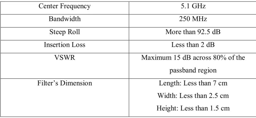
[image:23.595.107.528.263.457.2]In this project, we will include the study background, techniques, calculation, parametric study and the designing procedure of the 3D waveguide cavity bandpass filter. The design and simulation of the 3D waveguide cavity bandpass filter will use the HFSS software. The filter’s design must meet the specification performance of Spectrum Analyzer:
Table 1.1: Design Specification
Center Frequency 5.1 GHz
Bandwidth 250 MHz
Steep Roll More than 92.5 dB
Insertion Loss Less than 2 dB
VSWR Maximum 15 dB across 80% of the
passband region
Filter’s Dimension Length: Less than 7 cm
Width: Less than 2.5 cm Height: Less than 1.5 cm
5
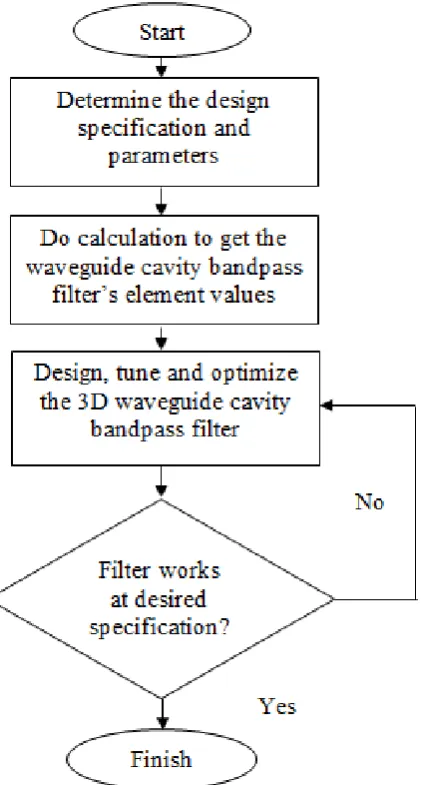
[image:24.595.231.443.121.514.2]1.5 Project Methodology
Figure 1.2: Project methodology flow chart
1.5.1 Literature Review