DESIGN AND MODELING OF MULTIPLE TANK
CONTROL FOR FLUID CIRCULATION SYSTEM USING
FUZZY CONTROLLER
GWEE CHIOU CHIN
UNIVERSITI TEKNIKAL MALAYSIA MELAKA
Design and Modeling of Multiple Tank Control for Fluid
Circulation System Using Fuzzy Controller
Thesis submitted in accordance with the partial requirement of the
Universiti Teknikal Malaysia Melaka for the
Bachelor of Manufacturing Engineering (Robotic & Automation) with Honours
By
UTeM Library (Pind.1/2007)
UNIVERSITI TEKNIKAL MALAYSIA MELAKA
BORANG PENGESAHAN STATUS TESIS*
JUDUL: DESIGN AND MODELING OF MULTIPLE TANK CONTROL FOR FLUID CIRCULATION SYSTEM USING FUZZY CONTROLLER
SESI PENGAJIAN : 2007-2008
Saya GWEE CHIOU CHIN
mengaku membenarkan tesis (PSM/Sarjana/Doktor Falsafah) ini disimpan di Perpustakaan Universiti Teknikal Malaysia Melaka (UTeM) dengan syarat-syarat kegunaan seperti berikut:
1. Tesis adalah hak milik Universiti Teknikal Malaysia Melaka .
2. Perpustakaan Universiti Teknikal Malaysia Melaka dibenarkan membuat salinan untuk tujuan pengajian sahaja.
3. Perpustakaan dibenarkan membuat salinan tesis ini sebagai bahan pertukaran antara institusi pengajian tinggi.
4. **Sila tandakan (XXXX)
SULIT
TERHAD
TIDAK TERHAD
(Mengandungi maklumat yang berdarjah keselamatan atau kepentingan Malaysia yang termaktub di dalam AKTA RAHSIA RASMI 1972)
(Mengandungi maklumat TERHAD yang telah ditentukan oleh organisasi/badan di mana penyelidikan dijalankan)
(TANDATANGAN PENULIS)
Alamat Tetap: Pk 238, Batu 6, Sungai Sendok, 84400 Muar, Johor
Tarikh: 8 October 2007
Disahkan oleh:
(TANDATANGAN PENYELIA)
Cop Rasmi:
Tarikh: _______________________
FAKULTI KEJURUTERAAN PEMBUATAN
Rujukan Kami (Our Ref) : 30 April
2008
Rujukan Tuan (Your Ref):
Pustakawan
Perpustakawan Universiti Teknikal Malaysia Melaka KUTKM, Ayer Keroh
MELAKA.
Saudara,
PENGKELASAN TESIS SEBAGAI SULIT/TERHAD
- TESIS SARJANA MUDA KEJURUTERAAN PEMBUATAN (ROBOTIK & AUTOMASI): GWEE CHIOU CHIN
TAJUK: DESIGN AND MODELING OF MULTIPLE TANK CONTROL FOR FLUID CIRCULATION SYSTEM USING FUZZY CONTROLLER
Sukacita dimaklumkan bahawa tesis yang tersebut di atas bertajuk “Design and Modeling of Multiple Tank Control for Fluid Circulation System Using Fuzzy Controller” mohon dikelaskan sebagai terhad untuk tempoh lima (5) tahun dari tarikh surat ini memandangkan ia mempunyai nilai dan potensi untuk dikomersialkan di masa hadapan.
Sekian dimaklumkan. Terima kasih.
“BERKHIDMAT UNTUK NEGARA KERANA ALLAH”
Yang benar,
WAN HASRULNIZZAM WAN MAHMOOD
Pensyarah,
Fakulti Kejuruteraan Pembuatan
(Penyelia Bersama)
06-2332122
UNIVERSITI TEKNIKAL MALAYSIA MELAKA
Karung Berkunci 1200, Ayer Keroh, 75450 Melaka
iii
DECLARATION
I hereby, declared this thesis entitled “Design and Modeling of Multiple Tank Control for Fluid Circulation System Using Fuzzy controller” is the results of my
own research
except as cited in references.
Signature : ………. Author’s Name : Gwee Chiou Chin
APPROVAL
This PSM submitted to the senate of UTeM and has been as partial fulfillment of the requirements for the degree of Bachelor of Manufacturing Engineering (Robotic and
Automation) with Honours. The members of the supervisory committee are as follow:
……… Main Supervisor
En Muhamad Arfauz Bin Abdul Rahman Faculty of Manufacturing Engineering
v
ABSTRACT
ABSTRAK
vii
DEDICATION
ACKNOWLEDGEMENTS
With the helps and blessing from God, I managed to complete this project successfully. First of all, I would like to thank my parent, for their concern and support, all over the time. Not forgotten my brothers, who had helped me a lot in supporting me physically and morally.
I also want to thank Mr. Muhamad Arfauz Bin Abdul Rahman from Fakulti Kejuruteraan Pembuatan, Universiti Teknikal Malaysia Melaka, for supervising me all along this project, and provide helps, guides, ideas, and suggestions to accomplish this project. All the supports and motivation that been given to me are greatly appreciated.
Also not forgotten, Mr. Salleh and Mr. Asmadi from Bukit Sebukor Water Treatment Plant, for giving a permission to conduct the case study at the Water Treatment Plant.
With a deep sense of gratitude, I would also like to express my sincere thank to my colleague, Jannatunnaim and Noorhayati for the help and supports that been shown by them.
ix
TABLE OF CONTENTS
Declaration………...iii Approval………..………iv Abstract………..………...………....v Abstrak……….vi Dedication………...vii Acknowledgements………...……viii
Table of Contents ………....ix
List of Figures……….xii
List of Tables...xiii
List of Abbreviations, Symbols, Specialized Nomenclature………... .xiv
1. INTRODUCTION ………..1
1.1Project Introduction ………...1
1.2Problem Statement ...………..………...2
1.3Objective...………..3
1.4Scopes ……….3
2. LITERATURE REVIEW ……….5
2.1 Introduction ………....5
2.2 Control system ………6
2.2.1 Open Loop and Closed Loop System ………..………….9
2.2.2 Fuzzy Logic ………..……..12
2.3 Level Controllers ………..13
2.4 Flow Controllers ………...14
2.5 Water Level and Flow Control Devices ………16
2.5.1 Level Sensor ………16
2.5.2 Flow Meter ………..17
2.5.3 Water Valve ………18
2.6 Fuzzy Logic Controller ……….21
2.6.1 Structure of a Fuzzy Controller ………..24
2.6.2 Fuzzy Logic Toolbox ……….24
2.7 Fuzzy Controller versus PID Controller ………...25
2.8 Water Filter ………...28
2.9 Concluding Remarks ………... 29
3. METHODOLOGY ……….………...31
3.1 Introduction ………..31
3.2 Project Design ……..………...31
3.3 System Design .……….33
3.4 Project Methodology .………...35
3.4.1 Case Study …………..………35
3.4.2 Research ………..35
3.4.3 Interview ……….35
3.4.4 Observation ……….36
3.5 Project Tools ……….36
3.5.1 Books ………..36
3.5.2 Papers ………..36
3.5.3 Internet ………37
3.5.4 Software ………..37
3.6 Project Planning ………38
3.6.1 Project Planning for PSM 1 ………38
3.6.2 Project Planning for PSM 2 ………41
4. CASE STUDY ………..43
xi
5. DESIGN SIMULATION ...………...50
5.1 Introduction ...50
5.2 System Development ...50
5.3 Development of SIMULINK Block Diagram ...51
6. RESULTS & DISCUSSION……...……….56
6.1 Introduction ...56
6.2 Results ...56
6.3 Concluding Remarks ... 60
7. CONCLUSION & SUGGESTIONS ...61
7.1 Introduction ...61
7.2 Summary ...61
7.3 Conclusion ...63
7.4 Suggestions & Recommendations ...74
LIST OF FIGURES
2.1 Simplified Description of a Control System 6
2.2 Elevator Response 8
2.3 Open Loop System 9
2.4 Closed Loop System 10
2.5 Direct Control 22
2.6 Feed Forward Control 23
2.7 Fuzzy parameter adaptive control. 23 2.8 Blocks of a Fuzzy Controller 24 2.9 Fuzzy Logic Based Control System 27 3.1 Flow of the Project Design 32 3.2 Flow of the System Design 34 4.1 Bukit Sebukor Water Treatment Plant 42
4.2 PLC Monitoring 46
4.3 Filter Control Panel 46
4.4 Lamella Filtration Tank 47 4.5 Lamella Filtration Tank structure (Architecture Drawing) 48 4.6 Lamella Filtration Tank Structure (Simplified Drawing) 49 5.1 Simulink Library Browser 51
5.2 Empty Simulink Window 52
5.3 Block Diagram for the new system. 52 5.4 Water Tank Block Parameters Window 53 5.5 Penstock Block Parameter Window 54
5.6 Rule Editor Window 54
xiii
LIST OF TABLES
3.1 Gantt chart for PSM 1 40
3.2 Gantt chart for PSM 2 42
LIST OF ABBREVIATIONS, SYMBOLS, SPECIALIZED
NOMENCLATURE
AWWA - American Water Works Association CPVC - Chlorinated PVC
DP - Differential pressure GUIs - Graphical user interfaces I/O - Input/Output
P - Proportional
PD - Proportional plus derivative / Positive displacement PI - Proportional plus integral
PID - Proportional, integral, and derivative PSM - Projek Sarjana Muda
PTFE - Polytetrafluoroethylene PV - Photovoltaic
PVC - Polymers, polyvinyl chloride UV - Ultraviolet
1
CHAPTER 1
INTRODUCTION
1.1
Project Introduction
Level and flow control system is a technique used to control the level and flow of circulation system for variety of purpose. It can be used to control either fluid or even air for pneumatic or hydraulic system. There are few types of process that use the level and flow control system, such as water treatment centre, water dam, tank level control, and liquid flow control and circulation system.
In this project, the Lamella Filtration system of Bukit Sebukor Water Treatment Plant is studied. The objective of this project was to upgrade the mechanical water level control system of the Lamella Filtration system to an automatic system. The automation of the Lamella Filtration system can help reducing the burden of the technicians on shift and prevent human error on manual operation.
Previous study on fluid level control using SIMULINK was carried out by previous student. [15] In his study, the design and modeling tank control for fluid circulation system using SIMULINK had been designed. Unfortunately, the system is not suitable to be applied at the current Lamella Filtration system.
1.2
Problem Statement
Nowadays, most of the fluid level and flow system are still applying the mechanical control to control the circulation system. [15] Floating limit switch, diaphragm valve and solenoid which connected by simple wiring are the examples of main control device that normally used in mechanical control.
The current Lamella Filtration system of Bukit Sebukor Water Treatment Plant uses a mechanical control system. Technicians are required on shift to monitor the control system twenty four hours a day.
The main criterion that needs to be controlled in level and flow of a fluid circulation is the rate of the main supply and the distribution system. Complete system with suitable control need to be considered to achieve this.
The mechanical control system’s device is subjected to tear and wear itself. For the example, floating limit switch has a cycle rate which will turn to be malfunction after the cycle rate. At the same time it is also subjected to tear and wear caused by the movement of the switch.
3
1.3
Objective
The main objective of this project is to control and model multiple tank fluid level control system using Fuzzy Controller. In order to achieve the main objective, following are some additional objectives to be completed:
a) To evaluate the current fluid level control.
b) To design and propose an automatic fluid level control system that can replace the current mechanical system.
c) To control and simulate the designed Lamella Filtration tank fluid control system.
1.4
Scopes
The scopes of this project are:
a) Data Collection
b) Design and Simulation
5
CHAPTER 2
LITERATURE REVIEW
2.1
Introduction
The literature review that have been done to gain more information on the project that been carried out is describes in this chapter. Firstly, the basic explanation on the control system is discussed. After that, it is followed by the discussion of the lamella filtration tank fluid level control and the devices that needed in controlling this system. Finally is the control application using the Fuzzy Logic Toolbox with the aid of Matlab is discussed.
2.2
Control System
According to Wikipedia [1], a control system is a device or set of devices to manage, command, direct or regulate the behavior of other devices or systems.
Control systems are an integral part of modem society. Nowadays, there are many applications using control system. Lots of example can be found in daily life, such as washing machine, air-conditioner, and microwave.
There are also control systems that exits in the naturally. For the example, pancreas which regulates human blood sugar level and photosynthesis by plants.
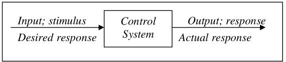
[image:22.612.159.444.450.512.2]A control system consists of subsystem and processes assembled for the purpose of controlling the outputs of the processes [2]. The air-conditioner that produces more cool air as the result of the room temperature increase is an example. Air conditioner use thermostat to measure the temperature of the room. Thermostat is as a subsystem that will be the input for the system. The control system will provide an appropriate output or response for the given input or stimulus. Figure 2.1 [2] shows the process.
Figure 2.1: Simplified Description of a Control System
Input; stimulus Desired response
Output; response Actual response Control
7
Control system where built for four primary reasons:
a) Power amplification.
A control system can produce the needed power amplification, or power gain. For example, a radar antenna, positioned by the low-power rotation knob at the input, requires a large amount of low-power for its output rotation. By using the control system, the power that needed can be produce by amplifying the power needed.
b) Remote control.
Robot design by control system principles can compensate for human disabilities. Control systems are also useful for remote at dangerous location. For example, a remote controlled robot arm can be used to pick up material in a radioactive environment.
c) Convenience of input form.
Control system can be used to provide convenience by changing the form of the input. A temperature control system as an example. The position on the thermostat is the input, while the output is the heat. Thus, a convenient position input yields a desired thermal output.
d) Compensation for disturbance.
position, or if noises enter internally, the system must be able to detect the disturbance and correct the antenna’s position. The system’s input is obviously will not change to make correction. Consequently, the system itself must measure the amount that the disturbance has repositioned the antenna and then return the antenna to the position commanded by the input.
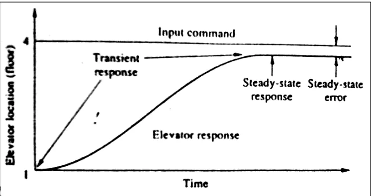
[image:24.612.126.499.331.529.2]A control system provides n output or response for a given input or stimulus. The input represents a desired response, and the output is the actual response. For example, when the fourth-floor button of an elevator is pushed on the ground floor, the elevator rises to the fourth-floor button of a speed and floor-leveling accuracy designed for passenger comforts is shown in Figure 2.2 [2].