ULTRASONIC RANGE METER
RAHIAH BINTI ABDUL HAMID
This report is submitted in partial fulfilment of the requirements for the award of Bachelor of Electronic Engineering (Industrial Electronics) With Honours
Faculty of Electronic an Computer Engineering Universiti Teknikal Malaysia Melaka
*CATATAN : Jika laporan ini SULIT atau TERHAD, sila lampirkan surat daripada pihak berkuasalorganisasi berkenaan dengan menyatakan sekali tempoh laporan ini perlu dikelaskan sebagai SULIT atau TERHAD.
i
@
UNIVERSITI TEKNIKAL MALAYSIA MELAKAFAKULTI KEJURUTERAAN ELEKTRONIK DAN KEJURUTERAAN KOMPUTER
'h,
-
BORANG PENGESAHAN STATUS LAPORAN
PROJEK SARJANA MUDA I1
T a j u k Projek: Ultrasonic Range Meter Sesi Pengajian: 2007108
Saya RAHIAH BINTI ABDUL HAMlD mengaku membenarkan laporan Sarjana Muda ini disimpan di Perpustakaan dengan syarat-syarat kegunaan seperti berikut:
I. Laporan adalah hakmilik Universiti Teknikal Malaysia Melaka. 2. Perpustakaan dibenarkan membuat salinan untuk tujuan pengajian sahaja.
3. Perpustakaan dibenarkan membuat salinan laporan ini sebagai bahan pertukaran antara institusi pengajian tinggi. 4. Sila tandakan ( 4 ) :
0
SULIT* (Mengandungi maklumat yang berdarjah keselamatan atau kepentingan Malaysia seperti yang termaktub di dalam AKTA RAHSIA RASM11972)0
TERHAD* (Mengandungi maklumat terhad yang telah ditentukan oleh organisasilbadan di mana penyelidikan dijalankan)0
TIDAK TERHAD(TANDATANGAN PENULIS)
Alamat Tetap: hnsyorah
No.56, Jalan Sekolah, Fakul Kej E k W i k C n Kej Kmputer (FKEKQ, Universiti Teknikal Malays~a Melaka (UToM),
Kg. Melayu Majidi, Karung Berkuna 1206, Hang Tuah Jaya
81 100 Johor Bahru. Ayer Keroh, 75450 Melaka.
Johor.
"I hereby declare that this thesis entitled, Ultrasonic Range Meter is a result of my own research idea except for works that have been cited clearly in the references."
Signature :
W
Name : RAHIAH BINTI ABDUL HAMID
"I, hereby declare that this I have read this report an in my opinion this report is sufficient in terms of scope and quality for the award of Bachelor of Electronic Engineering (Industrial Electronic) with honours."
Signature Name
Special dedication to my loving mum Pn Juminah bt Sarbini, my dad En Abdul Hamid bin Hj Sidek, my brother, my kind hearted supervisor En Ahrnad Sadhiqin bin
ACKNOWLEDGEMENT
I have completed my thesis for PSM 1 which is a partial fulfilment of requirements for the degree of Bachelor in Electronic Engineering (Industrial Electronics).
On this opportunity, I would like to express my gratitude to the Faculty of Electronic and Computer Engineering, Universiti Teknikal Malaysia Melaka (UTem) and sincere gratitude to my supervisor, En. Ahmad Sadhiqin bin Mohd Isira, for his assistance and guidance towards the progress of this thesis project. En Ahrnad Sadhiqin has been patiently monitoring my progress and guided me in the right direction and offering encouragement. Obviously the progress I have now will be inconsistent without his assistance.
I am grateful to my family especially my dearest mom and dad, Puan Juminah bt Sarbini and En Abdul Hamid b Hj Sidek and my sibling for their unfailing encouragement and financial support for me to complete this thesis.
ABSTRACT
ABSTRAK
CONTENT
CHAP. TITLE PAGES TITLE OF PROJECT
REPORT STATUS VERIFICATION FORM STUDENT'S DECLARATION SUPERVISOR'S DECLARATION DEDICATION ACKNOWLEDGMENT ABSTRACT ABSTRAK CONTENTS LIST OF TABLE LIST OF FIGURE ABREVIATION
LIST OF APPENDICES INTRODUCTION
1.1 Introduction of Project 1.2 Objectives Project 1.3 Problem statement 1.4 Scope of work
LITERATURE REVIEW
2.1 Ultrasonic
2.2 Type of Ultrasonic Transducer 2.2.1 Piezoelectric
2.2.2 Magnetostrictive 5 The differences Ultrasonic Transducer 6 between others transducer
The factors effects when measuring the distance 6 The propagation speed of the sound 6
The Ultrasonic Range Meter 9
2.6.1 The Block Diagram 9
2.6.2 Circuit of Ultrasonic Range Meter 10 The operations circuit of Ultrasonic Range Meter 11
2.7.1 Transmitter circuit 11
2.7.2 Receiver circuit 12
2.7.2.1 Signal Amplification circuit 12
2.7.2.2 Detection circuit 13
2.7.2.3 Signal Detector 13
2.7.2.4 Signal Holding Circuit 14 2.7.2.5 Temperature revision voltage 15
generating circuit
2.7.1.6 Resonator 16
2.7.1.7 Power supply 17
2.7.1.8 Seven segment LED 17
The components 18
2.8.1 Ultrasonic sensor 18
2.8.2 PIC 16F873 18
2.8.3 Low noise operational amplifiers (LM833N) 19 2.8.4 Low power operational amplifiers (LM358) 19
2.8.5 NAND gates (401 1 B) 19
2.8.6 Inverters (4069UB) 20
2.8.7 3 terminal voltage regulator for +5 V (7805) 20 2.8.8 3 terminal voltage regulator for +9 V (78L09) 20 2.8.9 Transmitter drive transistor (2SC 18 15) 2 1 2.8.10 Shottky barrier diode ( 1 SS 106 ) 2 1
2.8.1 1 Resonator 2 1
2.8.12 Variable resistor for display proofreading 22
2.8.14 Ceramic Capacitor
2.8.15 Multilayer ceramic capacitor 2.8.16 Electrolytic capacitor
2.8.17 Printed circuit board 2.8.1 8 Jumper Wire
2.9 PIC microcontroller
2.9.1 Development Languages 2.10 The PIC 16F783
2.1 1 The other type of Ultrasonic Range Meter 2.1 1.1 Transmitter circuit
2.1 1.2 Receiver circuit
2.1 1.3 The comparison between Ultrasonic Range Meter with PIC and without PIC.
PROJECT METHODOLOGY
3.1 The flow chart of methodology project
3.2 Explanation about the flow chart of methodology 3.2.1 Literature review for the Ultrasonic
Range Meter
3.2.2 Design the circuit and simulate 3.3 Construct circuit and hardware
3.3.1 Etching process 3.3.2 PCB drilling process
3.3.3 Component mounting process 3.4 Software programming
3.5 Circuits testing
RESULT
4.1 The simulation of Receiver circuit 4.2 The result from simulation
4.2.1 The result for Oscilloscope 1 4.2.2 The result for Oscilloscope 2 4.2.3 The result for Oscilloscope 3 4.2.4 The result for Oscilloscope 4 4.3 The result from testing circuit
4.3.1 The power supply circuit result 4.3.2 The receiver circuit result
4.4 The result of final Ultrasonic Range Meter
DISCUSSION AND CONCLUSION
5.1 Discussion 5.2 Conclusion
LIST OF TABLE
TITLE
The differences of transducer The speed of sound
The time for measuring the distance The Features of PIC 16F873
The comparison of Ultrasonic Range Meter circuit The power supply circuit result
The receiver circuit result
LIST OF FIGURE
TITLE PAGES
Ultrasonic Range Meter
The process of Ultrasonic Range Meter block diagram The circuit of Ultrasonic Range Meter
The transmitter block
The signal amplification circuit The detection circuit
The signal detector circuit The signal holding circuit
The temperature revision voltage generating circuit The resonator circuit
The power supply circuit LED seven segment display
The Ultrasonic Range Meter without using PIC The flow chart of methodology project
Result for LM 833N at pin 7 Result for LM 833N at pin 1
ABREVIATION
PIC - Programmable Integrated Circuit PCB
-
Printed Circuit BoardLIST OF APPENDICES
NO TITLE
A Source code of Ultrasonic Range Meter B LM7905 and LM7909 datasheet
C PIC 16F876A Datasheet
CHAPTER I
INTRODUCTION
1.1 Introduction of Project
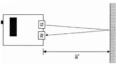
The Ultrasonic Range Meter is designed to measure the distance of any object in between 0.25m to 8m using standard 40 kHz transducer. It is useful for the robotic project. The measured distance is displayed on the seven segment connected to the Programmable Integrated Circuit(P1C). The time taken by the propagation of the ultrasonic signal sent to the object or place where it will take the effect of temperature change as well in order to determine the distance. The propagation speed of the sound changes with the temperature. All of those controls are done by the software of PIC. The type of PIC used for this project is 16F873.
[image:18.516.150.349.611.722.2]1.2 Objectives
The objectives of this project are:
i) To design the Ultrasonic Range Meter using hardware and software (PIC programming).
ii) To design and create and seven segment displayed distance measurement device.
iii) To study and familiarize with PIC programming.
iv) Study and familiarize with the transducer, signal amplification circuit, detection circuit, signal detector and other signal conditioners.
1.3 Problem statement
1.4 Scope of project
Four steps taken to develop this device:
1. Literature review for the Ultrasonic Range Meter
Information gathering from books, internet and discussion with the supervisor.
Analysis about the project.
Study about the PIC programming and the operations of circuit.
2. Software design
Design the PIC program by using assembly language. Test run and troubleshoot the program
3. The circuit and hardware design and construction.
The circuit is designed by using Multisim for the simulation of circuit. The circuit is constructed and measured to know the differences between the simulation results.
The hardware is built and some adjustment are made for troubleshooting purpose.
4. Test run and troubleshoot
The hardware and the software are integrated.
CHAPTER I1
LITERATURE REVIEW
2.1 Ultrasonic
Ultrasonic is the sound that refers to anything above the frequencies of audible sound, and nominally includes anything over 20,000 Hz.
Ultrasonic can be used to locate objects by means similar to the principle by which radar works. High-frequency acoustic waves reflect from objects, even comparatively small ones, because of the short wavelength. The distance to an object can be determined by measuring the delay between the transmission of an ultrasound pulse and the return of the echo. This is the well-known facts by which bats navigate in darkness. It is also believed to be used underwater by cetaceans such as dolphins and whales. Ultrasonic can be used in sonar systems to determine the depth of the water in a location, to find schools of fish, to locate submarines, and to detect the presence of SCUBA divers.
2.2 Type of Ultrasonic Transducer
There are two types of ultrasonic transducer:
2.2.1 Piezoelectric
Crystals which acquire a charge when compressed, twisted or distorted are said to be piezoelectric. This provides a convenient transducer effect between electrical and mechanical oscillations. Quartz demonstrates this property and is extremely stable. Quartz crystals are used for watch crystals and for precise frequency reference crystals for radio transmitters. Rochelle salt produces a comparatively large voltage upon compression and was used in early crystal microphones. Barium titanate, lead zirconate, and lead titanate are ceramic materials which exhibit piezoelectricity and are used in ultrasonic transducers as well as microphones. If an electrical oscillation is applied to such ceramic wafers, they will respond with mechanical vibrations which provide the ultrasonic sound source. The standard piezoelectric material for medical imaging processes has been lead zirconate titanate (PZT). Piezoelectric ceramic materials have found use in producing motions on the order of nanometers in the control of scanning tunneling microscopes.
2.2.2 Magnetostrictive
2.3 The differences Ultrasonic Transducer between others transducer Table 2.1 : The differences of transducers
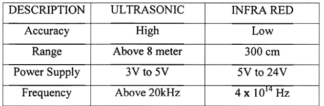
2.4 The factors effects when measuring the distance DESCRIPTION
Accuracy Range Power Supply
Frequency
The factors effects when measuring the distance are: 1. Temperature
2. The propagation speed of the sound 3. Time
4. Distance
2.5 The propagation speed of the sound ULTRASONIC
High Above 8 meter
3V to 5V Above 20kHz
The speed of sound describes how much distance such a wave travels in a given amount of time. In Earth atmosphere the speed varies with atmospheric conditions; the most important factor is the temperature. The formula for the speed of sound in air is:
INFRA RED Low 300 cm 5V to 24V 4 1014 HZ
Csound in air = 33 1.5 t 0.6 Tc ,where T, is Celsius temperature
Calculation;
Table 2.2: The speeds of sound
This range meter calculates a distance by dividing the propagation time which was measured by the capture feature. The calculation for determine the time when measure a distance is showed as below:
Temperature of air "C
-10 -5 0 5 10 20 25 3 0 40
Assume Tc = 30 "C, and the distance to measure is 1 meter. The speeds of sound