UNIVERSITI TEKNIKAL MALAYSIA MELAKA
STUDY ON DRILLING AERO COMPOSITE
MATERIAL
Thesis submitted in accordance with the requirements of the Universiti Teknikal Malaysia Melaka for the Degree of
Bachelor of Manufacturing Engineering (Manufacturing Process) with Honors
By
Mohd Hairi B Hamad Tajudin
UTeM Library (Pind.1/2007)
UNIVERSITI TEKNIKAL MALAYSIA MELAKA
BORANG PENGESAHAN STATUS LAPORAN PSM
JUDUL:
STUDY ON DRILLING AERO COMPOSITE MATERIAL
SESI PENGAJIAN: Semester 2 2007/2008
Saya MOHD HAIRI B HAMAD TAJUDIN
mengaku membenarkan laporan PSM / tesis (Sarjana/Doktor Falsafah) ini disimpan di Perpustakaan Universiti Teknikal Malaysia Melaka (UTeM) dengan syarat-syarat kegunaan seperti berikut:
1. Laporan PSM / tesis adalah hak milik Universiti Teknikal Malaysia Melaka dan
penulis.
2. Perpustakaan Universiti Teknikal Malaysia Melaka dibenarkan membuat salinan
untuk tujuan pengajian sahaja dengan izin penulis.
3. Perpustakaan dibenarkan membuat salinan laporan PSM / tesis ini sebagai bahan
pertukaran antara institusi pengajian tinggi.
4. *Sila tandakan (√)
SULIT
TERHAD
TIDAK TERHAD
(Mengandungi maklumat yang berdarjah keselamatan atau kepentingan Malaysia yang termaktub di dalam AKTA RAHSIA RASMI 1972)
(Mengandungi maklumat TERHAD yang telah ditentukan oleh organisasi/badan di mana penyelidikan dijalankan)
FAKULTI KEJURUTERAAN PEMBUATAN
Rujukan Kami (Our Ref) : 09 Februari 2012
Rujukan Tuan (Your Ref):
Pustakawan
Perpustakaan Universiti Teknikal Malaysia Melaka (UTeM) Taman Tasik Utama, Hang Tuah Jaya,
Ayer Keroh, 75450, Melaka
Saudara,
PENGKELASAN LAPORAN PSM SEBAGAI SULIT/TERHAD
- LAPORAN PSM SARJANA MUDA KEJURUTERAAN PEMBUATAN (PROCESS): MOHD HAIRI BIN HAMAD TAJUDIN
TAJUK: STUDY ON DRILLING AERO COMPOSITE MATERIAL
Sukacita dimaklumkan bahawa tesis yang tersebut di atas bertajuk “Study on Drilling Aero Composite Material” mohon dikelaskan sebagai terhad untuk tempoh lima (5) tahun dari tarikh surat ini memandangkan ia mempunyai nilai dan potensi untuk dikomersialkan di masa hadapan.
Sekian dimaklumkan. Terima kasih.
“BERKHIDMAT UNTUK NEGARA KERANA ALLAH”
Yang benar,
………..
Y.M. RAJA IZAMSHAH B RAJA ABDULLAH
Pensyarah,
Fakulti Kejuruteraan Pembuatan
UNIVERSITI TEKNIKAL MALAYSIA MELAKA
Karung Berkunci 1200, Ayer Keroh, 75450 Melaka
STUDY ON DRILLING AERO COMPOSITE MATERIAL
iii
DECLARATION
I hereby declare that this report entitled “STUDY ON DRILLING AERO COMPOSITE MATERIAL” is the result of my own research except as cited in the
references.
Signature :
Author’s Name : MOHD HAIRI B HAMAD TAJUDIN
APPROVAL
This report is submitted to the Faculty of Manufacturing Engineering of UTeM as a partial fulfillment of the requirements for the degree of Bachelor of Manufacturing
Engineering (Process). The members of the supervisory committee are as follow:
………. Y. M RAJA IZAMSHAH B RAJA ABDULLAH
v
ABSTRACT
ABSTRAK
vii
DEDICATION
ACKNOWLEDGEMENTS
ix
TABLE OF CONTENT
Declaration………...iii Approval………..iv Abstract ………v Abstrak……….vi Dedication………vii Adknowledgements………viii
Table of Contents……….ix
List of Figure………..xiii
List of Table……….xv
List of Abbreviations ………...xvi
CHAPTER 1 INTRODUCTION 1.1 Problem Statement……….………1
1.2 Scope of Project……….………2
1.3 Objective……….2
CHAPTER 2 LITERATURE REVIEW 2.1 Introduction………..….….3
2.2 CNC Milling Machine………..…..4
2.3 Drilling……….….….6
2.3.1 Drilling Process……….…….….6
2.3.2 Drilling Types……….….……6
2.3.3 Aero Composite Drilling……….…7
2.3.4 Cutting Condition……….…...8
2.3.5 Common Problem in Drilling Composite……….….10
2.4 Cutting Tool………..….10
2.4.1 Saw Drill……….…...11
2.4.2 Core Drill……….……..11
2.5 Drill Bit Material……….……..13
2.5.1 High Speed Steel……….………...14
2.5.2 Carbides or Coated Carbide……….……..16
2.6 Chip Formation Analysis……….…….18
2.6.1 Chip Produce……….……….19
2.7 Material……….….20
2.7.1 Advance Composite……….…...21
2.7.2 Material Type and Properties……….…….22
2.7.3 Matrix Material……….…..23
2.7.4 Reinforcing Fibers……….………….24
2.7.5 Advance Composite………25
2.7.6 Term in Composite………..26
2.8 Backup Plate………...29
2.9 Strengthness of Drilled Hole………..30
2.10 Surface Roughness of Drilled Hole………..30
2.11 Design of Experiment……….…..32
CHAPTER 3 METHODOLOGY 3.1 Introduction……….33
3.2 Selection of Material………....35
3.2.1 Basic Air Craft Structure………..36
3.2.2 Axes Rotation………37
3.2.3 Specific Structure of composite Material……….38
3.3 Machining Parameter Setting………...39
xi
3.61 Haas CNC Milling Machine………....45
3.6.2 Special Features………..…46
3.7 Experiment Analysis Method………47
3.7.1 Universal Tensile Strength Machine(UTM)………...47
3.7.2 Optical Microscope……….48
3.7.3 Coordinate Measuring Machine………..49
3.7.4 Scanning Electron Microscope………50
CHAPTER 4 RESULT 4.1 Surface roughness (Ra)……….……....51
4.1.1 Saw Drill bit……….……….……51
4.1.2 Core Drill bit ……….…...52
4.1.3 Step Drill bit ………54
4.1.4 Drilling Without Using Back Up Plate……….………55
4.1.5 Drilling Using Back Up Plate………...56
4.2 Effect on Tensile Strength……….………. 58
4.2.1 Saw Drill bit……….……….58
4.2.2 Step Drill bit………..59
4.2.3 Core Drill bit……….………….61
4.2.4 Drilling Without Using Back Up Plate……….……….62
4.2.5 Drilling Using Back Up Plate……….……...63
4.3 Effect on Structure Using SEM………64
CHAPTER 5 DISCUSSION 5.1 Relationships between the surface roughness and parameter setting…….…..65
5.2 Relationships between the tensile strength and parameter setting...………….66
5.3 Surface defects on the material after drilling operation………67
5.2.1 Crack………..67
CHAPTER 6 CONCLUSSION AND RECOMMENDATION
6.1 Conclusions………..68
6.1 Recommendation……….……….69
REFERENCES……….………70
xiii
LIST OF FIGURE
Figure 2.0: CNC Milling Machine ………..…….. 4
Figure 2.1: Feed rate application ………..…. 9
Figure 2.2: Circular plate model for saw drill analysis………..11
Figure 2.3: Circular plate model for core drill analysis...…...11
Figure 2.4: Circular plate model for step drill analysis………..….…12
Figure 2.5: Flow chart for chip formation analysis………..…….. 18
Figure 2.6: Drilling with backup plate……….……... 29
Figure 2.7: Drilling without backup plate………..………. 30
Figure 3.0: Flow Chart………..…….. 34
Figure 3.1: Basic Air Craft Structure……….…. 35
Figure 3.2: A320 carbon fiber panel……… 35
Figure 3.3: Structure of the flaps wing……….……38
Figure 3.4: Saw drill bit……….…….……...40
Figure 3.5: Core drill bit………...40
Figure 3.6: Step drill bit………...………..…...41
Figure 3.7: CNC milling machine……….….….….…….45
Figure 3.8: Experiment setup……….. ……….………..…….46
Figure 3.9: Universal Testing Machine (UTM)……….….……….47
Figure 3.10: Optical Microscope………..………48
Figure 3.11: Scanning Electron Microscope (SEM)……….…50
Figure 4.1: Surface Roughness Vs Parameter Setting, X (Feed Rate & Spindle Speed) for Saw Drill……….52
Figure 4.2: Surface Roughness Vs Parameter Setting, X (Feed Rate & Spindle Speed) for Core Drill………53
Figure 4.3: Surface Roughness Vs Parameter Setting, X (Feed Rate & Spindle Speed) for Step Drill ………...55
Figure 4.5: Surface Roughness Vs Parameter Setting, X (Feed Rate & Spindle Speed) for panel that drilled by using back up plate……….………..57
Figure 4.6: Maximum Force Vs Parameter Setting, X (Feed Rate & Spindle Speed) for Saw Drill……….……..58 Figure 4.7: Maximum Force Vs Parameter Setting, X (Feed Rate & Spindle Speed) for Step Drill………..…60 Figure 4.8: Maximum Force Vs Parameter Setting, X (Feed Rate & Spindle Speed) for Core Drill……….….61 Figure 4.9: Maximum Force Vs Parameter Setting, X (Feed Rate & Spindle Speed) for aero composite panel that drilled without using back up plate…………62
Figure 4.10: Maximum Force Vs Parameter Setting, X (Feed Rate & Spindle Speed) for aero composite panel that drilled by using back up plate………63
xv
LIST OF TABLE
Table 2.0: Parameter setting of drill test………..9
Table 2.1: Types and General Characteristic of Composite Material………..24
Table 3.0: Control factor with back up plate………43
Table 3.1: Control factor without backup plate………43
Table 4.1: Surface Roughness data for Saw Drill……….51
Table 4.3: Surface Roughness data for Core Drill………52
Table 4.2: Surface Roughness data for Step Drill……….54
Table 4.4: Maximum Force data for Saw Drill……….…58
Table 4.5: Maximum Force data for Step Drill……….………59
LIST OF ABBREVIATIONS, SYMBOLS, SPECIALIZED
NOMENCLATURE
ANOVA - Analysis of Variance
CMC - Ceramic Material Composite CNC - Computer Numerical Control CFRP - Carbon Fiber Reinforced Plastic CMM - Coordinate Measuring Machine
CTRM - Composite Technology Research Malaysia DOE - Design of Experiment
EDM - Electrical Discharge Machining FRP - Fiber Reinforced Plastic
FMEA - Failure Mode and Effect Analysis HIP - Hot Isostatic Pressing
HSS - High Speed Steel
MMC - Material Matrix Composite PMC - Polymer Material Composite SEM - Scanning Electron Microscope TiAlN - Titanium Aluminum Nitride TiN - Titanium Nitride
UTM - Universal Testing Machine
V - Vanadium
1
CHAPTER 1
INTRODUCTION
In recent years, polymer composites have gained considerable attention in the aircraft industries due to their light weight and high strength. Even though most of the polymer composite structures are molded into near-net shapes, machining of the components is always necessary to attain the required dimensional tolerance, surface roughness, and complex geometry.
Aircraft manufacturers spend millions of dollars reworking blown fastener holes, especially in portable tool drilling situations. Oval, tapered, rifled, and oversize holes are costly rework issues currently commonplace in the industry. Drilling is one of the major machining operations which are currently carried out on fiber-reinforced composite materials. There are typical problems encountered when drilling fiber-reinforced composites.
1.1 Problem statement
In the aircraft industry, drilling associated delamination accounts for 60% of all part rejections during final assembly of an aircraft. In most cases of drilling aero composite material, the majority of the residual stresses is cause by plastic deformation of the workpiece by the tool. According to Astrom (1997) there are several common problems associated with drilling carbon fiber, with delamination and excessive tool wear usually report as the biggest concern. The thrust forces increases as drill wear increase. The effect of processing variables also contributes to drilling damage. The hole machining defects have significantly reduced the strength and fatigue life of carbon/epoxy laminates. This study is focusing to minimize those problems.
1.2 Objective
The purpose of this study is to aim the objective below:
i. To analyze the performance of different type of drill (saw drill, core drill and step drill) in drilling of aero composite material.
ii. To study the effects of drilling parameter (cutting speed and feed) on the hole performance.
iii. To study the effects of backup plate for minimizing the hole defects.
1.3 Scope of project
i. Drilling the aero composite using three type of the drilling bit. a) saw drill
3
CHAPTER 2
LITERATURE REVIEW
2.1 Introduction
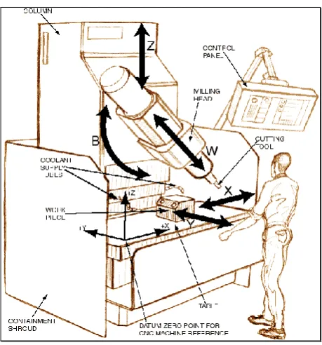
2.2 CNC Milling Machine
Computer Numerical Control (CNC) Milling is the most common form of CNC. CNC Milling is classified according to the number of axes that they possess. Axes are labeled as x and y for horizontal movement, and z for vertical movement, as shown in this view of a manual milling table. A standard manual light-duty mill is typically assumed to have four axes:
1. Table x. 2. Table y. 3. Table z.
[image:22.595.191.421.476.722.2]5 Frame
i. Base ii. Column iii. Over arm
Produce the basic structure of the machine. It includes a base to provide stability to the machine, column to provide the height and over arm to support the machine spindle.
Spindle
The device which transmits power from the machine motor to the cutter and provides rotary motion for the cutter. The spindle may be placed horizontally or vertically.
Knee
The knee of the milling machine supports the saddle and the table. The knee is connected to the column and can move up and down on asset of way.
Saddle
The saddle is the machine element between the knee and the table. The saddle moves in and out along ways on the knee.
Table
2.3 Drilling
Many manufactured parts and products require machine operations that put holes in them. These holes may be part of the functional design of the product or are for product assembly with fasteners such as screws, bolts, rivets, shafts, tabs, and tapered pins.
Holes may be produced using a number of manufacturing processes. They may be made by punching, making cores in casting operations, flame cutting, ultrasonic machining, drilling, fly cutting, hole sawing, boring, and electrical discharge machining (EDM). This chapter will discuss those hole- producing operations which are performed on drilling by using the CNC Milling Machine.
2.3.1 Drilling process
Drilling is a machining operation used to create a round hole in a work part. Drilling is usually performed with a rotating cylindrical tool that has two cutting edges on its working end. The tool call is drill or drill bit. The rotating drill feeds into the stationary work part to form a hole whose diameter is equal to the drill diameter. Drilling is customarily performed on a drill press, although other machine tools also perform this operation.
2.3.2 Drill types