AUTO VOLTMETER MEASUREMENT TOOL SYSTEM
Muhammad Luqmannul Hakim Bin Ahmad Buhairi
“I hereby declare that I have read through this report entitle “Auto-Voltmeter Measurement Tool System” and found that it has comply the partial fulfillment for awarding the degree of Bachelor of Electrical Engineering (Mechatronic)”
Signature :
Supervisor’s : Mr. Zaihasraf Bin Zakaria
ii
AUTO-VOLTMETER MEASUREMENT TOOL SYSTEM
MUHAMMAD LUQMANNUL HAKIM B. AHMAD BUHAIRI
A report is submitted in partial of fulfillment of the requirements for the degree of
Bachelor in Electrical Engineering (Mechatronic)
Faculty of Electrical Engineering
UNIVERSITI TEKNIKAL MALAYSIA MELAKA
iii
I declared that this report entitle “Auto-Voltmeter Measurement Tool System” is the result of my own research except as cited in the references. The report has not been accept for any degree and is not concurrently submitted in candidature of other degree.
Signature :
Name : Muhammad Luqmannul Hakim Bin Ahmad Buhairi
iv
Dedicated to my beloved mother, father, my siblings And all my friends,
v
ACKNOWLEDGEMENT
Thanks to Almighty, after many months of hard works in completing FYP1 (Final Year Project 1), at last this report has been completed. Finally, the day has comes for me to expressing my gratitude to anyone who has make contribution in completing the FYP 1 project. I would like to extend my highest appreciation and gratitude to:
First and foremost, Mr Zaihasraf Bin Zakaria, as my FYP supervisor, who has inspired and guided me in achievement of this Project Report.
He inspired me greatly to work in this project. His willingness to motivate me contributed tremendously to my project. I also would like to thank him for willingness to showing me some example that related to the topic of my project.
vi
ABSTRACT
In industry, maintenance routine is compulsory to be done for machines or power station in any factory or office. This is to ensure that the machines or power supply does not have faulty error during any production time or business. If it happen, it will affect the whole company production and cause to money loss and waste of production time. Thus, these will become a problem that need to be solve. As a scenario, during industrial training program that is held for degree students, there is a company conducting a preventive maintenance for uninterruptible power supply (UPS). A voltmeter, is a common item that is use for voltage measurement by maintenance technician. During maintenance routine of UPS, technician need to check the condition of battery backup for UPS system to ensure it does not have faulty error when main power is down. There are several chances of having danger of electrical shock due to a problem while measuring voltage of the backup battery. It is because of narrow space in the battery rack, which is fixed enough for only to place the battery. Thus, there is not enough space for technician to reach the positive and
negative battery terminals. Therefore, a project called ’Auto-Voltmeter Measurement
vii
ABSTRAK
viii
TABLE OF CONTENTS
CHAPTER TITLE PAGE
ACKNOWLEDGEMENT v
ABSTRACT vi
ABSTRAK vii
TABLE OF CONTENTS viii – xi
LIST OF TABLES xii
LIST OF FIGURES xiii – xv
LIST OF SYMBOLS AND ABBREVIATIONS xvi
LIST OF APPENDICES xvii
1 INTRODUCTION 1
2 LITERITURE REVIEW 6
2.1 Introduction 6
2.2 Voltmeter as Voltage Measurement Tool 7
2.2.1 Introduction 7
2.2.2 Digital Voltmeter 8 – 10
2.3 Uninterruptible Power Supply (UPS) Battery 10 – 13
ix
CHAPTER TITLE PAGE
2.4 Product Comparison 14
2.4.1 Comparison between Analog Voltmeter and 15 – 16 Digital Voltmeter
2.4.2 Comparison between the SLA Seal 16 – 17
Lead-Acid Battery and Motorcycle
Battery
2.4.3 Microcontroller 17 – 18
2.4.4 Microprocessor 19
2.4.5 Comparison between Microcontroller and 19 – 20
Microprocessor
2.5 Hardware Specification 21
2.5.1 PIC16F877A 21 – 23
2.5.2 DC Motor 24
2.5.3 H-Bridge (L298) 25 – 27
2.5.4 Liquid Crystal Display (16x2 Dot Matrix) 27 – 28
2.5.5 Digital Voltmeter (Voltage Measurer) 28 – 29
2.6 Software Specification 29
2.6.1 MikroC 6.2 29 – 30
2.6.2 Proteus 7.0 Professional 31 – 32
x
CHAPTER TITLE PAGE
2.6.4 SolidWorks 2007 33 – 34
3 METHODOLOGY 35
3.1 Introduction 35
3.2 Project Construction Flow Chart 36 – 37
3.3 Hardware Development 37
3.3.1 Main Circuit 38
3.3.2 Controller Circuit 39 – 40
3.4 Software Development 40 – 41
4 RESULT 42
4.1 Introduction 42
4.2 Result 42
4.2.1 Software Phase 43
4.2.1.1 Simulation of Motor Motion 43 – 47
4.2.1.2 Simulation of Voltage Reading 48 – 50
4.2.2 Hardware Phase 50 – 51
xi
CHAPTER TITLE PAGE
5 CONCLUSION 54
5.1 Introduction 54
5.2 Discussion of the Project 54 – 55
5.3 Suggestion for Future Works 55
5.4 Conclusion 56
REFERENCES 57
xii
LIST OF TABLES
TABLE TITLE PAGE
2.9 Comparison between Analog Voltmeter and 15
Digital Voltmeter
2.10 Comparison between SLA Sealed Lead Acid Battery and 16
Motorcycle Battery
2.13 Difference between Microcontroller and Microprocessor 20
2.16 PIC16F877A Device Features 22
xiii
LIST OF FIGURES
FIGURE TITLE PAGE
1.1 System Block Diagram 4
2.1 Analog Voltmeter and Digital Voltmeter 7
2.2 Digital Voltmeter’s Block Scheme 9
Dual Slope’s A/D Converter
2.3 Dual Slope’s A/D Converter Timing Diagrams 10
2.4 Simple Version of Static UPS 11
2.5 Uninterruptible Power Supply 11
2.6 Diagram of how UPS operating when it backup 11
the main system
2.7 Formula of calculation to determine the battery capacity 12
2.8 Batteries Installation Layout 13
2.11 Microcontroller 17
2.12 Microprocessor 19
2.14 PIC16F877A Microcontroller 21
2.15 Pin Diagram of PIC16F877A 40-Pin PDIP 22
2.17 PIC16F877A Block Diagram 23
xiv
FIGURE TITLE PAGE
2.19 Dual Full-Bridge Driver L298 25
2.20 Block Diagram of L298 H-Bridge 26
2.21 Pin Connections for L298 H-Bridge 26
2.23 Liquid Crystal Display (16x2 Dot Matrix) 27
2.24 Digital Voltmeter 28
2.25 MikroC 6.2 29
2.26 MikroC Windows Interface 30
2.27 Proteus 7.0 Professional 31
2.28 Proteus Professional Windows Interface 31
2.29 WinPic800 32
2.30 WinPic800 Windows Interface 32
2.31 SolidWorks 2007 33
2.32 SolidWorks Windows Interface 34
3.1 Project Design Flow Diagram 36
3.2 Schematic of Main Circuit 38
3.3 Schematic of Controller Circuit 39
3.4 Software Development Diagram 40
4.1 Motor Motion Circuit 44
xv
FIGURE TITLE PAGE
4.3 Power is supplied to the motor circuit and green 46
led is illuminated
4.4 Green led turns OFF and instead red led is ON and 46
forward motor is in motion
4.5 Forward motor stopped and down lid motor is activated 47
with the yellow led
4.6 Down lid motor is stopped and up lid motor is in motion 47 with the illumination of blue led
4.7 Side motor is in motion for changing lane on the 48
battery rack
4.8 Voltage Reading Circuit 49
xvi
LIST OF SYMBOLS AND ABBREVIATIONS
LCD Liquid Crystal Display
PIC Programmable Integrated Circuit
I/O Input/Output
RAM Random-access Memory
ROM Read-only Memory
OTP ROM One-Time Programmable Memory
KHz kiloHertz
DC Direct-current
TTL Transistor-transistor logic
IDE Integrated Development Environment
xvii
LIST OF APPENDICES
APPENDIX TITLE PAGE
A Gantt chart for FYP1
B Coding
CHAPTER 1
INTRODUCTION
1.1 Background
A voltmeter is an instrument used for measuring the electrical potential difference between two points in an electric circuit. There are two types of voltmeter existed, which are the analog voltmeter and digital voltmeter. Analog voltmeter move a pointer across a scale in proportion to the voltage of the circuit while the digital voltmeter gives a numerical display of voltage by use of an analog to digital converter.
Voltmeters are made in a wide range of styles. General purpose of analog voltmeter may have an accuracy of a few percent of full scale and are used with voltages from a fraction of a volt to several thousand volts. While digital voltmeter can be made with high accuracy, typically better than 1 percent. Meters using amplifiers can measure tiny voltages of microvolts or less.
2
chances of having danger of electrical shock due to a problem while measuring voltage of the backup battery. It is because of narrow space in battery rack, which is fixed enough for only to place the battery. Thus, there is not enough space for technician to reach the positive and negative battery terminals.
Nowadays, with the vast technology application available, it is possible to create a microcontroller based to control a system which it is programmed to take a battery backup voltage measurement automatically with reducing the danger of the technician may have.
The microcontroller based automatic voltmeter measurement system consists of two elements to be considered:
i. Software development
ii. Hardware development
The achievement of the project can be stated that the system will have the ability to make a backup battery voltage measurement automatically with reducing the dangers that technician in maintenance routine may have.
1.2 Problem Statement
During maintenance routine, technician always expose with such dangers like having an electrical shock, electrical spark which can cause paralyzed and sometimes causing some power explosion which is seriously dangerous and can causes death.
3
Therefore, with this project we can reduce the danger that the technician may have in the future. Furthermore, the routine of the maintenance can be done with such efficiency and good performance.
1.3 Objective of Project
There are two objectives of this project:
1. To develop an automatic voltmeter system that can take readings of voltage
automatically from the backup battery.
2. To help technician during the maintenance routine.
From the first objective, an automated controller for voltage measurer is created with the application of robotic innovation by using microcontroller based PIC to control the system automatically through the whole battery rack for voltage measurement without the intrusion of technician to take the readings. The system running by itself after power is on.
4
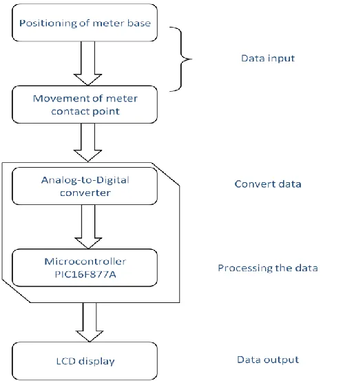
[image:22.612.191.440.130.406.2]1.4 Scope of Project
Figure 1.1: System Block Diagram
Auto-voltmeter system consists of three parts, which are the data input, data processing and data output. In the data input part, it has two functioning devices which are the meter base and the contact point mover. As the data processing part, it consist the microcontroller and finally the data output part, LCD display plays the role.
5
Lastly, overall scope of the project is to design an automatic voltmeter system controlled by PIC microcontroller and to make an implementation of mechanical design combining with voltmeter to create a semi-robot product.
1.5 Outline of Progress Report
CHAPTER 2
LITERATURE REVIEW