Abstract—A novel current control strategy is proposed for
voltage source converters connected to weak grids using conventional current vector control with additional current error based voltage angle and magnitude compensations. For connecting to very weak AC network, the combination of vector control and grid synchronization with conventional Phase-Locked-Loop (PLL) is proved to be unstable; whereas the proposed current error based compensations can significantly improve system stability. In this way, the proposed control can still benefit from the presence of closed-loop current control without the need for control switching during large AC voltage variations. Comprehensive frequency domain model is established to analyze stability performance. Comprehensive time domain simulations are further carried out to validate its effectiveness and robustness by demonstrating its current control performance during a three-phase fault, multiple-converter situation and various grid strength conditions.
Index Terms— voltage source converter, weak grid, current
control, stability, fault current.
I. INTRODUCTION
Wind energy is nowadays one of the main renewable energy resources. Most of the newly developed or planned wind farms are placed far from conventional centralized power plants [1][2]. Meanwhile, the capacities of the wind farms are growing. The average size in Europe had been more than doubled during the period between 2010 and 2015 [2]. As a result, the grid connection points of the large wind farms become weaker. As is defined, a grid connection is classified to be ‘weak’ when its Short Circuit Ratio (SCR), which is defined by the prospected 3-phase fault current over the nominal current, is less than 3 and “very weak” when SCR is less than 2 [3]. Since the fault level is the ratio of fault current against local nominal current and the line impedance, which is generally proportional to transmission distance, longer transmission distances can give rise to smaller values of SCR. As the fault current is largely determined by the grid side configuration, the growing local power (current) capacity can decrease the SCR and the consequent grid strength as well. Theoretically, the SCR can be very low as long as the local source capacity is sufficiently large. A consequent problem of weak grid is that the Voltage Source Converter (VSC)
This work is supported in part by the EPSRC, project reference numbers EP/G037728/1S and EP/L014343/1.K.
interfaced (fully-rated) power generations tend to be unstable with conventional vector control and similar situation may arise when VSC based High Voltage Direct Current (HVDC)
is connected to a relatively weak network
[4][5][7][10][11][12][32].
To deal with the instability caused by the weak grid, various studies have been carried out. One immediate thought is to reinforce the grid strength by investing in grid infrastructures which can be costly. Other efforts have been mainly focused on improving the converter control of wind turbines [5-7].
For the prevalent implementation, fully rated VSCs are widely used in wind turbine grid integrations. Closed current loop with vector control is a classical way to control the VSCs [8] both in steady state or during transients [9]. However, when it is applied to a converter connected to a weak grid it can become unstable when the power reaches a certain level [10-12]. The interactions between converter control and grid dynamics (including VSC reactor, transmission line impedance, harmonic filter, etc.) is considered to be the main causes for this issue [13].
Power flow and dynamics are the two major aspects considered for such instability [5, 13-20]. To deliver bulk power in a weak grid, there has to be sufficient voltage at the connecting point to enable the active power flow, hence the reactive compensation [5, 19, 20]. The other aspect is the dynamics. It is reported that the inclusion of conventional PLL as a synchronizing method in a closed-loop current control may introduce instability when the power reaches a certain level at weak grid, which can undermine the coordinate transformation based vector control [18, 21]. Although it is true that the tuning of a conventional PLL, i.e. by reducing the bandwidth, can improve the damping, it still cannot guarantee the stability for rated power delivery along with a satisfactory transient performance from weak grids. The system level behavior needs to be investigated in addition to the PLL itself considering the interaction between converter control and the grid dynamics.
A variety of methods have been explored to address the dynamic issues of VSC control when connected to a weak grid [5-7, 10-12, 22, 24, 25]. The methods can be generally categorized into two types: virtual synchronous generator control based [11, 12, 22, 24, 25] and vector control based [10].
The Virtual Synchronous Generator (VSG) based controls are also known as [22], “synchronverter” [25] or power
Current Error Based Compensations for VSC
Current Control in Weak Grids for Wind Farm
Applications
Electrical and Electronic Engineering Copyright. The copy of record is available at IEEE Xplore Digital Library. synchronization control [11], etc., which mimic the behavior
and control scheme of synchronous generators when they are integrated into the grid. This type of control is based on the fact that a properly controlled synchronous machine can well generate bulk power from weak grid point, which has been studied for decades. Similar to synchronous generator control, closed-loop power control is performed by directly controlling the modulation voltage angle and magnitude of the converter voltage. In this case, the employment of Phased Locked Loop, which is widely used in vector control for angle detection, can be by-passed from the closed-loop control during steady state operation [11]. These methods enable VSC to output full power from a very weak grid point and work well in steady state operation. However, the absence of current loop in such method can potentially give rise to extra current variations during large perturbations. An extreme case is that during an AC fault, virtual synchronous generator and the power synchronization control themselves will not be able to limit the fault current and it has to be switched to a current-loop based control mode with a back-up PLL [11]. Such non-linear mode switching scheme increases the complexity of VSC control and one consequent problem is that it would be difficult to determine where the switching point should be set to avoid undesirable mode switches, especially when unpredictable perturbations, voltage fluctuations or fault, occur when VSCs are operating close to their rated power/current. As another attempt of the virtual synchronous machine concept, the control strategy of Virtual Synchronous Machine (VISMA) presented in Ref [23] employs a special designed outer loop in addition to a hysteresis-based inner current loop in abc reference frame. However, the presented method was not tested to demonstrate satisfactory performance under both full-power steady-state and fault-ride-through conditions in weak grids.
The other type of VSC control strategy in weak grid involves closed-loop current control, which has been less explored. They can be further divided into two categories - gain tuning based and orientation modification based. The gain scheduling power control technique is proposed with additional cross-coupling control based on the conventional vector control with fairly good performance in weak grid [10]. However, it involves complicated non-linear tuning curves for a number of gain combinations. As the tuning curve combinations have to be predefined, this process makes it difficult and inconvenient to obtain a satisfactory performance for variable system conditions. The efforts on PLL gain tuning optimization can improve system performance to some extent [15] though, it is still difficult to handle the situation when the grid is very weak. For the orientation modification based methods, the reference orientation modification is introduced to enhance the synchronization [19][26][32]. Control based on virtual PCC bus has also been proposed to enhance the stability in very weak grid [19, 26], but it requires information of grid impedance before configuring the control; hence the control settings can be sensitive to the possible changes of grid conditions. A modified PLL is introduced to compensate the frequency based on the current error inside the conventional PLL [32]; however, it might still have high frequency oscillation when delivering full power at extremely weak grid and it is not clear if the control delay has been considered in
model analysis and validation, which may give rise to more ideal results than possible.
In this paper, a current error based angle and magnitude compensation strategy is proposed based on classical VSC vector control, which improves system stability of classical vector control and enables the converter to deliver full power to a very weak grid. Control mode switching is no longer needed during both steady state and transient operation. Further, the proposed strategy also benefits from easy implementation, simple modification based on prevalent implementation in industry and good robustness against grid strength variation.
The rest of this paper is organized as follows. The principles of the proposed control strategy are presented in Section II, and Section III describes the system modeling and control analysis. Case studies concerning both steady state and voltage transients are carried out in Section IV and finally conclusion is drawn in Section V.
II. PRINCIPLES OF VSC CONTROL AND PROPOSED CURRENT ERROR BASED VOLTAGE ANGLE AND MAGNITUDE
COMPENSATION
In this section, the principle of the proposed current control method is introduced.
[image:2.612.314.561.337.704.2]A. The stability problem of vector control in weak grid
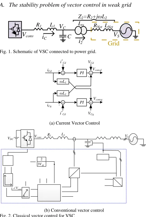
Fig. 1. Schematic of VSC connected to power grid.
(a) Current Vector Control
(b) Conventional vector control Fig. 2. Classical vector control for VSC
The simplified schematic diagram of a 3-phase VSC connected to a power network is shown in Fig. 1, where R1
VS
VC
Vconv
i2
iC
Grid Z2=R2+jωL2
C
R1 L1 Ltx RNet LNet
PI
PI ωL1
ωL1
+
+ +
+
-VCd
VCq
-i*
Cd
iCd
iCq
i* Cd
Vconvd
Vconvq
L1
R1
VDC Vconv VS
PLL
IC V C
iCq
abc dq
VCd
VCq
PWM P*
y
x
|Vconv| r
Vconvd*
Vconvq *
Current Vector control
iCd
abc dq θ
VCq
VCd Cd V 3
2
iCd *
iCq*
L2
R2
conv V
Voltage Sampling
C
u
rr
en
t
S
am
p
li
n
g
and L1 represent the resistance and inductance of the VSC
reactor, respectively. C is the harmonic filter capacitance; Ltx
is the equivalent inductance of the converter transformer, and
RNet and LNet are the equivalent resistance and inductance of
the network, respectively. Vc and Vconv refer to the respective
capacitor voltage and the converter output voltage. R2 and L2
represent the equivalent grid side resistance and inductance seen on the converter side of the transformer. As this paper mainly focuses on AC side integration, the impact of DC side dynamics of the VSC is assumed to be negligible.
For the VSC system shown in Fig. 1, there is
𝑉𝐶𝑑𝑞= 𝑉𝑐𝑜𝑛𝑣𝑑𝑞− 𝐿1
𝑑𝑖𝐶𝑑𝑞
𝑑𝑡 − 𝑗𝜔𝐿1𝑖𝐶𝑑𝑞− 𝑖𝐶𝑑𝑞𝑅1 (1)
where iCdq = iCd + jiCq , VCdq = VCd + jVCq and Vconvdq = Vconvd + jVconvq are the vectors of converter current, capacitor voltage
and converter voltage in synchronous d-q reference frame respectively; 𝜔 is the angular velocity.
The conventional vector current control is shown in Fig. 2 [27] where d-q based control scheme is used as the d-axis is conventionally aligned to the AC voltage vector VC at the
point of connection and ω is the system angular frequency. Considering a modulation cycle of Ts, (1) can also be
expressed as
𝑑𝑖𝐶𝑑𝑞 =
𝑑𝑡
𝐿1𝑉𝑐𝑜𝑛𝑣𝑑𝑞− 𝑑𝑡 𝐿1𝑉𝐶𝑑𝑞0−
𝑑𝑡
𝐿1𝑗𝜔𝐿1𝑖𝐶𝑑𝑞0−𝑖𝐶𝑑𝑞0𝑅1 𝑑𝑡 𝐿1 (2)
where VCdq0 the operational voltage of the integration point; iCdq0 the operational current of the VSC.
In conventional vector control, taking advantage of the linearized relationship against 𝑑𝑖𝐶𝑑𝑞 in (2),
V
convdq is used asthe current regulation output to control the current
i
Cdq .Considering (2) converter current error is set as the input and converter voltage as the output as Vconvdq is directly
controllable for a VSC.
As is shown in Fig. 3, a ramp power test is carried out based on the schematic of Fig. 1 and conventional control strategy of Figs. 2(a) and (b). The converter power rating at 6 MW, SCR
at 1 p.u. for illustration of a very adverse case (excluding transformer impedance), L1, Rl, C, and transformer inductance
at 0.2 p.u., 0.001 p.u. and 0.1 p.u. respectively. The base power is selected as the rated power. Considering over-current allowed of an industrial converter is limited, 20% for instance, for the economical concern, the maximum power deliverable at steady state is considered to be up to 1 p.u. in this paper. The VSC switching frequency is typically considered as 2.5 kHz for IGBT in medium-high power applications.
Considering (1), the plant of VSC current (connecting to ideal stiff grid) in d-q reference frame can be ideally considered as a first-order process 1/Lls, where R assumed to
be negligible for the most adverse case and simplicity as well. For convention current loop setting with PI regulator in Fig. 2 (a), the proportional and integral gains can be conventionally set at Kp = 141πL1 and Ki = 10000π2L1 respectively, which
corresponds to a 50 Hz bandwidth current loop with damping coefficients of 0.707 connection with 2.5 kHz switching frequency [28]. The sampling process of current and voltage is typically considered as twice of the switching frequency since the modulation input of a practical SVPWM module used (for
the prevalent digital signal processor of TMS320F28XX series produced by Texas Instrument) can be effectively updated twice per switching cycle [34]. For linearization concern, the PWM control is therefore modeled as a first order process of a time constant of half switching cycle as the high frequency switching harmonics can be reasonably ignored for the dynamic analysis.
As shown, during steady state operation, the conventional vector control is able to regulate the current/power when the generated power is low and the angle error between the actual and PLL measured AC voltage angles of Vc converges to 0,
which means the PLL is able to track the grid angle. However, when the power rises to approximately 65%, the angle error grows larger and starts oscillation, which inevitably undermines the coordinate transformation based vector control leading to power oscillations. It can be seen that the oscillation frequency is around 40 Hz for this case.
Fig. 3. Power ramp test with conventional vector control (from top to bottom: active power, actual voltage angle of Vc; PLL detected voltage angle of Vc, error between the actual and measured angle of Vc)
It can be seen from Fig. 3 that, significant angular error are induced when the output power has reached more than approximately 0.65 per unit, which gives rise to the failure of power delivery or vice versa. Obviously, for a stabilized system, the angular tracking error should have been eliminated. An angular error compensation control strategy is therefore proposed to eliminate the angular error and more importantly, improve the damping of the overall system.
B. Principles of current error based compensation
Setting voltage vector aligned on d-axis and assuming that the VSC resistance R1 is negligible, the steady-state active
power can also be expressed as [29]
𝑃 =3
2𝑉𝐶𝑑𝑖𝐶𝑑=
𝑉𝑐𝑜𝑛𝑣𝑉𝐶𝑑
Electrical and Electronic Engineering Copyright. The copy of record is available at IEEE Xplore Digital Library. where P refers to the active power generated; δ the power
angle between the converter output (with voltage magnitude of
Vconv) and network integration point (with voltage magnitude
of Vc); Vcd and icd the instant d-axis converter voltage and
current. Assuming the variation of Vcd is negligible at steady
state, it can be linearized from (3) based on a certain operational point as
2𝑑𝑃
3𝑉𝐶𝑑= 𝑑𝑖𝐶𝑑 =
2𝑉𝑐𝑜𝑛𝑣0
3𝜔𝐿1 𝑑(𝑠𝑖𝑛𝛿) +
2𝑠𝑖𝑛𝛿0
3𝜔𝐿1 𝑑𝑉𝑐𝑜𝑛𝑣 (4)
Rearranging (4) yields
𝑑𝑖𝐶𝑑≈
2𝑉𝑐𝑜𝑛𝑣0
3𝜔𝐿1 𝑑𝛿 +
2𝑠𝑖𝑛𝛿0
3𝜔𝐿1 𝑑𝑉𝑐𝑜𝑛𝑣 (5)
where Vconv0 and δ0 are the static operational point of Vconv and δ respectively. From (5), it can be found that the incremental current 𝛥𝑖𝐶𝑑 can be approximated in linear relationship to 𝛥𝛿.
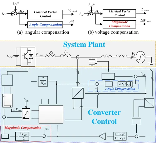
(a) angular compensation (b) voltage compensation
(c) VSC vector control scheme with compensations
Fig. 4. VSC with current vector control and proposed current error based compensations
Similar to Fig. 2 and (2), therefore an active current-error based compensation can be designed with PI regulator based
on (4). Giving |2𝑉𝑐𝑜𝑛𝑣0
3𝜔𝑠𝐿1| ≫ |
2𝑠𝑖𝑛𝛿0
3𝜔𝑠𝐿1| during steady state, dδ has
the major impact on active current change and hence is used as the output of angle compensation, which is similar to the control design in Fig. 2 that is based on (2). Thus, an additional active current control is proposed to add the regulation with the angle compensation as another output in parallel with the conventional vector control, which is shown in Fig. 4 (a). Considering the linearized relationship between
ΔiCd and dδ in (4) and (5), a closed-loop angle compensation is
proposed in Figs. 4(a)(c) with the converter current of d-axis
iCd as the feedback. In this way, angle tracking can be
improved by adding extra damping and meanwhile the main current loop continues providing fast dynamic response during large perturbations and transients. The comprehensive implementation of the proposed active current control is demonstrated by Fig. 4(c). The scaling coefficient of “ωL1/|𝑉𝐶|” in the “Angle Compensation”, as shown in Fig. 4,
is used to cancel the relevance of the corresponding PI tuning to the values of angular velocity, converter inductance and capacitor voltage considering (4) so the successful tunings can apply to a variety of ratings.
Similar to (3)-(5), for reactive current, there is [29]
𝑄 = −3
2𝑉𝐶𝑑𝑖𝐶𝑞=
𝑉𝑐𝑜𝑛𝑣(𝑉𝑐𝑜𝑛𝑣−𝑉𝐶𝑑)
𝜔𝐿1 𝑐𝑜𝑠𝛿 (6)
2𝑑𝑄
3𝑉𝐶𝑑= 𝑑𝑖𝐶𝑞= −
2𝑉𝑐𝑜𝑛𝑣0(𝑉𝑐𝑜𝑛𝑣0−𝑉𝐶𝑑)
3𝜔𝐿1 𝑑(𝑐𝑜𝑠𝛿) −
2𝑐𝑜𝑠𝛿0
3𝜔𝐿1 (2𝑉𝑐𝑜𝑛𝑣0− 𝑉𝐶𝑑)𝑑𝑉𝑐𝑜𝑛𝑣
(7)
d𝑖𝐶𝑞≈
2𝑉𝑐𝑜𝑛𝑣0
3𝜔𝐿1 𝑠𝑖𝑛𝛿d𝛿 −
2𝑐𝑜𝑠𝛿0
3𝜔𝐿1 (2𝑉𝑐𝑜𝑛𝑣0− 𝑉𝐶𝑑)d𝑉𝑐𝑜𝑛𝑣 (8)
Again, considering 𝑑𝛿 has been used for d-axis current control and taking advantage of the linear relationship between𝑑𝑖𝐶𝑞 and 𝑑𝑉𝑐𝑜𝑛𝑣, enhanced reactive current control with magnitude compensation is proposed with d
V
conv as the output, which is shown in Fig. 4(b). This control loop can further help to stabilize the system AC voltage. The effect of the above compensations will be further analyzed and validated in the following sections.Along with the dynamics, static AC voltage regulation has to be considered giving that the reactive power flow has a very significant role in the system stability when the connected AC network is very weak [19]. A voltage magnitude feedback closed-loop is placed in Fig. 4(c) and a lead-lag filter may be employed here to ensure sufficient phase margin of the AC voltage controller if a large gain K is in place [30].
From Fig. 4(c), it can be found that the proposed compensations do not need any parametric data (transmission line impedance, R2, L2, grid source angle, etc.) from the grid
side. Comparing with gain scheduling control with 8 additional control parameters based on conventional vector control [10], the proposed control, with similar purposes, involves only 3 control parameters – one set of PI parameters for angle compensation and one proportional for magnitude compensation, which is easier to implement. The robustness of the proposed control will be demonstrated in Section III and IV with various grid SCR values but the same control parameter settings.
III. ANALYTICAL MODEL AND SYSTEM ANALYSIS
In this section, a small-signal analytical model is established in d-q reference frame and the relevant frequency domain analysis is performed using root locus method. Since fast closed power loops, which involve the real time current demand in relations to the dynamics of voltage, can introduce extra dynamics [33], the outer power loops are assumed to be much slower than the inner loop or based on open-loop regulation for simplicity so the dynamics of power loops can be considered negligible. Thus, the modeling and analysis in this section concentrate on the current loop and its interaction with the dynamics of synchronizing method, PLL in particular, as well. The dynamics of high performance power loops is considered as future work.
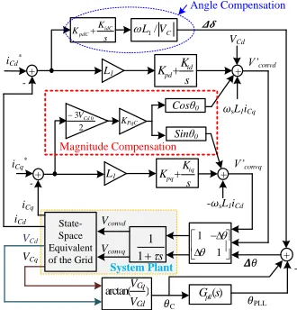
With the proposed current error based compensation control in Section II, a comprehensive small-signal analytical model is established based on the block diagram shown in Fig.
ΔId
+ _
Δδ Angle Compensation
Classical Vector Control
Vconvd
iCd
iCd*
ΔIq + _
Δ|Vconv| Magnitude
Compensation Classical Vector
Control
Vconvq
iCq iCq*
L1
R1
VDC
VS
Vconv
PLL IC V
C
iCq
iCq* abc
dq
VCd
VCq
|VC|* PWM
|VC|
+ _ + P*
2 3VCd
Lead-Lag
s T
s T
2 1
1 1
K y
x
+ |Vconv| r Vconvd*
Vconvq*
Current vector control
iCd
abc dq θ
PI +
+ VCq
VCd iCd*
iCd* iCd
+ -P
iCq* iCq*
L2
R2
Magnitude Compensation
Angle Compensation
θadj
θadj
iCq conv
V
-Cd
V 3
2
C V L1/
[image:4.612.48.298.246.475.2]5 including the dynamics of PLL, modulation delay and grid impedances [28]. In Fig. 5, KpdC and KidC refer to the
proportional and integral gains of angle compensation respectively; KpqC the proportional gain of the magnitude
compensation; VCd0 and θ0 the static operational point of VCd
and θ respectively; Kpd, Kid the PI regulator gains of the
conventional d-axis current loop; Kpq, Kiq the PI regulator
gains of the conventional q-axis current loop.
Fig. 5. Block diagram of the VSC analytical model in frequency domain The model is established in d-q reference frame, which is synchronized with the local capacitor voltage in this paper. The dynamics brought about by PLL is expressed as an angle error between its output 𝜃PLLand the real capacitor angle 𝜃c.
The process of PLL is considered using 𝐺𝑝𝑙𝑙(𝑠) as the closed- loop transfer function, which can be expressed as
𝐺𝑃𝐿𝐿(𝑠) =
𝑘𝑝𝑃𝐿𝐿𝑠+𝑘𝑖𝑃𝐿𝐿
𝑠2+𝑘
𝑝𝑃𝐿𝐿𝑠+𝑘𝑖𝑃𝐿𝐿
(9)
where kpPLL and kiPLL are the proportional and integral gains
respectively. Using Taylor Expansion, the process of arctan(VCq/VCd) in Fig. 5 can be linearized as
) ( 1 1 ) ( ) (arctan ) ( arctan 0 0 2 0 2 0 0 0 0 0 0 0 0 0 Cd Cq Cd Cq Cd Cq Cd Cq Cd Cq Cd Cq V V V V Cd Cq Cd Cq Cd Cq Cd Cq V V V V V V V V V V V V V V V V d d V V V V Cd Cq Cd Cq (10)
A sub-model based on state space model is established for the impedances of VSC output and the main grid as [28].
𝑥̇ = 𝐴𝑥 + 𝐵𝑢 (11)
where
𝑥 = [𝑖1𝑑 𝑖1𝑞𝑉𝐶𝑑 𝑉𝐶𝑞 𝑖2𝑑 𝑖2𝑞]𝑇; 𝑢 = [𝑉𝑠𝑑 𝑉𝑠𝑞 𝑉𝑐𝑜𝑛𝑣𝑑 𝑉𝑐𝑜𝑛𝑣𝑞]𝑇
(12)
𝐴 = 𝜔𝑏∗
[
−𝑅𝐿11 𝜔 −
1
𝐿1 0 0 0
−𝜔 −𝑅1
𝐿1 0 −
1
𝐿1 0 0
1
𝐶 0 0 −𝜔 −
1
𝐶 0
0 1
𝐶 𝜔 0 0 −
1 𝐶
0 0 𝐿1
2 0 −
𝑅2
𝐿2 𝜔
0 0 0 1
𝐿2 −𝜔 −
𝑅2
𝐿2]
;
𝐵 = 𝜔𝑏∗
[
0 0 𝐿11 0
0 0 0 1
𝐿1
0 0 0 0
0 0 0 0
−1
𝐿2 0 0 0
0 −1
𝐿2 0 0 ]
[image:5.612.89.254.152.324.2](13)
TABLE I. System initial parameters
Transformer Inductance 𝑙𝑡𝑥 0.1 pu
Transformer ratio 𝑁𝑡𝑥 0.69/33kV
VSC nominal voltage 𝑉𝑛 690 V
Reactor inductance 𝐿1 0.2 pu
Filter Capacitance 𝐶𝑓 0.1 pu
Current controller proportional gains Kpd = Kpq 141 πL1 Current controller integral gains Kid = Kiq 10000π2𝐿1
PLL proportional gain 𝑘𝑝𝑃𝐿𝐿 178
PLL Integral gain 𝑘𝑖 𝑃𝐿𝐿 3947
Voltage controller droop gain K 12
Short Circuit Ratio SCR 1
Angle compensation proportional gain KpdC 0.2 Angle compensation integral gain KidC 4
Magnitude compensation gain KpqC 0.2
Lead-lag filter nominator time constant
𝑇1 0.002s
Lead-lag filter denominator time constant
𝑇2 0.01s
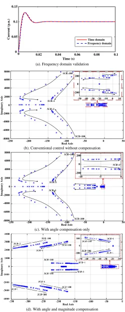
To validate the frequency domain model, a comparison of step response test is performed in Fig. 6(a), where the step response based on the frequency domain model in Fig. 5 is compared with result from the average model from Fig. 4 (linearized when the current is zero). The reference frame angles used for both step response tests are aligned with the capacitor voltage. A current step order of 0.1 p.u. is given at Time = 0 s for both models. It shows that both results correspond to each other well with a trivial difference, which is due to the slight deviation of static operation point of the frequency domain model.
Based on the block diagram in Fig. 5, root locus analysis is carried out for the closed-loop of the d-axis current with various SCR values. Setting the generated power and capacitor voltage at rated value with the parameters set shown in Table I, the static power flow solution when the d-axis is aligned with the capacitor voltage can be obtained as
T
x
0
[
1.0004,
-
0.1128,1,
0,
0.9999,
-
0.2188
]
T
u
0
[
0.9742,
-
0.2257,
1.0824,
0.1960
]
iCd*
iCq*
--+ + + + iCd iCq VCd VCq
𝜔sL1iCq
+ 𝜃 1 1 L1 ) (s Gpll State- Space Equivalent of the Grid
) arctan( V V Cd Cq s K K iq pq L1 s K K id pd 2 3VCd0
K PqC Cosθ0 Sinθ0 V’convd Vconvq s K K idC pdC Angle Compensation Magnitude Compensation VCd V’convq 𝜃PLL 𝜃C -Vconvd
-𝜔sL1iCd
Electrical and Electronic Engineering Copyright. The copy of record is available at IEEE Xplore Digital Library.
(a). Frequency domain validation
(b). Conventional control without compensation
(c). With angle compensation only
[image:6.612.48.299.44.666.2](d). With angle and magnitude compensation Fig. 6. Root locus (rated current, SCR = 100 ~ 1)
By adding the proposed control of active current with angle compensation only, the corresponding root locus of the main poles shown in Fig. 6(c) reveals that the main poles are kept within the left plane even when the grid is very weak as the
SCR goes as small as 1. This demonstrates that the proposed
angle compensation control can stabilize the system with current loop in very weak grid regardless the variations of
SCR. The stability has been significantly improved though, the damping is relatively poor when the grid strength is as weak as
SCR = 1. It can be seen in Fig. 6(c) that the real component of the main pole can reach around 0.5 while the absolute value of the imaginary part is more than 100 at SCR = 1 point, giving a poor damping ratio lower than 0.0025. This shows that the proposed current-error based angular compensation can stabilize the system by pushing the poles to the left plane, which is a significant improvement from the unstable cases from conventional control. However, when the SCR is close to 1, the damping is relatively poor.
The root locus of the main poles for classical vector control shown in Fig. 1 can be obtained as Fig. 6(b) when the proposed compensation control is not in place. From Fig. 6(b), it can be seen that the main poles move towards and enter the right plane ( SCR between 1 and 2) when the SCR value decreases from 100 to 1, which shows that classical vector control tends to become poorly damped or even unstable when the grid connection becomes very weak. The corresponding natural frequency of the main pole is also around 40 Hz when the SCR is close to 1, which corresponds well to the time domain analysis in Fig. 3.
0 0.05 0.1 0.15 0.2 0.25 0.3 0.35
-1 0 1 2 3
From: Step To: Demux11/1 Step Response
Time (seconds)
A
m
p
lit
u
d
e
Improved controller Classic current controller
0 0.05 0.1 0.15 0.2 0.25 0.3 0.35
Time (s)
A
m
pl
it
ud
e
0
[image:6.612.318.554.338.455.2]-1 1 2 3
Fig. 7. Step response test for SCR = 1
The magnitude compensation is added in addition to the angle compensation and the corresponding root locus of the main poles is shown in Fig. 6(d). A better damping performance of the main poles can be seen in Fig. 6(d) that the damping ratio of the main pole at SCR = 1 can reach as much as 0.4, which is approximately 160 times larger than in Fig. 6 (c). Obviously, this shows that magnitude compensation can further improve system damping when the grid is very weak.
Based on the frequency domain model, a unit step response of active current of SCR = 1 is plotted in Fig. 7 for the frequency domain model. As illustrated by the solid line in Fig. 7, the step response does not converge when there is no compensation; meanwhile, the response converges when the proposed angle and magnitude compensations are added. This result shows that the proposed control is also able to provide a satisfactory performance step-up response. As it is practically unlikely to have a scenario of large power step-up for wind power generation applications, the step test in Fig. 7 is more of an illustration of system performance. Ramp test, which is more applicable in practical implementation, will be carried out in the comprehensive time domain simulations in Section IV.
0 0.02 0.04 0.06 0.08 0.1
Time (s) 0
0.05 0.1 0.15
C
u
rr
en
t
(p
.u
.)
Time domain Frequency domain
-250 -200 -150 -100 -50 0 50 8000
6000
4000
2000
0
-2000
-4000
-6000
-8000
200
-200 0
-50 -40 -30 -20 -10 0 10
SCR=100 SCR=1
SCR=100
SCR=1
Real Axis
Im
a
g
in
a
ry
A
x
is
8000
6000
4000
2000
0
-2000
-4000
-6000
-8000
-250 -200 -150 -100 -50 0 50
SCR=100 SCR=1
SCR=100
SCR=1
200
-200 0
-10 -5 0
Real Axis
Im
a
g
in
a
r
y
A
x
is
SCR=1
Im
a
g
in
a
ry
A
x
is
Real Axis
IV. TIME DOMAIN CASE STUDIES
In this section, the proposed control is tested for the system shown in Fig. 1 with time domain simulation for different cases including power ramp, parallel converters and AC fault conditions. The initial parameter settings are as shown in Table I. Classical average model of VSC [10] is used for time domain simulations with Matlab/Simulink. The compensation control settings are kept unchanged throughout this section to demonstrate the robustness.
A. Power ramp test
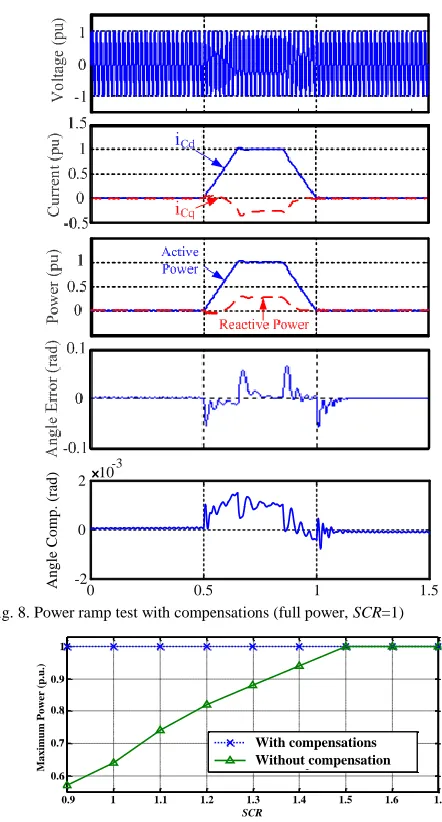
Power ramp test using the proposed control is performed with a lumped VSC model representing a cluster of 10 wind turbines each rated at 6 MW and SCR = 1. To avoid the dynamics brought by closed power loops, open loop power control is used in this section. The simulation results are shown in Fig. 8 where active power is ramped up at 0.5 s from 0 to 1 p.u. at a rate of 6 p.u. /s and down to 0 again. It can be seen that the AC voltage is well maintained and the active power is stable throughout this test, which proves the effectiveness of the proposed control. It can also be noted that the angle error between the real and detected angles after compensation is kept very close to 0 during the test.
As is shown, the compensation component tends to counteract the angle detection error when the power is changing and it converges to 0 at steady state which demonstrates that the compensation itself does not cause angular deviation from the real voltage at the connection point for the coordinate transformations. This means that the proposed compensation can effectively help the PLL to track the real angle without introducing an angular offset to the coordinate transformations. The active and reactive components can still be well decoupled based on capacitor voltage oriented transformation.
Based on similar ramp tests, the power inversion capability for different SCR values is summarized in Fig. 9. By using the classical vector control, the maximum power transferring capability will be less than 1 p.u. when SCR is lower than 1.5 and decrease to 0.63 p.u. as SCR drops to 1. On the contrary,
shown in Fig. 9 again, the active power transferring capability can be maintained at 1 p.u. using the proposed compensation control with an SCR down to 0.9, which can be tested with similar operation scenario in Fig. 8. In addition, since the proposed angular compensation is placed on the output of PLL, it is not sensitive to the internal implementations of PLL. More widely, the proposed compensations can enhance the damping for all the VSC control schemes involving angular detections for reference frame and the magnitude compensation can be used for control schemes involving voltage magnitude as a part of output as well. The power rectification capability can be lower than inversion according to the variations of transmission line resistance, power flow constraints, etc. [32], but it is not within the scope due to the context of this paper.
B. Multiple parallel VSC test
As a practical wind farm, of 60 MW for instance, usually consists of multiple parallel turbines and clusters, simulation considering two parallel lump VSCs is carried out to illustrate the effectiveness for multiple converter conditions. Keeping
[image:7.612.319.540.98.509.2]SCR at 1, both VSC ratings are set at 0.5 p.u. of the rated power of the wind farm. Ramp power orders are given to the VSCs one after another to study the power transferring capability of the whole wind farm.
Fig. 8. Power ramp test with compensations (full power, SCR=1)
Fig. 9. Power inversion capability
Using conventional vector current control, the result is shown in Fig. 10 (a) where the output power of VSC 1 is ramped up from 0 to 0.5 p.u. at 0.05 s at a rate of 2.5 p.u./s. VSC 2 starts the same ramp from 0.15 s. Both power starts to oscillate before VSC 2 reaches its rated value as is shown in Fig. 10 (a). In other words, the wind farm is not capable of transferring the full power. On the contrary, employing the proposed control method for both VSCs, full power is transferable as shown in Fig. 10(b) with no oscillation. This test shows that the proposed control also have a significant effect for multiple VSCs cases and the proposed control does not introduce circulating power.
C. AC fault test
As cited in Section I and II, the advantage of the proposed control is that it is capable of continuously controlling the VSC current during large voltage perturbations with no need for control mode switching. Three-phase fault condition is considered to be one of the most severe cases and hence the
0 0.5 1 1.5
-2 0 2 10
-3
A
n
g
le
C
o
m
p
.
(r
ad
)
0.9 1 1.1 1.2 1.3 1.4 1.5 1.6 1.7
0.6 0.7 0.8 0.9 1
Short Circuit Ratio (SCR)
P
ow
er
t
ra
ns
fe
r
ca
pa
bi
li
ty
(pu
)
With split current control Without split current control
0.9 1 1.1 1.2 1.3 1.4 1.5 1.6 1.7
SCR
M
a
x
im
u
m
P
o
w
er
(
p
.u
.)
1
0.9
0.8
0.7
0.6
Electrical and Electronic Engineering Copyright. The copy of record is available at IEEE Xplore Digital Library. relevant tests are carried out in this section to demonstrate its
effectiveness and robustness with various SCR values, which is shown in Fig. 11.
(a). Conventional control without compensations
[image:8.612.64.281.92.482.2](b). With angular and magnitude compensations Fig. 10. Parallel VSC power ramp test (full power, SCR=1)
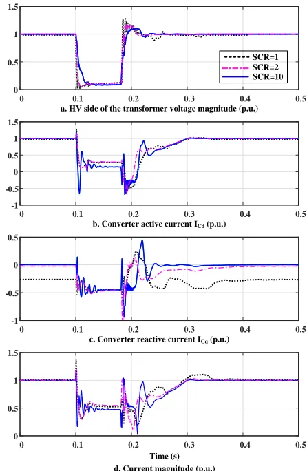
The simulation results for SCR = 1, 2, and10are compared in Fig. 11(a). The VSC exports rated active power prior to the three-phase AC fault, for the most serious case concern, using the proposed controller at the start. As this case study aims to test the specific current-limitingcompatibility of the proposed control during a large transient, the DC side voltage variation during the transient is assumed to be well maintained by the turbine-side converter and damping resistance throughout the transient [31].
The tests start from full power delivery from 0 s for the cases of SCR = 1, 2 and 10 respectively, which is shown in Fig. 11. At 0.1 s, a three-phase AC fault occurs, which forces the AC voltages drop to almost 0 immediately. Taking advantage of the current loop, the VSC continues controlling the AC current and the maximum instant current overshoot is approximately 0.3 p.u. for the case of SCR = 1 and well regulated under 1.1 p.u. thereafter. Similar results can be found for SCR = 2 and 10 cases as shown in Fig. 11, both with current magnitude well capped during the identical transient.
For such a weak network, in order to reduce AC voltage overshoot after fault clearance, a voltage-dependent current
[image:8.612.327.550.138.480.2]limit (VDCL) is employed as shown in Fig. 12 [27]. The VSC active current is capped according to voltage level during the AC fault. Meanwhile, a reactive current limit of 0.5 pu is also set during the fault. It can be seen that the VSC current components in both the d and q axis are well controlled within their limits during the fault with no need for current control mode switching.
Fig. 11. Transient performance with angular and magnitude compensations At 0.18 s, the fault is cleared. The active power is recovered according to Fig. 12 for SCR = 1 case. As the fault clearance introduces voltage oscillation due to the very weak grid strength, there are some currents variations though the VSC current remains within its rating throughout the recovering process. Once the voltage returns to its nominal values in approximately 0.12 s after clearance, the VSC also resumes to its pre-fault operational state. Similar performance can be found for SCR = 2 and 10 cases in Fig. 12 though with different current/voltage variations.
From Fig. 11, it can be found that the currents can be well regulated in the case of either SCR = 1, 2 or 10, which demonstrate that the proposed control can well control the currents either in steady state and transients. Satisfactory current regulations can be achieved with variable SCR values using the same control parameters, which demonstrate that the proposed control strategy is not sensitive to SCR variations in terms of steady state operations and transient current regulations.
0 0.1 0.2 0.3 0.4 Time (s)
-1.5 -1 -0.5 0 0.5 1
VSC 1
VSC 2
0.5
0 0.1 0.2 0.3 0.4 0.5 Time (s)
0.75 1 1.25 1.5 0
A
ct
iv
e
p
o
w
er
(
p
.u
.)
P
C
C
V
o
lt
a
g
e
M
a
g
it
u
d
e
(p
.u
.)
0 0.1 0.2 0.3 0.4 Time (s)
0
0.5 VSC 1
VSC 2
0.5
0.75 1 1.25 1.5
0 0.1 0.2 0.3 0.4 0.5 Time (s)
A
ct
iv
e
p
o
w
er
(
p
.u
.)
P
C
C
V
o
lt
a
g
e
M
a
g
it
u
d
e
(p
.u
.)
a. HV side of the transformer voltage magnitude (p.u.)
0 0.1 0.2 0.3 0.4 0.5
0 0.5 1 1.5
0 0.1 0.2 0.3 0.4 0.5
-1 -0.5 0 0.5 1 1.5
0 0.1 0.2 0.3 0.4 0.5
-1 -0.5 0 0.5
0 0.1 0.2 0.3 0.4 0.5
0 0.5 1 1.5
SCR=1
SCR=10 SCR=2
b. Converter active current ICd (p.u.)
c. Converter reactive current ICq (p.u.)
V. DISCUSSIONS ON THE PLL IMPLEMENTATIONS
The investigation on the interaction between closed-loop current control and synchronization method, PLL in particular, is based on the most prevalent Synchronous Reference Frame PLL (SRF-PLL). The proposed compensation is applied toand validated with a system using SRF-PLL as well. As there are a large variety of derived implementations of PLL, namely moving average filter-based PLL [35], Notch filter based PLL [36], delayed signal cancellation based PLL [37], etc. [38], the corresponding dynamics may vary case by case. Thus, the detailed exhaustive analytical comparisons of PLL are not presented in this paper due to the limited pages and time availability. However, the analytical method presented in this paper can still be appliedto investigate the interaction between a certain PLL and the current control loop. Furthermore, since the proposed compensations do not involve any internal modification of PLL itself, they can still be used to enhance system damping with different PLL implementations.
V1 V2
VAC
Isd
Imin 1.0
1.0
Fig. 12. Voltage dependent active current limit
VI. CONCLUSION
In this paper, a current error based compensation control is proposed for VSC integration to weak AC grid with closed-loop current regulation. Compensation regulations can be applied by taking advantage of the small-signal linear relationship between active and reactive current against converter angle and voltage magnitude,respectively.
Based on frequency domain analysis, the proposed active current compensation can significantly improve stability performance by enhancing the system damping in addition to reactive power compensation.
Time domain simulations show that the proposed control can significantly increase the power transferring capability of a VSC generation from weak grid point. Case studies also demonstrate that the proposed current control can work well both in single or multiple converter situations, and during a severe AC fault. It can further benefit from its simple implementation and robustness against grid strength variations. Since the proposed strategy does not change the internal configuration of a PLL, it generally applies to all kinds of VSC control involving reference frame transformation based on angular detection.
REFERENCES
[1] K. Givaki, M. Parker, and P. Jamieson, "Estimation of the power electronic converter lifetime in fully rated converter wind turbine for onshore and offshore wind farms," in proc.7th IET International Conference on Power Electronics, Machines and Drives (PEMD 2014), , Manchester, 2014.
[2] E. W. E. Association, "The European offshore wind industry - key trends and statistics 2015," European Wind Energy Association2016.
[3] "IEEE Guide for Planning DC Links Terminating at AC Locations Having Low Short-Circuit Capacities," IEEE Std 1204-1997, pp. 1-216, 1997.
[4] S. L. Lorenzen, A. B. Nielsen, and L. Bede, "Control of a grid connected converter during weak grid conditions," in Proc. 2016 IEEE 7th International Symposium on Power Electronics for Distributed Generation Systems (PEDG), 2016, pp. 1-6.
[5] S. Grunau and F. W. Fuchs, "Effect of Wind-Energy Power Injection into Weak Grids," EWEA 2012 Annual Event, Copenhagen, 2012. [6] Y. Xibo, W. Fei, D. Boroyevich, L. Yongdong, and R. Burgos,
"DC-link Voltage Control of a Full Power Converter for Wind Generator Operating in Weak-Grid Systems," IEEE Trans. Power Electron., vol. 24, pp. 2178-2192, 2009.
[7] N. P. W. Strachan and D. Jovcic, "Stability of a Variable-Speed Permanent Magnet Wind Generator with Weak AC Grids," IEEE Trans. Power Del., vol. 25, pp. 2779-2788, 2010.
[8] K. Givaki, D. Chen, and O. Anaya-Lara, "Stability studies of different AC collection network topologies in wind farms," Proc. IET Renewable Power Generation, London, 2016.
[9] L. Xu, D. Zhi, and L. Yao, "Direct Power Control of Grid Connected Voltage Source Converters," in Proc. IEEE Power Engineering Society General Meeting, Tampa, 2007.
[10] A. Egea-Alvarez, S. Fekriasl, F. Hassan, and O. Gomis-Bellmunt, "Advanced vector control for voltage source converters connected to weak grids," IEEE Trans. Power Syst., vol. 30, pp. 3072-3081, 2015. [11] L. Zhang, L. Harnefors, and H. P. Nee, "Power-Synchronization
Control of Grid-Connected Voltage-Source Converters," IEEE Trans. Power Syst., vol. 25, pp. 809-820, 2010.
[12] L. Zhang, L. Harnefors, and H. P. Nee, "Interconnection of Two Very Weak AC Systems by VSC-HVDC Links Using Power-Synchronization Control," IEEE Trans. Power Syst., vol. 26, pp. 344-355, 2011.
[13] L. Harnefors, M. Bongiorno, and S. Lundberg, "Input-Admittance Calculation and Shaping for Controlled Voltage-Source Converters," IEEE Trans. Ind. Electron., vol. 54, pp. 3323-3334, 2007.
[14] D. Dong, B. Wen, D. Boroyevich, P. Mattavelli, and Y. Xue, "Analysis of Phase-Locked Loop Low-Frequency Stability in Three-Phase Grid-Connected Power Converters Considering Impedance Interactions," IEEE Trans. on Ind. Electron., vol. 62, pp. 310-321, 2015.
[15] J. Z. Zhou, D. Hui, F. Shengtao, Z. Yi, and A. M. Gole, "Impact of Short-Circuit Ratio and Phase-Locked-Loop Parameters on the Small-Signal Behavior of a VSC-HVDC Converter," IEEE Trans. Power Del., vol. 29, pp. 2287-2296, 2014.
[16] D. Jovcic, L. A. Lamont, and L. Xu, "VSC transmission model for analytical studies," in Proc. IEEE Power Engineering Society General Meeting, 2003.
[17] B. H. Kim and S. K. Sul, "Stability Oriented Design of Frequency Drift Anti-islanding and Phase-Locked Loop under Weak Grid”, early access, IEEE Journal Emerg. Sel. Topics Power Electron., 2016. [18] B. Wen, D. Boroyevich, R. Burgos, P. Mattavelli, and Z. Shen,
"Analysis of D-Q Small-Signal Impedance of Grid-Tied Inverters," IEEE Trans. Power Electron., vol. 31, pp. 675-687, 2016.
[19] J. A. Suul, S. D. Arco, P. Rodr, xed, guez, and M. Molinas, "Impedance-compensated grid synchronisation for extending the stability range of weak grids with voltage source converters," IET Generation, Transmission & Distribution, vol. 10, pp. 1315-1326, 2016.
[20] A. Egea-Alvarez, C. Barker, F. Hassan, and O. Gomis-Bellmunt, "Capability curves of a VSC-HVDC connected to a weak AC grid considering stability and power limits," in Proc. 11th IET International Conference on AC and DC Power Transmission, , 2015, pp. 1-5. [21] J. Z. Zhou and A. M. Gole, "VSC transmission limitations imposed by
AC system strength and AC impedance characteristics," in Proc. 10th IET International Conference on AC and DC Power Transmission, 2012, pp. 1-6.
[22] J. Driesen and K. Visscher, "Virtual synchronous generators," in Proc. IEEE Power and Energy Society General Meeting, 2008, pp. 1-3. [23] H. P. Beck and R. Hesse, "Virtual synchronous machine," in Proc. 9th
International Conference on Electrical Power Quality and Utilisation (EPQU 2007) 2007, pp. 1-6.
Electrical and Electronic Engineering Copyright. The copy of record is available at IEEE Xplore Digital Library. [25] Q.-C. Zhong and Weiss, "Synchronverters: Inverters that mimic
synchronous generators," IEEE Trans. Ind. Electron., vol. 58, pp. 1259-1267, 2011.
[26] M. F. M. Arani and Y. A. R. I. Mohamed, "Analysis and Performance Enhancement of Vector-Controlled VSC in HVDC Links Connected to Very Weak Grids," IEEE Trans. Power Syst., vol. PP, pp. 1-10, 2016. [27] L. Xu, L. Yao, and C. Sasse, "Grid Integration of Large DFIG-Based
Wind Farms Using VSC Transmission," IEEE Trans. Power Syst., vol. 22, pp. 976-984, 2007.
[28] K. Givaki and L. Xu, "Stability analysis of large wind farms connected to weak AC networks incorporating PLL dynamics," in Proc. International Conference on Renewable Power Generation 2015, pp. 1-6.
[29] A. Yazdani and R. Iravani, “Voltage-Sourced Converters in Power Systems: Modeling, Control And Applications”, John Wiley & Sons, 2010.
[30] D. Chen and L. Xu, "Autonomous DC Voltage Control of a DC Microgrid with Multiple Slack Terminals," IEEE Trans. Power Syst., vol.27, pp.1897-1905, 2012.
[31] H. N. Villegas Pico and D. C. Aliprantis, "Voltage Ride-Through Capability Verification of Wind Turbines With Fully-Rated Converters Using Reachability Analysis," IEEE Trans. Energy Conv., vol. 29, no. 2, pp. 392-405, June 2014.
[32] B. Yuan, J. Xu, C. Zhao, Y. Yuan," An Improved Phase-Locked-Loop Control with Alternative Damping Factors for VSC Connected to Weak AC System," Journal of Control Science and Engineering, Volume 2016
[33] W. Wang, A. Beddard, M. Barnes, O. Marjanovic, "Analysis of Active Power Control for VSC–HVDC" in IEEE Transactions on Power Delivery, Vol. 29, No. 4, August 2014, pp. 1978-1988
[34] Texas Instrument, "TMS320F2833x, TMS320F2823x Digital Signal Controllers (DSCs), "October 2016
[35] S. Golestan, M. Ramezani, J. M. Guerrero, F. D. Freijedo, and M. Monfared, “Moving average filter based phase-locked loops: Performance analysis and design guidelines,” IEEE Trans. Power Electron., vol. 29, no. 6, pp. 2750–2763, Jun. 2014.
[36] F. D. Freijedo, J. Doval-Gandoy, O. Lopez, and E. Acha, “Tuning of phase-locked loops for power converters under distorted utility conditions,” IEEE Trans. Ind. Appl., vol. 45, no. 6, pp. 2039–2047, Nov./Dec. 2009.
[37] F. A. S. Neves, M. C. Cavalcanti, H. E. P. de Souza, F. Bradaschia, E. J. Bueno, and M. Rizo, “A generalized delayed signal cancellation method for detecting fundamental-frequency positive-sequence threephase signals,” IEEE Trans. Power Del., vol. 25, no. 3, pp. 1816– 1825, Jul. 2010.
[38] S. Golestan, J. M. Guerrero and J. C. Vasquez, "Three-Phase PLLs: A Review of Recent Advances," IEEE Trans. Power Electron., vol. 32, no. 3, pp. 1894-1907, March 2017.
VII. BIOGRAPHIES
Kamyab Givaki received the MSc and PhD degrees in electrical and electronic engineering from University of Strathclyde, Glasgow, UK, in 2012 and 2017, respectively.
Since 2017, he was with University of Strathclyde working as a research associate in Glasgow, UK. He is currently with the Edinburgh Napier University, Edinburgh, UK. He previously worked in Glasgow Caledonian University, Glasgow.
His research interests include HVDC transmission system, wind energy generation and grid integration, and application of power electronics to power systems.
Dong Chen received the B.Eng. degree from Southeast University, Nanjing, China, in 2006, M.Sc. degree from Zhejiang University, Hangzhou, China, in 2008 and Ph.D. degree from the Queen’s University of Belfast, Belfast, UK in 2012.
He is currently with the School of Engineering and Built Environment, Glasgow Caledonian University. He was previously with Strathclyde University, Glasgow, UK and Guodian Nanjing Automation, Co. Ltd., Nanjing, China. His research interest includes: power electronics applications to power systems, DC microgrid, distribution power system and motion control.
Lie Xu (M’03–SM’06) received the B.Sc. degree in Mechatronics from Zhejiang University, Hangzhou, China, in 1993, and the Ph.D. degree in Electrical Engineering from the University of Sheffield, Sheffield, UK, in 2000.