The Effect of Elasto-Plastic Properties of Materials on their
Formability by Flow Forming
Olga I. Bylyaa, Timur Khismatullina, Paul Blackwellb* and Rudolf A. Vasinc
a Advanced Forming Research Centre, University of Strathclyde, 85 Inchinnan Drive, Inchinnan, Renfrew PA4
9LJ, United Kingdom
b Mechanical & Aerospace Engineering, University of Strathclyde, James Weir Building, 75 Montrose Street,
G1 1XJ
c Institute of Mechanics, Lomonosov Moscow State University, 2 Michurinsky Prospect, Moscow, Russia
Abstract
FEA process modelling, which has seen plenty of development in recent decades, has
significantly simplified and broadened our capabilities for designing and optimising metal
forming processes. It has become relatively easy to find the stress-strain state at any point and
instant in the process, analyse the kinematics of metal flow or test different fracture criteria.
However, it is frequently the case that all this information cannot compensate for the lack of a
fundamental understanding of the process. Flow forming is a case in point. Although much
research has been carried out since the 1960’s and has resulted in considerable industrial
experience, still many aspects remain as “know how” and many basic questions do not have
exact answers. This work reported herein is focused on the role of the elasto-plastic
properties of a material with respect to its use in flow forming. Can the flow formability of a
material be assessed using data from a uniaxial tensile test? If there exists the possibility of
tailoring mechanical properties by heat treatment, what should be prioritised?
Keywords: Flow forming, finite element (FE) modelling, heat treatment, complex loading.
*
1. Introduction
Flow forming (or tube spinning) is one of the incremental bulk metal forming processes, used
for the manufacturing of tubular parts. It is often carried out at room temperature. Although it
benefits from the advantages of its incremental nature, flow forming is quite a difficult
process to optimise. Plewinski and Denger (2009) pointed out that the limited contact spot
between the rollers and deformed part significantly reduces the overall loads and provides the
ability to form quite large parts from a wide range of difficult-to deform materials with a
relatively a small capacity forming machine. However, this advantage can become a problem
during the development of the forming technology. The small contact area and low material
strain rate sensitivity typical at room temperature can generate a limited ability to control the
material flow. For this reason the flow forming process appears to be very sensitive to not
only the major control parameters of the process such as the speed of the mandrel, axial feed
of the rollers and thickness reduction, but also to less evident ones such as the radial and axial
roller offsets and their geometry.
A review of research carried out on incremental forming in the period between 1960-1980
was offered by Kalpakjian et al (1982). However, much of this work was focused on shear
spinning and although this and flow forming have some similarities, the difference in the
nature of deformation is quite significant, so in this paper attention will be focused only on
flow forming (tube spinning). Bennich (1976) published work containing a detailed
examination of the mechanics of flow forming, illustrating his analysis with physical
modelling and predictions for microstructural development. This contributed much to
understanding the nature of the process and helped in establishing a correlation between
process parameters and loads as well as the deformation observed in the process. However,
such approaches for physical modelling indirectly assume that materials with different
elastic-plastic properties will behave similarly during flow forming and will have a
comparable response to changes in process parameters (e.g. increasing or decreasing feed
behaviour of a number of materials (mild steels, 6xxx Al alloys, Copper) which had a yield
stress in the range of 250-500 MPa and exhibited strong strain hardening. These metals
provided good formability, however, it is not clear that this would be true for the High
Strength Steels, Ti, Ni or Al-Li alloys, which are required in modern technological
applications. Kalpakcioglu (1964) suggested an experimental procedure which might be used
to assess the limits of formability. The usefulness of this approach is discussed in more detail
in section 4 below.
Later research focused more on the analysis of different geometrical, kinematic and dynamic
characteristics of the Flow Forming process without much discussion about how the results
obtained might apply to materials with different types of elastic-plastic behaviour. The work
of Ma (1993) was devoted to finding the optimal angle of attack for the tooling in tube
spinning. The work of M.J. Roy et al (2015); (2010); (2009) focused on analyses of the
contact between tools and workpiece and investigation of the nature of the strain distribution
using finite element (FEM) simulation along with direct experimental methods.
As far as the authors are aware, the question about the influence of the elastic-plastic
properties of the workpiece material was indirectly touched on in only two papers. Rajan et
al. (2002) analysed the effect of the heat treatment of AISI 4130 steel on flow formability and
ten years later similar work was repeated by Podder et al. (2012) for AISI 4340 steel. In both
cases three heat treatments were studied: annealing, normalizing and hardening & tempering
for AISI 4130; annealing, spheroidizing, hardening & tempering for AISI 4340. In the case of
the 4130 steel, the authors obtained similar shapes of stress-strain curves, differing only in
scale – the yield (proof stress) changed from about 400 MPa to 800 MPa, but the level of
strain hardening and elongation remained the same. For 4340 the situation was different – the
annealed steal had the highest strain hardening, the hardened & tempered condition the
lowest. The main purpose of both papers was to find the effect of heat treatment on the final
mechanical properties of formed tubes. Flow-formability was mentioned only in Podder et al
geometric ovality. This is a very different vision of flow formability than that proposed by
Kalpakjian et al (1982), which shows that even the definition of flow formability (or tube
spinnability) is not self-evident and requires further discussion.
In order to design and optimise the process the role of the elastic-plastic properties of a
material needs to be better understood. There are two pertinent aspects here. Firstly, many
materials allow variation of their mechanical properties via different heat treatments.
Secondary, when choosing which material to use for a part there are materials with different
costs, but relatively close final properties. The designer has to consider which material or
heat treatment should be preferred if flow forming is kept in mind as a manufacturing
process. In Fig. 1a. it can be seen that the two martensitic precipitation-hardening stainless
steels 15-5 PH® and 17-4 PH® have relatively similar mechanical properties and a wide
range of possible heat treatments, but normally 15-5 PH® is costlier than 17-4 PH®. Both
steels have high strength, are of interest for aerospace applications and are difficult to deform,
which may make incremental bulk forming attractive. To optimise material and process
choice further understanding is therefore useful.
The mechanics of flow forming are complicated. There is a combination of local loading (in
the area of the tooling) and general deformation of the preform as a shell (with constraints of
different types and shifting loads). This process is characterised with strongly triaxial stress
states, non-monotonous loading with the possibility of cyclic changes in load from tensile to
compressive and continuous changing of principal loading directions. The question then
arises of which theory of plasticity and which fracture models are the most suitable for an
adequate description of the process and what mechanical testing methodology is necessary
and sufficient to calibrate these models? Here we start from the standard tensile properties of
the material and some classical 2D (two-dimensional) models. If some clarity about the basic
logic of the process can be achieved at this level, then the analysis can be expanded to more
As a first approach, any uniaxial tensile stress-strain diagram (or the universal equivalent
stress-strain curve, if it exists) can be characterized with the following five main parameters,
see Fig. 1b:
1. E – Young’s modulus,
2. σy – yield (proof) stress,
3. ϒ – normalised strain hardening/softening factor, where:
1 (in which is
stress and is strain), which can be associated with the original absolute value of the
tangential modulus 0 .
4. σu – ultimate stress,
5. δ – limiting tensile elongation.
Additionally, the tensile test gives us the value of ψ – the maximum area reduction.
This is what normally is known about a material before trying to optimise the process
parameters. In this paper an attempt is made to understand how these parameters affect the
behaviour of the material during flow forming.
a) b)
Fig. 1. a) The details of the stress-strain curves of martensitic AK steel 15-5 PH® and 17-4
PH® with typical heat treatments “15-5 PH data sheet” (2007), “17-4 PH data sheet” (2007);
[image:5.595.74.521.490.622.2]2. Experimental procedure and numerical simulations
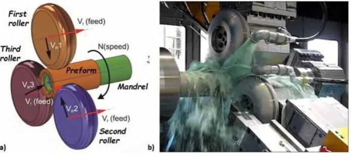
The scheme of a standard flow forming setup is shown in Fig. 2a. The mandrel is directly
driven and rotates at a constant rate. The workpiece (WP) is formed over the mandrel and is
fixed to it on one side with the tailstock. The preform rotates together with the mandrel,
though the material is free to expand or flow along the mandrel. Three rollers, located at an
equal angle of 120° with each other, are free to rotate about their axis and are driven by the
friction developed at the contact with the WP (hence, partial slipping is possible). These three
rollers travel parallel to the axis of the shaft and converge in the radial direction to shape the
required profile of the WP; the motions of the rollers are controlled using a CNC program.
For the present work flow forming trials were performed with a WF STR 600-3/6 flow
forming machine shown in Fig. 2b.
Fig. 2. a) The scheme of a standard flow forming setup; b) the Flow Former used by the
authors; WF STR 600-3/6.
An FEA simulation of the flow forming operation was made using QForm metal-forming
modelling software. It was assumed that material of the WP exhibited elastic-plastic isotropic
hardening. It remains an open question whether isotropic hardening gives an acceptable level
of simulation accuracy, or, due to a certain amount of cyclic loading in the nature of the
process, some variant of the translation-hardening plastic model should be used, e.g. that
[image:6.595.82.430.394.549.2]paper. Having as the main aim the understanding of the “logic” of the process and obtaining
some general assessments, the simulation results are used here only for supportive and
illustrative purposes and do not pretend to have predictive preciseness; this would require
more accurate calibration and validation of the constitutive model used.
The kinematic scheme in the model of the process followed that shown in Fig. 2a. The
mandrel and preform were directly driven (taking into account gravity and inertia effects).
The rollers were free to rotate (with a resistance torque of about 40 Nm at the shafts), the
rotation depending on the friction at the contact between the roller and preform. The only
difference between the actual process and the model was the inversion of the translatory
motion of the rollers. From the viewpoint of numerical convenience (mainly mesh
adaptation), the mandrel with the preform was assigned a translatory motion along the axis
instead of the rollers. As the feed rate in these processes was relatively low (about 2 mm/s),
this inversion is not expected to make any difference to the results of the simulation.
3. Analysis of the process logic
From a practical point of view, on the basis of experience in flow forming of different
materials, roughly three main categories can be distinguished: “good”, “intermediate” and
“poor”. “Good” materials have sufficient formability for achieving large thickness reductions
and elongations (sometimes up to 87% of thickness reduction and about 300% of relative
elongation at room temperature) without defects. Here, thickness reduction is defined
(traditionally for industrial applications) as the differential in thickness between the preform
and the final flow formed part:
% 100
0
f f R
t t t
T , Eq. (1)
where TR is thickness reduction, t0 and tf are initial and final thickness of the walls of the
logarithmic measure, e.g.
f t t0
ln , however, the industrial measure expressed by Eq.(1) will
be used in this paper for the sake of simplicity of comparison with results published in the
majority of cited papers. It should however, be borne in mind that this process involves a
series of cycles of deformation and therefore the accumulated strain will be different to that
obtained from such a simple calculation.
Materials with intermediate properties can also be flow formed, but the forming approach is
not evident and is often accompanied by the formation of different surface defects. The last
category contains materials that undergo fracture in the early stages of the forming process. It
does not always mean that these materials cannot be formed at all, but forming them (if
possible) is difficult and belongs to the category of “know-how” which is often protected by
patents. It is interesting to note that many high strength materials that would not be
considered readily deformable at room temperature e.g. HS steels, surprisingly fall into the
category of “good” materials, while well-known ductile materials, e.g. some aluminium
alloys, appear to have intermediate properties when subjected to flow forming. It might be
expected that adiabatic heating would raise the forming temperatures significantly, however
in practice large amounts of coolant are used in the process (see Fig.2b) so such effects can
be ignored – measurements have shown that the temperature after forming does not exceed
40-50 oC.
Here, the question arises as to whether it is possible to define these formability categories
more quantitatively, in some measurable units. Although, this question is very natural, and
intuitively clear to any experienced engineer dealing with flow forming, even a first approach
to an answer is not evident. As noted, Podder et al. (2012) have suggested three parameters as
a measure of flow formability: the spindle load, spring back and ovality. These parameters
may be acceptable for the comparison of a few heat treatments of the same material formed
on the same machine with the same settings, as was shown in the paper cited, but hardly
different parts. The percentage of maximum thickness reduction per (single) pass could be
considered as a candidate, as suggested in the papers of Kalpakcioglu (1964) and Kalpakjian
and Rajagopal (1982) or the ratio of maximum thickness reduction to maximum elongation
(or cross-sectional reduction) in tension – to distinguish between ductility and flow
formability. However, these parameters still depend on the process design and do not fully
express all of what is assumed in the words “good” or “intermediate”. It could be suggested
that these notions rather reflect the width of the process window – the range in which the
process parameters can safely varied about the optimal ones.
Unfortunately, being based mainly on practical observations, this classification also does not
give any a priori knowledge as to which category a material may be in until is it actually
processed. Trials required to understand this may be quite costly and may not always deliver
the required answer – sometimes failure can result from the wrong forming program rather
than the material properties. In this section, a potential correlation between the characteristics
of the tensile stress-strain diagram and flow formability of a material will be examined.
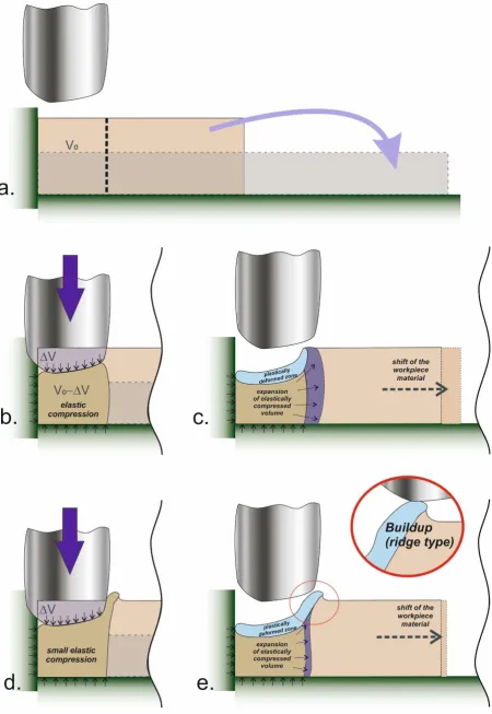
The logical scheme of the mechanism of flow forming for materials with “good” and
“intermediate” formability is presented in Fig. 3. As is shown here, the main purpose of the
flow forming process is to redistribute the original volume of the material along the mandrel.
Initially, as the roller commences to deform the material, the area located under the roller
compresses elastically (Fig. 3b). The higher the yield stress value, the more significant the
elastic volumetric compression and a larger amount of elastic strain energy is accumulated in
the deformed region. When the roller moves from this position, the load applied by it is
released and the elastically compressed material tries to restore its original volume. However,
it is restricted from behind and the bottom by the fixed constraints (Fig. 3c), and a plastically
deformed zone is formed on the top of it. This is where strain hardening plays a crucial role.
The higher the strain hardening, the bigger the difference in strength between the
almost-elastic material at the bottom and the hard plastically deformed material at the outer surface.
spring-back effect) and directs it towards the only free direction – along the mandrel. Thus, the
material expands shifting the rest of the preform along the mandrel, and the process repeats.
As a result, it is possible to achieve very large elongations due to the domination of
hydrostatic pressure during the process (this point will be discussed in more detail later in the
Fig. 3. Schematic of the principles of the flow forming mechanism for materials with “good”
In the case of soft and ductile materials, the situation is different. The elastic compression of
the material under the roller is reduced, because the force needed for plastic deformation of
such materials is low. Therefore, instead of being elastically compressed, the material, when
displaced by the roller, flows plastically towards the surface in front of the roller (Fig. 3d). To
get an improved material distribution the thickness reduction in each pass must be large –
50% or more (Fig. 3e) – which can result in cracking. At the same time, as the process
proceeds there is a build-up of plastically deformed material on top of the original material in
front of the roller and additional problems are created. As the rollers move forward these
parts of the WP tend to form flakes and chips at the contact point with the rollers; this effect
is often observed during forming of aluminium parts. Such chips get stuck to the tools or get
into the coolant stream and start to spoil the formed surfaces; see for example Fig. 4b. This
type of problem was mentioned by Nagarajan et al. (1981) as well as discussed in the earlier
works of Kalpakcioglu (1964), though those authors mainly related development of the
build-up to the roller geometry and process parameters. Some authors, e.g. Gur et al. (1982)
suggests to treat the build-ups (bulging up of the outer surface) as an indicator of unstable
process. In this investigation, a wide range of materials were formed with the same set of the
rollers and similar settings, this brought to the observation that formation of build-up depends
not only on the process parameters, but also significantly depends on material properties.
Even more, process settings have to be chosen depending on the material properties
depending on the material properties to achieve process stability.
Fig. 4. An example of parts flow formed (by the authors) at room temperature from “good”
and “intermediate” materials. a) “good” material – HS steel, preform and final part; b)
“intermediate” material – Al6082 T4, build-up of the material ahead of the roller instead of
creating longitudinal extension; c) Al6082 T4, example of chip formation in front of the
rollers.
In support of the schematic shown in Fig. 3 and to gain more insight, the difference in
materials’ behaviour can be illustrated with the classical problem of the penetration of a rigid
sphere into an elastic-plastic half-space (excluding now all the issues related to the roller
geometry). The result of the simulation of this problem (axisymmetric, 25mm sphere
penetrated with 2mm/s speed to the depth of 20 mm) is shown in Table 1 and illustrated
[image:13.595.69.532.473.715.2]schematically in Fig. 5.
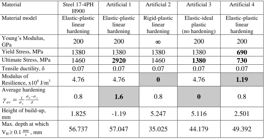
Table 1. A comparison of the influence of different material properties on deformation
response for a rigid sphere penetrating an elastic-plastic half-space.
Material Steel 17-4PH H900
Artificial 1 Artificial 2 Artificial 3 Artificial 4
Material model Elastic-plastic linear hardening Elastic-plastic linear hardening Rigid-plastic linear hardening Elastic-ideal plastic (no hardening) Elastic-plastic linear hardening Young’s Modulus,
GPa 200 200 200 200
Yield Stress, MPa 1380 1380 1380 1380 690 Ultimate Stress, MPa 1460 2920 1460 1380 730 Tensile ductility, 0.07 0.07 0.07 0.07 0.07
Modulus of
Resilience, x106 J/m3 4.76 4.76 0 4.76 1.19 Average hardening
u y
y av
1 0.8 1.6 0.8 0 0.8
Height of build-up,
mm 1.825 -1.19 5.247 5.116 2.501
Max. depth at which VH 0.1 s
mm, mm 56.737 57.047 35.025 44.179 49.392
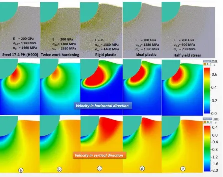
To obtain the axial expansion of the flow formed material, we are mainly interested in the
distribution field of the horizontal velocities in front of and under the penetrating object
the preform, which in turn means a more stable process and uniformity of final
microstructure formation. This study clearly shows that that the main role in providing this
belongs to the elastic properties of material, or, more particular to the modulus of resilience.
In case of the rigid plastic material (Fig 5, third column), assuming that the resilience of
material is zero, the total deformation of the material is localised around the penetrating
object, little or no deformation in the vertical direction is observed. This also shows the
necessity to simulate flow forming as an elastic-plastic problem as stated in Biba et al.,
(2015). Wider variation of the material parameters have shown that Young’s modulus and
yield stress separately don’t have much individual importance and the Modulus of Resilience
[image:14.595.77.525.356.710.2]is a sufficient parameter to reflect the role of both of them.
Fig. 5. The velocity field obtained in the simulation of the penetration of a rigid sphere into
(first row), the field of the horizontal velocity (second row), the field of vertical velocity
(third row).
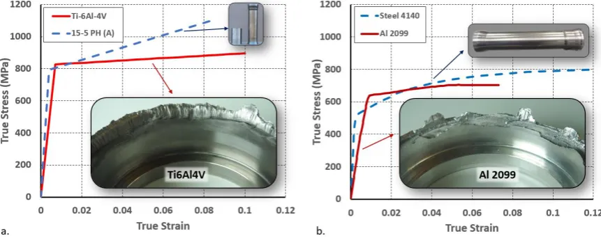
To illustrate this point with regard to the effect of yield stress, Fig. 6 presents the stress-strain
diagrams of two other materials; Al2099 and Ti6Al4V, which have a yield stress quite close
to the steels discussed above and 8–10% elongation up to fracture, yet demonstrate fracture at
an early stage of the flow forming process. It may be considered that the main reason for this
early failure is low ductility. Of course, elongation to fracture as low as 8–10% does not
simplify the process design; however, precipitate-hardening steel 15-5 PH in the “as
received” (solution treated and air cooled) condition having the stress-strain diagram shown
in Fig. 6a and a limit of only 8% tensile elongation, was nevertheless successfully flow
formed with a thickness reduction from 15 mm to 3.5 mm (about 77%). This means that, with
respect to the flow formability of these materials, the key difference between the
[image:15.595.82.513.479.650.2]elastic-plastic properties is likely to be the strain hardening level; ϒ.
Fig. 6. Stress-strain diagrams and fractured preforms of “poor” or “difficult to flow form”
materials: a) Ti6Al4V, b) Al2099.
It can be also seen from the Table 1 and Fig 5 that strain hardening does not much affect the
depth of material flow, but significantly affects to the amount of build-up (and
removes positive build up (see Fig.5 column 2). However, unfortunately it hardly explains
why high strain hardening prevents the formation of chevron cracks, which produced early
[image:16.595.75.524.154.333.2]failure of the materials shown in Fig.6.
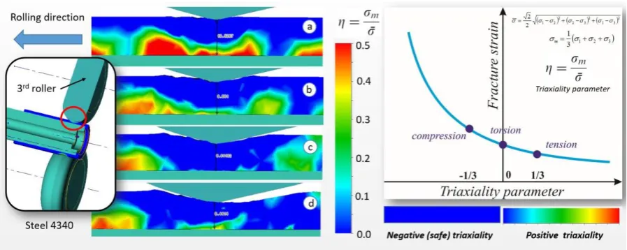
Fig. 7. A map of the positive triaxiality in the workpiece during different stages of flow
forming, i.e. thickness reduction: a) 11.5→10.5mm, b) 11.5→10.5, c) 11.5→9.9, d)
11.5→8.2. Material Steel 4340 SPH, Modulus of Resilience; 1.12 x10⁶
J/m3, the strain
hardening is shown in the Fig.10. The scale has been chosen to highlight the positive (i.e.
tensile and thus potentially dangerous) triaxiality states – all negative (compressive)
triaxiality is blue.
To understand the role of strain hardening, it is worth analysing how the flow forming
process can provide the ability to deform the material considerably beyond its tensile limit.
One of the most evident reasons, well known in metal forming, is the link between fracture
and the triaxiality state. A generic schematic of the triaxiality state in the preform during the
flow forming process obtained from FEA simulation is shown in Fig. 7. Here it should be
noted that we use the general engineering terms ‘compressive’ and ‘tensile’ with respect to
negative and positive triaxiality to reflect the general nature of the stress state. However, it is
appreciated that from a pure mechanics point of view these states are in fact more complex
than pure tension or compression. Having said this, it can be seen that the process provides
negative) directly under the roller. Fracture in this area is unlikely. Dangerous positive
(tensile) hydrostatics are significant in the initial stages of penetration (this has a low
dependence on material strain hardening). They are then gradually replaced with a safer
distribution of compressive hydrostatics providing optimal conditions for the deforming of
the materials with low ductility. At a later stage of the process positive triaxiality again
appears at the bottom of the formed part, reflecting the presence of the axial tensile force
produced by the rollers moving ahead against the material.
Hence, the spot in front of the roller is safe – there is no deformation. The location under and
slightly ahead of the roller is more vulnerable to fracture, and as can be seen in Fig. 8a,
chevron cracking can be initiated in that location (similar effects were noted in Kalpakjian et
al (1982)). However, as can be observed from Fig. 8e, the amount of accumulated plastic
deformation at this location is quite small and the axial component of the strain tensor is
much smaller than the limiting tensile elongation; about 0.04 true strain (n.b. that the loading
has a cyclic nature so the accumulated plastic deformation is higher than the equivalent
von-Mises strain). This though does not give an answer as to why the crack was initiated. The
nature of the fracture surface, shown in Fig. 8b and Fig. 8c for both Ti6Al4V and Al2099,
shows that the initial stage of fracture was almost purely brittle; ductile fracture occurring
only when the brittle crack reached the plastically deformed zone (red in Fig. 8e.). This
suggests that it was the stress that was critical for the crack initiation. In Fig. 8d, a small zone
of tensile stress (normal stress in the axial direction) can be seen. Whether this amount of
stress is sufficient to cause fracture requires further analysis (most probably it is an interplay
between crack initiation and crack development in the field of large residual stresses – the
inverse side of a large resilience). It would therefore appear when a material exhibits a high
level of strain hardening local tensile stresses can be accommodated (to some degree at least).
If the strain hardening is insufficient any stress concentrator can become critical for the
initiation of a brittle crack, which then actively develops under the large residual stresses that
Fig. 8. Chevron cracking and fracture observed during flow forming of a. & b.) Ti6Al4V, c)
Al2099; d) map of the normal component of the stress tensor in the direction of rolling, e)
map of the accumulated plastic deformation Al2099, f) typical fracture surface for this type
of failure. Note that d) and e) show deformation of only the third roller - in practice more
than one roller is used; as shown in Fig. 2b three rollers are operative with the second and
third following the first so that the level of deformation progressively increases (not shown
here).
4. Flow formability (spinnability) test
Kalpakcioglu (1964) proposed a special experimental method for assessing the flow
formability of tubes (which he termed spinnability). The purpose of this was to find the
maximum possible reduction of tube thickness per single spinning pass. The scheme of this
test is shown in Fig. 9a. The roller moves along the mandrel and penetrates into the material
at an angle, φ. The aim of the test is to find the limit after which the material breaks in
tension behind the roller. This, no doubt, is a very important test for finding the limiting
flow formability (as the author himself mentions in the discussion). As discussed by the
author and additionally proven by the damage evaluation made recently by Ma et al. (2015),
the triaxiality state at which fracture takes place in this test is very close to that of pure
tension. Besides this, the large gradient in thickness between the thinnest region and the
remaining part of the preform develops a case of localised deformation reminiscent of
necking in tension. So, it is not surprising that the forming limits obtained are in good
correlation with the maximum area reduction measured from tensile tests (though the
question of the possibility of a quantitative correlation is still not clear). However, the total
idea of flow forming and its basic approach (offering a large deformation for materials with
limited ductility) is to avoid this situation. As per the nature of the flow forming process, the
action of the tools should create in the zone of active deformation a state with dominating
hydrostatic compressive pressure (large negative values of triaxiality factor), which
significantly increases the effective fracture strain. The incremental character of the process
in its turn tends to oppose the development of strain localisation (by creating a sort of floating
neck) – the material is deformed locally in one place, then the roller moves and the next
region is deformed slightly more while the recently deformed area is somewhat unloaded. As
may be inferred from the illustration in Fig. 9a, in this spinnability test, even though it
formally remains incremental, as the “step” in front of the roller becomes bigger, the axial
pressure exerted by the roller(s) on the unformed part of workpiece transforms into tensile
force around the entire circumference of the tubular part. This is clearly visible in the results
of the modelling reported in Ma et al. (2015).
To take into account all the benefits of flow forming, and to establish the general limits of
flow formability (not per single reduction), an alternative test is proposed by the authors (see
schematic shown in Fig. 9b). This test consists of several successive passes. In each pass, the
thickness is reduced by some optimal amount (typically 20%). Each time the rollers move
along the complete length of the preform each progression being started with an axial shift
more passes to complete, but this is the cost for an attempt to have a similar level of
triaxiality at all stages of deformation.
a. b.
[image:20.595.71.509.136.339.2]c.
Fig. 9. The spinnability test a) as proposed by Kalpakcioglu (1964) and Kalpakjian and
Rajagopal (1982); b) a proposed alternative test and c) experimental results from trials carried
out by the authors (15-5 PH HT1150 steel).
In principle, these two tests may be considered to complement each other. The spinnability
test of Kalpakcioglu (1964) can be taken as a lower bound assessment, whereas that shown in
Fig. 9b would form the upper bound. This suggestion can be illustrated with the following
example. Two spinnability tests were carried out to understand the potential of 17-7PH steel
with H900 heat treatment (which significantly increases the strength but reduces the ductility
of material). The spinnability “cone” test of Kalpakcioglu produced fracture following a
thickness reduction from 15 to 8.7mm. However the “step” test allowed a final thickness of
2.9 mm to be achieved without fracture (further reduction was technically difficult with our
equipment). This outcome depends on the thickness reduction on each pass (it remains an
open question what is general spinnability). But from the practical point of view this result is
very useful, because it helps to establish the reduction strategy suitable for the particular
material. Once obtained in the “step” test a maximum reduction is stably repeatable in real
It should be noted however that although both tests can serve the purpose of assessing the
flow formability or spinnability of the material, they remain as qualitative trials rather than a
full test suitable for standardisation. Unfortunately, in both cases, the limits obtained besides
depending on the mechanical properties of the material, are also strongly influenced by the
process parameters and geometry. This is why the question of finding a correlation between
the standard elastic-plastic characteristics of a material and its flow-formability remains
important.
5. Results and Discussion
With respect to the above mentioned hypothesis, assumptions and examples, the following
summary can be drawn: the problem of the assessment of flow-formability of materials
demands -
a. the formulation of a stricter and more scientific definition of what we understand as
“flow formability” and to decide some numerical measures for grading it;
b. to find a correlation between the elastic-plastic characteristics of material behaviour
(under complex loading; typical of flow forming) and the level of its flow formability
To distinguish between common plastic ductility and flow-formability, two main aspects
have to be taken into account in defining flow-formability. The first aspect is how suitable is
a material for flow-forming – to what degree do its characteristics match the main mechanics
of this process and how wide a process window does it provide? A measure of this can be the
percentage of deviation of the process parameters about the optimal ones without the loss of
flow stability within the process, i.e. limited changes in the process control parameters (feed,
speed, depth of penetration per path, rollers’ geometry and offsets) result in continuous,
smooth and predictable changes in output characteristics (thickness reduction, surface quality,
etc.). As was discussed and illustrated in Fig. 3 and Fig. 4, the dominating physical principle
utilized for the longitudinal spread of the material is elastic resilience – the elastic energy of
un-deformed material along the mandrel. This suggests that materials with a higher level of
resilience should give more freedom in designing the process, and this can possibly be further
developed into a numerical correlation between the material resilience and level of
flow-formability.
Another elastic-plastic characteristic of the material which extends or shrinks the process
window is of course the fracture limit. However, as was shown with the example of Ti6Al4V
or Al 2099, the tensile limit (δ) is most probably not the best characteristic to estimate it. As
shown in Fig. 6a, a material with a lesser tensile elongation can exhibit superior flow
formability and even a relatively limited tensile elongation may not be a big obstacle for flow
forming. As was previously mentioned, Kalpakcioglu, (1964) reported that the tensile
reduction of area, ψ, has a better correlation with spinnability (in his definition of it). One of
his conclusions stated that “for materials with a tensile reduction of area above 45% a
maximum reduction in spinning of about 80% is the limit, irrespective of ductility. For
materials below 45%, spinnability will depend on their ductility.” This is a very valuable
conclusion, but there are two circumstances forcing us to look for some additional measures.
As was discussed in Section 4, Kalpakcioglu examined only materials with quite similar
strain hardening and in his tests assumed the limiting spinnability as correlating to the instant
when the material undergoes failure in tension behind the roller. If we are talking about
modern flow forming processes, especially spinning with several rollers, when all process
optimization is focused on the homogeneity of deformation and the minimisation of strain
localisation, then tension in the formed portion of the preform rarely appears to be the source
of damage or failure.
This draws attention to another parameter, historically related with the stability of metal flow;
strain hardening:
1 . Our forming experience shows that this parameter is very
important and maybe even is the key material characteristic for the flow forming process. It is
the thermal and stain rate sensitivity of the material is very limited, work hardening remains
almost the only available control measure against localisation of deformation and brittle
fracture. As per the classical criteria of flow localisation developed by Hart and Ghosh
(1977), the beginning of flow localisation for uniaxial tension directly depends on the
instantaneous hardening value. Assuming that strain rate sensitivity is negligible at room
temperature (i.e. m≈0) and taking the suggestion of Ghosh (1977) that deformation is
considered to be stable as long as it is accompanied by a load rise, even though imperfections
in a specimen may be growing, we get the following relationship:
0
P A A Eq. (2)
Substituting into equation (22) the following:
, and
0
ln AA
, where A and A0
are the instantaneous and initial cross-sectional area of the tensile specimen, respectively, we
obtain: 0 0 0 A A A A A A
P
A A ln ln 0 1 1
Eq. (3)
Although all these equations are derived for uniaxial tension and can hardly be directly
applied to the case of complex loading observed during flow forming, an attempt can
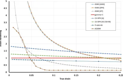
nevertheless be made to use them for initial screening. Fig. 10 shows the evolution of strain
Fig. 10. The value of the instantaneous strain hardening (ϒ) for different materials.
Two materials with low strain hardening: Ti6Al4V (with ϒ<1), and Al2099 (where ϒ drops
below 1 quite rapidly), have demonstrated cracking at the very beginning of flow forming
(see Fig. 6, Fig. 7). To establish some numerical thresholds, it is useful to analyse hardened
and tempered AISI4340, reported by Podder et al. (2012). Having quite high strain hardening
at the beginning of deformation, this material demonstrates fast degradation of hardening,
which reduces below 1 as early as 0.07 in true strain. As per the observation of Podder et al.
(2012), a preform with this heat treatment was successfully flow formed in two passes up to a
resultant 71% of thickness reduction with no defects observed. However, it should be noted
that the flow forming described in Podder et al. (2012) was of a reversed type (i.e. the
material moves in the opposite direction to the tool travel), which means that the direct tensile
load on the formed part is excluded and only bending stresses would be likely to generate
cracking. This raises an additional question, whether the flow-formability of the material is
shown in Fig. 3 will remain almost the same, while the conditions causing fracture may be
different.
While ϒ characterises instantaneous strain hardening and is different at different stages of
loading, another parameter also related with the total amount of strain hardening was used in
Kalpakcioglu, (1964): f f f d k
0Eq. (4)
Here,
f and f are the strain and stress at fracture correspondingly, for an ideal plasticmaterial, k=1, and for any hardening material k<1. The bigger the difference between yield
and ultimate stress, the smaller the value of k. As is clear from equation (4), k is relatively
independent of the value of the limiting strain and, correspondingly, on the gradients of the
true stress- true strain curve – this is the main difference between k and ϒ. As per available
experience, ϒ looks to be a more suitable parameter, reflecting both the dynamics of strain
hardening as well as the instantaneous state, although it is not yet clear how to establish a
quantitative relationship between its values and flow formability. Regarding k, some
suggestions on the dependence of maximum thickness reduction in spinning on this
parameter was suggested in Kalpakcioglu (1964) (though this is a very rough relation based
on many assumptions, simplifying the triaxiality state, neglecting friction, etc.):
k e reduction thickness
Max 1 1 Eq. (5)
This equation, however, does not look very promising. For an ideal plastic material with k=1,
the maximum thickness reduction will be 63%, and hence, any hardening material must have
at least that amount of safe reduction. At the same time, the experimental trials showed that,
for example, Al2099 having k≈0.9 failed at less than 20% of thickness reduction during flow
In summary, it may be reiterated that developing predictive measures for flow formability is a
complex issue. It involves a variety of challenges: all-component strain and stress trajectories,
changes in geometry and location of the yield surface, non-symmetrical loading and
unloading. It is simplistic to suppose that there is a chance to understand and describe the
total history of such a significantly non-uniaxial and continuously changing plastic
deformation with data generated by simple uniaxial tension. However, tensile data is almost
the only information about a material that is normally available in an industrial environment
before defining the process parameters (and before performing initial process modelling as
well). That is why it is so important to understand how to interpret this data correctly and
what set of advanced material properties is required as the next step of process optimisation.
6. Conclusions
1. It has been shown that the mechanics of plastic deformation within the flow forming
process is complex and characterised by:
a) a significantly non-uniaxial and non-uniform stress-strain state with a possibility of
high gradients of stress and strain,
b) a continuous change of the location of the zone of active plastic deformation, which
leads to the development of low cycle non-symmetric loading
c) the appearance of fracture which is dependent on a combination of factors including:
- the fast development of small defects assisted within the field of the tensile residual
stresses, which are formed as an unavoidable part of forming process,
- the triaxiality state and,
- any propensity for flow localisation should the flow become unstable
2. The complexity of the process leaves little opportunity to develop a full understanding
using only standard uniaxial tensile data. However, given that this is often the only data
forming process is offered in this paper. In addition, a new material evaluation procedure is
proposed that when used with the approach outlined by Kalpakcioglu (1964) offers a more
thorough evaluation of the flow formability of prospective alloys.
3. Three uniaxial elastic-plastic characteristics of a material seem to be the most important for
flow forming processes: resilience, strain hardening and tensile area reduction. They
influence flow-formability (or tube spinnability) of the material, although this notion itself
can be understood and numerically characterised in several different ways.
Acknowledgement:
The authors would like to offers thanks to Messier-Bugatti-Dowty & Prof. Trevor Dean for
useful inputs and the rotary processes team at the AFRC for the experimental trials.
References
AK Steel 15-5 PH stainless steel data sheet, 2007 [http://www.aksteel.com]
AK Steel 17-4 PH stainless steel data sheet, 2007 [http://www.aksteel.com]
Bennich, P., 1976. Tube spinning. Int. J. Prod. Res. 14, 11–21.
Biba, N., Vlasov, A., Stebunov, S., Maximov, A.E., 2015. An Approach to Simulation of
Flow Forming Using Elastic-Visco-Plastic Material Model, in: 13th INTERNATIONAL
COLD FORMING CONGRESS, GLASGOW.
Ghosh, A., 1977. Tensile instability and necking in materials with strain hardening and
strain-rate hardening. Acta Metall. 25, 1413–1424.
Gour M., and Tirosh J., 1982 Plastic Flow instability under compressive loading during shear
spinning Processes. J. Eng. Ind. 104, 17-22.
Kalpakcioglu, S., 1964. Maximum Reduction in Power Spinning of Tubes. J. Eng. Ind. 86,
49-51.
Kalpakjian, S., Rajagopal, S., 1982. Spinning of tubes: A review. J. Appl. Metalwork. 2, 211–
223.
Ma, H., Xu, W., Jin, B.C., Shan, D., Nutt, S.R., 2015. Damage evaluation in tube spinnability
test with ductile fracture criteria. Int. J. Mech. Sci. 100, 99–111.
Ma, Z.E., 1993. Optimal angle of attack in tube spinning. J. Mat. Proc. Tech. 37, 217–224.
Mohebbi, M.S., Akbarzadeh, A., 2010. Experimental study and FEM analysis of redundant
strains in flow forming of tubes. J. Mat. Proc. Tech. 210, 389–395.
Nagarajan, H.N., Kotrappa, H., Mallanna, C., Venkatesh, V.C., 1981. Mechanics of Flow
Forming. CIRP Ann. - Manuf. Technol. 30, 159–162.
for cyclic plasticity under nonproportional loading. Int. J. Plast. 1, 317–330.
Plewinski, A., Denger, T., 2009. Spinning and flow forming hard-to-deform metal alloys.
Arch. Civ. Mech. Eng. 9, 101–109.
Podder, B., Mondal, C., Ramesh Kumar, K., Yadav, D.R., 2012. Effect of preform heat
treatment on the flow formability and mechanical properties of AISI4340 steel. Mater.
Des. 37, 174–181.
Rajan, K.., Deshpande, P.., Narasimhan, K., 2002. Effect of heat treatment of preform on the
mechanical properties of flow formed AISI 4130 Steel Tubes—a theoretical and
experimental assessment. J. Mat. Proc. Tech. vol. 125-126, 503–511.
Roy, M.J., Klassen, R.J., Wood, J.T., 2009. Evolution of plastic strain during a flow forming
process. J. Mat. Proc. Tech. 209, 1018–1025.
Roy, M.J., Maijer, D.M., 2015. Analysis and modelling of a rotary forming process for cast
aluminum alloy A356. J. Mat. Proc Tech. 226, 118-204.
Roy, M.J., Maijer, D.M., Klassen, R.J., Wood, J.T., Schost, E., 2010. Analytical solution of
the tooling/workpiece contact interface shape during a flow forming operation, J. Mat.
Figure captions
Fig. 11. a) The details of the stress-strain curves of martensitic AK steel 15-5 PH® and 17-4 PH® with typical heat treatments “15-5 PH data sheet” (2007), “17-4 PH data sheet” (2007); b) the scheme of basic elasto-plastic parameters used for formability assessment.
Fig. 12. a) The scheme of a standard flow forming setup; b) the Flow Former used by the authors; WF STR 600-3/6.
Fig. 13. Schematic of the principles of the flow forming mechanism for materials with “good” formability (a,b,c) and “intermediate” formability (a,d,e).
Fig. 14. An example of parts flow formed (by the authors) at room temperature from “good” and “intermediate” materials. a) “good” material – HS steel, preform and final part; b) “intermediate” material – Al6082 T4, build-up of the material ahead of the roller instead of creating longitudinal extension; c) Al6082 T4, example of chip formation in front of the rollers.
Fig. 15. The velocity field obtained in the simulation of the penetration of a rigid sphere into materials with different elasto-plastic properties: general velocity vector field v xiˆ yjˆ
(first row), the field of the horizontal velocity (second row), the field of vertical velocity (third row).
Fig. 16. Stress-strain diagrams and fractured preforms of “poor” or “difficult to flow form” materials: a) Ti6Al4V, b) Al2099.
Fig. 17. A map of the positive triaxiality in the workpiece during different stages of flow forming, i.e. thickness reduction: a) 11.5→10.5mm, b) 11.5→10.5, c) 11.5→9.9, d) 11.5→8.2. Material Steel 4340 SPH, Modulus of Resilience; 1.12 x10⁶
J/m3, the strain hardening is shown in the Fig.10. The scale has been chosen to highlight the positive (i.e. tensile and thus potentially dangerous) triaxiality states – all negative (compressive) triaxiality is blue.
Fig. 18. Chevron cracking and fracture observed during flow forming of a. & b.) Ti6Al4V, c) Al2099; d) map of the normal component of the stress tensor in the direction of rolling, e) map of the accumulated plastic deformation Al2099, f) typical fracture surface for this type of failure. Note that d) and e) show deformation of only the third roller - in practice more than one roller is used; as shown in Fig. 2b three rollers are operative with the second and third following the first so that the level of deformation progressively increases (not shown here).
Fig. 19. The spinnability test a) as proposed by Kalpakcioglu (1964) and Kalpakjian and Rajagopal (1982); b) a proposed alternative test and c) experimental results from trials carried out by the authors (15-5 PH HT1150 steel).
Fig. 20. The value of the instantaneous strain hardening (ϒ) for different materials.
Table caption