City, University of London Institutional Repository
Citation
:
Iezzi, M. and Read, M. G. ORCID: 0000-0002-7753-2457 (2017). Enabling solid
biomass fired small scale cogeneration systems with the twin screw wet steam expander
technology. In: European Biomass Conference and Exhibition Online Proceedings 2017.
European Biomass Conference and Exhibition Proceedings, 2017 (25thEU). (pp.
1938-1944). Florence: ETA-Florence Renewable Energies. ISBN 978-88-89407-17-2
This is the accepted version of the paper.
This version of the publication may differ from the final published
version.
Permanent repository link: http://openaccess.city.ac.uk/20032/
Link to published version
:
http://dx.doi.org/10.5071/25thEUBCE2017-ICO.12.2
Copyright and reuse:
City Research Online aims to make research
outputs of City, University of London available to a wider audience.
Copyright and Moral Rights remain with the author(s) and/or copyright
holders. URLs from City Research Online may be freely distributed and
linked to.
City Research Online:
http://openaccess.city.ac.uk/
[email protected]
ENABLING SOLID BIOMASS FIRED SMALL SCALE COGENERATION SYSTEMS WITH THE TWIN SCREW WET STEAM EXPANDER TECHNOLOGY
Dr M. Iezzi 1, Dr M.G. Read2
1 Heliex Power Ltd, Bramah Avenue, East Kilbride, Glasgow, G750RD, UK 2 City, University of London, Northampton Square, Clerkenwell, London EC1V0HB, UK
ABSTRACT: Distributed power generation in industrial, urban and commercial applications is a key topic for the strategic development and implementation of modern energy policies. Solid biomass fired small scale cogeneration plants can play an important role in Europe to improve environmental and economic impact of such policies. As a result of advances in the design and development of twin-screw wet steam expanders, they now appear as an efficient enabling technology for this small scale de-centralized cogeneration plants. Same as backpressure turbines, twin-screw steam expander can generate power by reducing the pressure between the steam source and the downstream steam/heat user, but with the advantage of adopting wet steam as working fluid. The paper will describe the principles of steam screw expander operation and performance characterization and discuss installations of the expander genset in various industrial and urban (district heating) applications where steam is generated with solid biomass fired saturated steam boilers.
KEYWORDS: combined heat and power generation (CHP), distributed generation, steam, steam engine, district heating, solid biofuel.
1 TWIN SCREW EXPANDER TECHNOLOGY
Positive displacement machines have a wide range of application, particularly in the fields of refrigeration and compressed air production, and their total world production rate is in excess of 200 million units per annum. One of the most successful positive displacement machines currently in use is the screw compressor, and there is increasing interest in the applications of these machines as expanders. The use of twin screw expanders in place of turbines offers a number of potential advantages for some applications, as they can be manufactured relatively cheaply and can be considered for wet vapour expansion applications unsuitable for traditional turbines. This section describes the basic operation of twin screw expanders before briefly discussing methods of analysing and model expander performance.
1.1 Main components and working principle
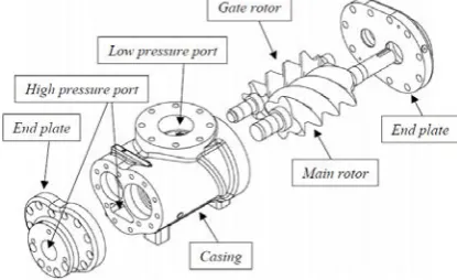
[image:2.595.344.486.422.663.2]The main components of a twin screw positive displacement machine are shown in Figure 1. Its principle of operation is based on volumetric changes in three dimensions rather than two. As shown, it consists of a pair of meshing helical lobed rotors, contained in a casing. The flutes formed between the lobes on each rotor form a series of working chambers in which vapour or two-phase fluid is contained.
Figure 1: Exploded diagram of the main components of a twin screw machine
Details of the operation of a screw expander are illustrated in Figure 2. Beginning at the top and back of the rotors, there is a starting point for each chamber where the trapped volume is initially zero. As rotation proceeds in the direction of the arrows, the volume of that chamber increases as the line of contact between the rotor with convex lobes, known as the main rotor, and the adjacent lobe of the gate rotor advances along the axis of the rotors towards the front.
High pressure (suction) port closes
Low pressure (discharge) port opens
Figure 2: Illustration of working chamber volume change in screw expander operation
[image:2.595.70.278.612.739.2]form along virtually the entire length of the rotor, shown in the light shaded portion of Figure 2. At this position, the low pressure port starts to be exposed to the working chamber, allowing discharge to begin. Further rotation then leads the trapped volume starts to decrease. On completion of a further 360º of rotation by the main rotor, the trapped volume returns to zero.
For a specified geometry, the characteristics of the twin-screw machine such as the curve of working chamber volume against angular position (illustrated in Figure 3), sealing line lengths, blowhole area and axial/radial clearances between the rotors and the casing all influence expander performance. Incorrect selection of machine parameters can lead to over or under expansion of the working fluid. The correct values for a particular application depend on a range of factors, and optimization is possible using the expander modelling software.
Figure 3: Illustration of volume change in screw expander operation and the effect of the suction port on the built-in volume ratio.
1.2Steam expander performance modelling
The main aspects of a detailed computational model for screw machines were established by Taniguchi et al. [1988], and developments in numerical methods have allowed the investigation of rotor profiles and machine geometries for a range of applications [Tang and Fleming, 1992, Fleming et al., 1995, Fujiwara and Osada, 1995]. The full thermodynamic model of the expander used to investigate the performance of screw machines in the current study is based on the quasi one-dimensional analysis of twin-screw machines as described by Stosic and Hanjalic [1997], which has been extensively validated for compressors for a wide range of working fluids and operating conditions. For expanders, the model has been validated for expansion of low dryness fluid (including saturated liquid) using several refrigerants [Smith et al., 1996]. Using this procedure, machine geometry and rotor profiles have been optimised for a particular set of operating conditions representative of those considered in this paper, and have been fixed for the purposes of the current study. The ‘N’ rotor profile developed at City University has been used, as this geometry is known to have benefits including greater throughput and a stiffer gate rotor than is possible using alternative profiles with similar blow-hole area and sealing line lengths [Smith et al., 2014].
1.3Testing and model validation
Experimental testing of screw machines optimised for wet steam expansion has been performed [Read et al., 2014], and examples of the data obtained is shown in Figure 5. These results have been compared to the results
from the computation expander model, and good agreement has been shown between the measured and predicted expander performance.
The performance of the screw expander demonstrates the suitability of these machines for generating power from the expansion of wet steam. The validated expander model provides an essential tool to characterise the requirements and performance of wet steam biomass fired Combined Heat and Power (CHP) systems and pressure reduction applications, which are described in the following sections.
Figure 4: Comparison between predicted and measured shaft power output and mass flow rate
2 APPLICATIONS OF THE TWIN SCREW STEAM EXPANDER
Same as backpressure turbines, twin screw steam expander can generate power by reducing the pressure between the steam source and the downstream steam/heat user, but with the advantage of adopting wet steam as working fluid. Such “low grade steam” is traditionally produced for heating purposes, not for power generation where standard turbines require superheated steam. The twin screw steam expander can use wet steam thanks to low tip speeds of the rotors, robust design and special rotor profile, introducing the opportunity of power generation in several applications where it was not possible or not economically viable in the past.
2.1 Exploiting steam pressure drops
[image:3.595.322.518.220.518.2] [image:3.595.73.277.290.399.2]bar, and transport it to locations in the plant where it is required for processes. At the point of use, the steam pressure is reduced to the required value, suitable for the process. Since raising steam at these higher pressures has little effect on either the fuel consumption or the boiler cost, the total plant cost is reduced because the associated higher density steam can be transmitted in smaller diameter pipes. The opportunity therefore exists to replace the local PRVs (Pressure Reduction Valves) by expanders as shown in Figure 5, and thereby recover power from the expansion process. The shaft power produced can be used to drive a generator and produce electricity thereby reducing the site electricity consumption. Alternatively, it can be used to drive a mechanical load such as an air compressor, eliminating the need for electrical equipment and the associated losses.
Figure 5: Illustration of screw expander for PRV application in a steam distribution system.
It is important to appreciate that, when the steam is required for a heating process, any power extracted from the steam - and converted into mechanical power - must be compensated by the combustion of additional fuel in the boiler to increase the steam production rate so that the steam leaving the expander has the same energy, as that leaving the PRV, from which no energy is extracted. It should be noted that the efficiency of the process of conversion of heat to electricity, by this means, is approximately equal to the conversion efficiency of the mechanical power output from the expander to the electricity supplied to the grid, which approaches 90%, and is independent of the adiabatic efficiency of the expander itself. This is because the additional fuel burned only has to supply energy equal to the mechanical power extracted. Hence a low efficiency expander will produce less power but will require less additional fuel to be burned to supply the required process heat. Nonetheless, a high expander efficiency for any given type of machine is desirable because more power will therefore be produced for roughly the same size unit and hence the capital cost per unit output will be minimised.
The economics of this process then depend on the relative difference between the cost of electricity obtained from the utility and that of the fuel being burned. Typically, the cost per kilowatt-hour of electricity supplied by the grid is 3 – 4 times the cost per
kilowatt-hour of heat derived from the burning of natural gas. Electricity generated by this means is, therefore not obtained for zero fuel cost but for some-where in the region of one third that of electricity supplied by the utility. Moreover, several applications, including biomass fired plants, may benefit of incentives which sums positively to the installation economics.
Screw expanders have some distinct advantages for such applications, which are generally for power outputs of only a few hundred kilowatts, namely:
• They tend to be cheaper than turbines of equivalent power output.
• They have similar adiabatic efficiencies.
• Unlike turbines, they can admit wet steam without loss in efficiency or reduction in service life.
• They can handle large flow variations without
affecting the adiabatic efficiency significantly.
2.2 Power generation in biomass plant
In case of small-scale biomass fired boilers (generally below 10MWth), generating saturated or wet steam is much easier and economically viable than superheated steam. In fact, the boiler can handle more flexibly the variation of the fuel quality (e.g. moisture content or, in general terms, calorific value) operating within the steam saturation curve where variation of heat input may easily transfer to little modification of the steam dryness fraction rather than changes in superheated steam temperature. This offers a good opportunity for revamping/upgrading existing hot water boilers with simple water tube wet steam generators, allowing a proficient move from simple heating plants to CHP systems. Moreover, such a flexible cycle allows a simple and cost-effective power generation system with “difficult” fuels like chicken manure, where the calorific value is highly variable over time and the emission quality is a priority parameter for the combustion regulation.
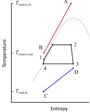
Figure 6: Schematic illustration of heat recovery from heat source (A-B) using simple wet steam cycle.
[image:4.595.74.268.283.457.2] [image:4.595.343.498.498.691.2]benefit of this cycle is that is allows a compromise to be achieved between high mean temperature of heat addition and high recovery of heat from source fluid.
In order to prevent high volume flow rates and achieve good expander efficiency, the heat rejection for the cycle should occur between 100°C and 140°C, which has several advantages for CHP applications:
• High “quality” (steam) and reasonable temperature heat is available to feed the downstream process.
• In case of excess heat after the expander (power
driven applications) the high log mean temperature difference in the condenser means that the required heat exchange area is small and the fan power requirement for an air-cooled system is very low.
• Condensing at or above atmospheric pressure
prevents corrosion issues due to air ingress.
• Cheap installation cost (no superheated steam on the hot side, no sub-atmospheric pressure on the cold side).
The clear drawback is that the relatively high temperature of heat rejection reduces the cycle efficiency in accordance with Carnot’s principle. However, in CHP applications the condensing steam is always used as a heat source, either for local heating applications, of for hot water heat exchangers, so the overall system efficiency (combined heat and power output over thermal power input) is always sensibly high.
However, where higher cycle efficiency is required, a first possibility is to use a double stage expander configuration, where a smaller high-pressure expander releases intermediate pressure steam to a larger low-pressure stage expansion unit. This configuration offers a simple and cheap opportunity to increase the cycle efficiency up to 12-14%, with the temperature of the rejected heat still relatively high (100-110°C ).
Another possibility for increasing the cycle efficiency is to condense the low-pressure steam rejected by the expander in the evaporator of a low temperature bottoming Organic Rankine Cycle as shown in Figure 7.
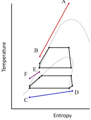
Figure 7: Schematic illustration of heat recovery from heat source (A-B) using a cascaded wet steam cycle/saturated vapour ORC, where the lower operating temperature of the ORC allows the jacket water heat source (E-F) to be utilized in case of WHR on biogas piston engines.
This configuration, even if characterized by higher technical complexity, allows significantly higher electrical efficiency (up to 16-18% even for small power ranges below 500kWe), but is limited to applications (like greenhouses), where heat is required at relatively low temperature (30 to 60°C). The combined wet steam and low temperature ORC system can be used also in other waste heat recovery applications, including biogas engines where heat recovery is not limited to the high temperature combustion exhaust gases, but can be extended to the lower temperature water in the engine cooling jacket as represented in figure 7.
3 DEVELOPMENT OF THE TWIN SCREW
EXPANDER GENERATOR SET
3.1 Main components and technical features
An example of a screw expander generator set
developed for biomass and pressure reduction
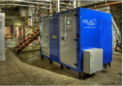
[image:5.595.318.518.415.591.2]applications is given in Figure 8. As shown, the unit is totally enclosed and contains, within it, the expander coupled directly to the electrical generator. It only requires connection to the steam supply and to the electricity mains. Start up and shut down are fully automated and, in the event of the system failure, the steam supply to the expander is cut off and a parallel (bypass) PRV is activated automatically, thus making the entire process fail safe.
Figure 8: Illustration of a process steam screw expander genset (by courtesy of Heliex Power Ltd).
The bare expander has the following main components:
• Main housing: is the rotors housing where the steam expansion occurs. It has the inlet and outlet ports cast in order to define the correct BIVR and has the flanged connections to the inlet and outlet steam pipes. The component is made in spheroidal graphite cast iron.
• Bearings carrier: together with the housing it creates the closed steam chamber into the machine. It also carries the bearings at the low-pressure side, where the drive shaft exits. The component is made in spheroidal graphite cast iron.
[image:5.595.102.254.509.710.2]increasing volume in order to make the expansion. The rotors are made in carbon steel with special surface treatments to improve the self-lubricating properties and resistance to corrosion.
• Seals: have the main function of keeping the steam into the steam chamber and the bearings lube oil into the bearings housing, avoiding any reciprocal contamination. The vented steam is recovered by connecting the vents to the low-pressure pipe. • Bearings: carry the axial and radial load of the rotors
under the steam pressure and provide the proper positioning of the rotors. They are conventional oil lubricated roller bearings with some special features to withstand high working temperature.
• Lubrication system: provides oil to the bearings via an air blast heat exchanger.
Figure 9: Cut view of a twin screw steam expander assembly (by courtesy of Heliex Power Ltd).
In addition to the steam expander, generator set package includes the following:
• Electrical generator
• Mechanical power transmission from the expander to the electrical generator
• Inlet steam control valve
• Reverse flow safety bypass and check valve
• Electrical control panel, including controller and sensors
• Base frame, canopy and internal ventilation system The mechanical power produced by the expander is used to drive an asynchronous generator via a belt drive transmission. The expander rotational speed may be higher than the generator synchronous speed (3000 rpm, 2 pole) and the speed ratio is set by the pulley ratio. The expander runs at constant speed and there is no need for a mechanical variable speed system nor electrical inverter. To manage variable mass flow rates, a control valve at the expander inlet modifies the steam pressure and, consequently, the inlet steam density. The machine thus delivers the same volumetric flow, but different mass flows (the higher the inlet pressure, the higher the density, the higher the mass flow and vice versa).
When the expander works as replacement of pressure reduction valve (PRV), the control system ensures that the steam pressure downstream of the expander is maintained within customer-specified limits. A pressure transducer located on the outlet pipe provides the control signal for the inlet valve to ensure the specified outlet pressure is maintained. Usually, when working as PRV, the customer’s existing pressure control valve is left in place and may be used for both back-up purposes and to
manage fluctuations of steam demand so that, with careful selection, the expander working hours are maximised and the machine works as much long as possible at maximum load.
The overall management of the machine is made by a fully automated control system, which may be a proprietary system. The generator set control system may be updated and adjusted to suit the customer’s requirements or any other specification. Using an asynchronous generator, the speed control is given by the grid frequency, so the machine needs to be connected to a grid to function properly. “Island” installations may be possible using finer control system and synchronous generator plus inverter.
During start-up the expander drives the generator up to synchronous speed at which point the circuit breaker closes and the system starts to generate electrical power. This minimises the inrush current. The shut-down procedure involves simply closing the inlet control valve. When the steam ceases to enter the machine, the expander stops rotating and the generator is isolated from the grid so that it doesn’t absorb current. Emergency stop is achieved via manual stop buttons on-board the generator set and automatically via several monitored parameters.
Adiabatic efficiency of installed machines ranges from 55% to 75% based on the match between the nominal steam volume ratio and the built-in volume ratio. Overall electrical efficiency (electrical power/inlet steam power) ranges from 7 to 10% (single stage expander) based on the operating conditions (mainly the outlet pressure).
It should be noted that performance for specific applications depends on a wide range of factors including the inlet pressure, pressure drop, mass flow rate, and the rotational speed and built-in volume ratio of the expander. Detailed analysis is therefore essential in order to predict the power available in a particular application.
4 EXAMPLES OF INDUSTRIAL APPLICATIONS
Current twin screw steam expander technology has been demonstrated in a wide range of applications. Screw expander systems using screws with 145 and 204mm diameter main rotors are commercially available and some of them are currently operating at industrial sites. Thanks to the already mentioned technical suitability and supported incentives promoted by local governments, many of these installations are on biomass fired boiler applications.
4.1 Biomass CHP in district heating networks
[image:6.595.73.277.270.420.2]scheme. In this instance, the client is not applying for the Solid Biomass CHP systems tariff under the Renewable Heat Incentive (RHI) scheme for heat generated from a renewable source because their biomass boiler was commissioned prior to December 2013.
Figure 10: 106kWe steam expander genset installed in a biomass CHP application (by courtesy of Heliex Power Ltd).
In other recent UK projects, the system would be eligible for the Solid Biomass CHP Systems tariff, guaranteed for 20 years, in many cases offering a return on investment for the screw expander system of under one year. Similar configuration of the twin screw steam expander for CHP in district heating schemes were successfully implemented also Austria and in Italy, where incentives schemes are also in place.
4.2 Small biomass CHP serving the local hospital Hospitals may require steam for several purposes, from hating to sterilization, cooking, ironing cleaning atc. Where biomass is locally available, small biomass boilers (generally backed up by fossil fuel boilers) in combination with the steam expander generator offer a good solution for small scale decentralized combined heat and power generation. An example can be found in Scotland where a small 80kWe steam expander generator set is generating power after a wood chips steam boiler.
4.3 Small scale biomass CHP for chicken farms and nurseries
Chicken farms use heat to grow the chickens in the sheds. They also dispone of significant amount of chicken manure, which can be treated as fuel for special biomass boilers. Due to the difficulties of efficiently burning chicken manure, the opportunity to raise wet steam instead of superheated steam is very appealing under both technical and economics point of view. A few wet steam expander generator sets are operating in the UK in chicken farms.
Nurseries also require heat and are another typical farming application where the wet steam cycle was applied in UK
4.4 Wet steam expander for the wood and timber industry Drying is a critical process in wood industry which is typically performed using steam as thermal vector. At the same time, such industries release significant amount of biomass waste that can be used in biomass boilers to raise steam and run the wet steam expander in CHP configuration. Incentives and “free fuel” play a good role
in several countries (including East Europe and Nord America) for incentivizing decentralized generation of both heat and power. The steam expander was adopted in a couple of sites in Europe (UK and Italy).
5 CONCLUSIONS
Screw expanders have now been developed to the stage where they are available for commercial installations to generate power from low grade steam. Such machines are particularly valuable as replacements to pressure reduction valves in industrial steam applications as well as in small scale biomass plants serving district heating networks, farms, civil utilities and industrial plants where operational flexibility, robustness and appealing economics are key factors.
The steam screw expander technology matches very well with the increasing requirement of decentralised combined heat and power generation, as well as with the growing requirement of generating more and more green power from renewable sources.
6 REFERENCES
[1] Fleming, J. S.; Tang, Y.; Xing, Z. W.; Cook, G., 1995, The Use of Superfeed in a Refrigeration Plant With a Twin Screw Compressor: an Optimization Technique for Plant Design. In Proceedings of the IIR XIXth Congress on Refrigeration, The Hague [2] Fujiwara, M.; Osada, Y., 1995, Performance analysis
of an oil-injected screw compressor and its application. International Journal of Refrigeration, 18, (4), 220-227
[3] Hanjalic, K., Stosic, N., 1997, Development and Optimization of Screw Machines with a Simulation Model - Part II: Thermodynamic Performance Simulation and Design Optimization, Journal of Fluids Engineering, 119(3): 664-670.
[4] Read, M.G., Stosic, N., & Smith, I. K., 2014, Optimization of Screw Expanders for Power Recovery From Low-Grade Heat Sources, Energy Technology & Policy, 1(1), 131-142.
[5] Smith, I.K., Stosic, N., Aldis, C.A., 1996, Development of the Trilateral Flash Cycle System: Part 3: The Design of High-Efficiency Two-Phase Screw Expanders, Proceedings of the Institution of Mechanical Engineers, Part A: Journal of Power and Energy, 210(1): 75-93.
[6] Smith, I.K., Stosic, N., Kovacevic, A., 2014, Power Recovery from Low Grade Heat by Means of Screw Expanders, Elsevier.
[7] Tang, Y.; Fleming, J. S., 1992, Obtaining the optimum geometrical parameters of a refrigeration helical screw compressor. In 11th International Compressor Engineering Conference, Purdue University, pp 221-227.
7 ACKNOWLEDGEMENTS