Abstract—This work introduces a novel Leaky Least Logarithmic Absolute Difference (LLLAD) based control algorithm and Learning based Incremental Conductance (LIC) MPPT (Maximum Power Point Tracking) algorithm, for grid-integrated solar PV (Photovoltaic) system. Here, a three-phase topology of grid-integrated PV system is implemented, with the nonlinear/linear loads. Proposed LIC technique is an improved form of an Incremental Conductance (InC) algorithm, where inherent problems of traditional InC technique like steady-state oscillations, slow dynamic responses and fixed step size issues, are successfully mitigated. The prime objective of proposed LLLAD control is to meet the active power requirement of the loads from generated solar PV power, and after satisfying the load demand, the excess power is supplied to the grid. However, when generated solar power is less than the load demand, then LLLAD meets the load by taking extra required power from the grid. During these power management processes, on the grid side, the power quality is maintained. During daytime, the proposed control technique provides load balancing, power factor correction, and harmonics filtering. Moreover, when solar irradiation is zero, then the DC link capacitor and VSC, act as DSTATCOM (Distribution Static Compensator), which enhances the utilization factor of the system. The proposed techniques are modeled, and their performances are verified experimentally on a developed prototype, in solar insolation variation conditions, unbalanced loading, as well as in different grid disturbances such as over and under-voltage, phase imbalance, harmonics distortion in the grid voltage etc. Test results have met the objectives of proposed work and parameters are under the permissible limit, according to the IEEE-519 standard.
Index Terms—Solar PV Array, Power Quality, Grid Integrated System, InC, MPPT.
I. INTRODUCTION
OWER generation and distribution systems are undergoing substantial changes, because of modern technology and new advents, such as integration of large-scale renewable distributed generations, advanced communication and control schemes, and large storage capability. Out of several renewable resources, due to the static structure, small size and almost zero maintenance cost, solar PV (Photovoltaic) based energy generating system is highly popular [1]. The available literature reveals that out of several ways of grid integration of solar PV system, a two-stage topology is the most popular way of synchronization, where two converters are used. One DC-DC converter is used for maximum power point tracking (MPPT), and another DC-AC converter is used for power conversion as well as grid synchronization. Two-stage topology is popular, because, here DC link voltage and PV voltage are different, so a two-stage system can work with any rating of the PV array. In case of high PV voltage fluctuation condition, a two-stage
system is the only option for operating in constant DC link voltage condition. Moreover, due to two separate controls for the DC converter (such as a boost converter) and the DC-AC converter such as for VSC (Voltage Source Converter), the overall control complexity is very less [2][3].
However, for optimal operation of DC-AC converter (VSC), an efficient control technique is needed. The prime objective of the control technique is that the generated solar power is supplied to the nearby loads and, after satisfying the load demand the rest power is supplied to the grid. However, when generated solar power is not sufficient for the load, then the load requirement is met by taking extra required power from the grid. In this process, the responsibilities of the control technique, are, (1) power conversion from DC to AC, (2) to follow the grid code for synchronization with the grid, (3) power quality improvement of the supply power, (4) to act as DSTATCOM (Distribution Static Compensator), when solar irradiation low, and (5) power management. It provides power factor correction, harmonics filtering and mitigation of other power quality issues.
In-depth literature review on ‘control techniques for the grid integrated solar PV system’ depicts that recently, researchers have proposed several adaptive control algorithms [4], such as fuzzy adaptive control [5], learning based control [6], power delta control etc. However, for abnormal grid conditions, the performances of these control techniques, are not reported, which is the essential phenomenon of the distribution grid. The other control techniques like, discrete-Fourier transform (DFT), PM (Prony’s method), frequency locked loop (FLL) [7], second-order generalized integrator (SOGI) [8] and Kalman filter (KF) [9] have been proposed to handle the abnormal grid condition. However, none of these techniques, is suitable for all types of grid adverse conditions, such as FLL and SOGI based control techniques are unable to handle lower order harmonics and DC offset [10]. The fixed length window with stationary waveform is required for searching in DFT based control technique, which is not suitable for online searching. The performance of PM is appreciable in different grid adverse conditions. However, in the PM technique, the higher order polynomial equation and its solution process, create a huge computational burden on the processor, which is not suitable for the low-cost microcontroller. Similarly, KF based control technique is good for solution estimation using correction and prediction process. Moreover, the modified version of KF, like extended KF [11] and linear KF [12] based control techniques are also good for the integrated grid system. However, during state variable estimation, linearization, prediction and correction, the derivative properties are used, which is the
Leaky Least Logarithmic Absolute Difference Based
Control Algorithm and Learning Based InC MPPT
Technique for Grid Integrated PV System
Nishant Kumar,
Member IEEE,
Bhim Singh,
Fellow IEEE,
Bijaya Ketan Panigrahi,
Senior Member IEEE
,
and L. Xu,
Senior Member, IEEE
source of burden and the algorithm complexity on the processor. Therefore, a heavy computational burden arises on the processor, which is not suitable for a low-cost microcontroller. Model predictive control technique [13] is also popular for good steady-state response, but during dynamic condition, its responses are poor, due to its predictive nature, which is based on the previous dataset. Similarly, resonant controllers, for tracking the sinusoidal inverter current, in grid connected system has been presented in [14], which shows a good steady state response with low harmonics content in injected grid current. However, during transient condition, the performance rapidly deteriorates, due to the changes in the grid frequency.
Therefore, in this paper, a novel Leaky Least Logarithmic Absolute Difference (LLLAD) based control algorithm is proposed for efficient and robust operation of grid-integrated solar PV system. This technique is free from the derivative term, so the computational burden is low, as well as the performance of LLLAD control is instantaneous and suitable for the high-frequency system.
Moreover, in this paper, a Learning-based Incremental Conductance (LIC) based Maximum Power Point Tracking (MPPT) algorithm is proposed. This LIC is the improved form of Incremental Conductance (InC) algorithm, which mitigates the inherent problems of traditional InC algorithm [15], like steady-state oscillation, slow dynamic responses and fixed step size issues. A literature review on MPPT shows that many authors have tried to solve these problems through some modifications in classical algorithms namely, modified perturb and observed (P&O) [16], improved InC [17], fuzzy logic based MPPT[18], artificial intelligence based MPPT approach [19], etc. However, still, an optimum solution has not come. Because, if few improved techniques are performing well in the steady state then these are lagging during dynamics, vice versa. Moreover, few techniques are performing relatively well, but the huge computational complexity and large design constraints, restrict to perform on the low-cost processor. Therefore, LIC algorithm is proposed, which simple structure is easy in implementation and its learning nature decides the size of step change according to the situation, such as step size decreases during steady state condition, and step size increases during dynamic changes.
In this work, the merits of LLLAD control algorithm and LIC MPPT technique are verified experimentally on a developed prototype in solar irradiation variation conditions, imbalanced condition of linear/nonlinear loads, as well as in different grid disturbances such as voltage unbalances, phase imbalances, harmonics distortion in grid voltage etc. Test results and analysis show a very good and optimal power management. However, the drawback is, high algorithm complexity of the proposed control technique w.r.t. state of the art techniques. Therefore, for easy implementation and to reduce the algorithm complexity, the block diagram of LLLAD for the active component extraction has been given and described in section II(B).
II. SYSTEM LAYOUT
A two-stage topology of three-phase grid-tied solar PV system is given in Fig.1, where solar PV power is supplied to the grid, through a DC-DC converter and a three-phase voltage source converter (VSC) in such a way that the operating point of PV
array is at MPP (Maximum Power Point) and, the converter power is synchronized to the grid. Here for control, LIC MPPT algorithm is used for the DC-DC converter, and LLLAD based control algorithm is used for the DC-AC VSC. In this configuration, at the point of common coupling (PCC), ripple filter (Cr, Rr), grid through interfacing inductor (LVSC, RVSC),
load and output terminal of VSC are connected. Here, the ripple filter is used for absorbing switching ripples, which are produced by VSC. The main objectives of control scheme, are during PV power generation, the power is fed to the grid in UPF (Unity Power Factor) mode of operation, and when PV power is unavailable then it operates in DSTATCOM (Distribution Static Compensator) mode.
LVSC,
RVSC
CDC
+
_
S1 S3
S4
S2
iVSCa iVSCb
iVSCc Zsa
iga
vsab
vsbc
S6
S5
vMa
Distribution System Equivalent
Interfacing Inductors Three Phase VSC
VSC Control (LLLAD)
S4
S3
S1 S2 i ga, igb, igc
vsa, vsb, vsc
VDC S6
S5
Zsb igb
vMb
Zsc igc
vMc
Rr Cr Ripple Filter
Load
PCC
DC Link Capacitor
AC Tie Line
}
+ _
}
DC Tie Line
+
_
iPV
S7
Boost Converter
vPV Solar PV array
MPPT (LIC) ipv
vpv
VDC
iLa iLb iLc
Fig.1 Three-Phase Grid-tied Solar Energy Conversion System.
III. CONTROL APPROACH
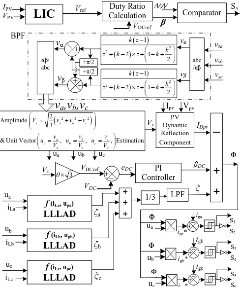
In the proposed control scheme, two separate control strategies are used for the boost converter and for VSC, which is shown in Fig.2. For boost converter, a novel LIC MPPT technique is used for maximum power harvesting from the solar PV array. Moreover, for VSC, a novel LLLAD based control strategy is used for UPF operation. Here, LLLAD algorithm is used for extraction of fundamental component from load current and estimation of grid reference currents.
First, LIC MPPT technique is used for the boost converter, which produces a reference voltage (Vref), for operating on
maximum power.
For keeping constant DC link voltage (VDCref) and to operate
at Vref, an optimal duty cycle (β) is calculated, which is
described as,
1 ref
DCref
V V
(1)
For generating switching signal for the boost converter (S7),
the sawtooth signal and calculated β are compared, which generates switching pulse. VDCref is calculated [20] as,
3
DCref x
V V (2)
Where, Vx is amplitude of the grid voltage, and θ is loss
compensation component.
After this, by using a bandpass filter, the fundamental components of PCC voltages (va, vb, vc) are extracted from the
grid line voltages (vsa, vsb, vsc). These va vb, and vc are in-phase
quantities of vsa, vsb, and vsc. The transfer function of the
22 1 2 1 2 f k z T k z k z k
(3)
Where, k=√2×ω×Ts, Ts and ω are sampling period and natural
frequency (2πf), respectively.
ua PV Dynamic Reflection Component ξ IDpv Vx PI Controller VDC VDCref +_ Vpv
f (iLa, upa) LLLAD
eDC βDC
ub uc
+ + + iLa
ua
f (iLb, upb) LLLAD iLb
ub
f (iLc, upc) LLLAD iLc uc 1/3 LPF Φ ξa ξb ξc
iga*
S1 S2
+
+
+
_
igb*
S3
S4
igb
igc*
S5
S6
igc
LIC
IPV
VPV Comparator
β S5 Duty Ratio Calculation Vref VDCref 3 Vx abc /αβ αβ/ abc vsa vsb vsc vα vβ
v
a,v
b,v
ciga Φ ua Φ ub Φ uc
2
2 1 2 1 2 k z k
z k z k
2
2 1 2 1 2 k z k
z k z k
+ _ + + +π/2 +π/2 vα vβ Ipv BPF
2 2 2 2
Amplitude 3
& Unit Vector , , , Estimation
x a b c
a b c
a b c
x x x
V v v v
v v v
u u u
V V V
[image:3.612.47.292.118.409.2]
Fig.2 Control scheme for grid-integrated solar power generation system. For improving the dynamic performances, by using the solar PV dynamic reflection component (IDpv), the impact of the
instantaneous reflection in PV power (PPV) on the grid current
is taken under consideration, which is derived as,
2 3 pv pv Dpv x V I I V
(4)
For maintaining the DC link voltage, VDCref is compared with
the sensed DC link voltage (VDC), which generates DC link
voltage error (eDC= VDCref - VDC). This eDC is fed to the PI
(Proportional Integral) controller, which gives the value of the DC loss component (βDC), as,
0
(n 1) G (n) (n)
t
DC P DC I DC
n
e G e
(5) Where, GP and GI are proportional and integral gains of the PIcontroller, which regulates DC link voltage.
For estimating active weight components (ξa, ξb, ξc), three
separate LLLAD control blocks are used, which are the function of load currents (iLa, iLb, iLc), in-phase unit-templates
(ua, ub, uc).
LLLAD
LLLAD
LLLAD
(i , u ) (i , u ) (i , u )
a La a
b Lb b
c Lc c
f f f (6)
The resultant estimated active weight component (ξ) and resultant active weight component (Φ) are calculated as,
1
3 a b c
(7)
DC
I
Dpv
(8) The reference grid currents (iga*, igb*, igc*) are generated as,* * *
, ,
ga a gb b gc c
i u i u i u (9)
The switching pulses (S1, S2, S3, S4, S5, and S6) of voltage
source converter are generated by using hysteresis controller [21], where the input signals are grid currents (iga, igb, igc) and iga*, igb*, igc*.
A. Learning-Based Incremental Conductance (LIC) Algorithm
The efficiency of the solar PV array is improved by using a MPPT algorithm, which forces it to operate at the maximum power point. The most popular MPPT techniques are P&O, and Inc. However, the problems with these techniques are steady-state oscillations, slow dynamic response and fixed step size issues. Therefore, for mitigating all above problems, a novel LIC algorithm is proposed here.
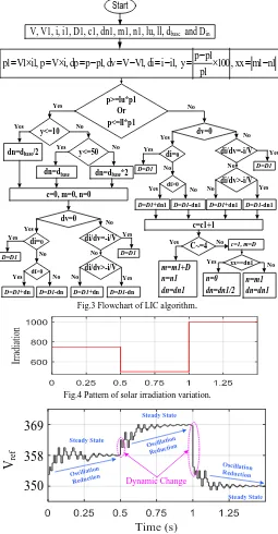
Fig.3 shows the working strategy of LIC technique, which is divided into two parts. The 1st section deals with the steady state condition, where steady-state oscillations are mitigated, by reducing the size of the step change. Moreover, the 2nd section deals with the dynamic condition after that it quickly jumps on the required duty cycle, by increasing the size of the step change. For sensing the condition, an envelope is created in each iteration, whose upper and lower bands are lu and ll, respectively. lu and ll are calculated according to the base step size (dbase), which is taken as a fixed size of step change in
conventional InC. lu and ll are described as,
100 1 100 1 100 oc oc base mpp V lu V d V (10) 100 1 100 1 100 oc oc base mpp V ll V d V (11)
lu p1
p
ll p1
Steady StateConditionelse Dynamic ChangeCondition
(12)
In dynamic change condition, the change in step size is described as,
10, / 2
1 100 50 1 2 base base base
if dn d
p p
ifelse dn d
p
else dn d
(13)
In steady state condition, store addition of first 3 conjugative duty cycles in variable ‘nl’ and, after this store addition of
second 3 conjugative duty cycles in variable ‘ml’. Here dn is calculated as,
1, 0, 1/ 2
else , , 1
if ml nl dn n dn dn
n ml dn dn
(14)
After dn calculation, follow the logic for optimal duty cycle (D) calculation, which is described as,
0 1
0, 0 1
1
/ / 1
, / / 1
1
if di D D
if dv elseif di D D dn
else D D dn
if di dV i V D D
else elseif di dV i V D D dn
else D D dn
(15)
The steady-state and dynamic behaviors of the LIC algorithm are shown in Figs.4-5, which shows oscillation reduction in steady state condition and sudden jump, according to the amount of irradiation change in dynamic conditions.
Start
V, V1, i, i1, D1, c1, dn1, m1, n1, lu, ll, dbase and Din
c=0, m=0, n=0
p>=lu*p1 Or p<=ll*p1 y<=10
p p1
p1 V1 i1, p V i, dp p p1, dv V V1, di i i1, y
100, xx m1 n1
p1
dn=dbase/2 y<=50 dn=dbase dn=dbase*2 c=c1+1 C~=4 m=m1+D n=n1 dn=dn1 c=1, m=D xx==dn1 n=0 dn=dn1/2 n=m1 dn=dn1 Yes Yes Yes Yes Yes No No No No No dv=0 Yes No di>0 D=D1+dnYes No No Yes
di/dv=-i/V di/dv>-i/V No di=0 No Yes Yes
D=D1-dn D=D1+dn D=D1-dn
D=D1 D=D1
dv=0
Yes No
di>0
D=D1+dn1
Yes No No Yes
di/dv=-i/V di/dv>-i/V No di=0 No Yes Yes
D=D1-dn1 D=D1+dn1 D=D1-dn1
D=D1 D=D1
[image:4.612.368.518.47.123.2]Fig.3 Flowchart of LIC algorithm.
Fig.4 Pattern of solar irradiation variation.
Oscillation Reduction Oscillatio n Reduction Oscillation Reduction Dynamic Change Steady State Steady State Steady State
V
re f350
358
369
Fig.5 Steady-state and dynamic behavior of LIC algorithm.
B.Leaky Least Logarithmic Absolute Difference Algorithm
The LLLAD technique is a novel and improved form of LMF (Least Mean Fourth) algorithm, where logarithmic of absolute difference of error is used for quick convergence, and the leaky concept is used for improving the learning process. Schematic of adaptive filter based system identification and weight estimation structure of LLLAD algorithm are shown in Fig.6.
LLLAD smoothly adjusts the conventional cost functions, which minimizes the tracking errors, improves quick pattern recognition, and filter performance. Here, prediction error (ϕa)
of active component of load current for phase ‘a’ is derived as,
Weight Control
Input
Error
Unknown System +
Observation Distortion Desired Response Adaptive Filter +
-Fig.6 System identification model based on LLLAD.
(n) (n) u ( ) ( )
a iLa a n a n
(16) Through proper adjustment and updating of active weight (ξa(n)) of load current for phase ‘a’, the ϕa is minimized, whichis described as,
( ) u ( )
( )
3( 1) 1 ( ) ( )
1 ( ) ( )
a a a
a a a
a a
n n n
n n n
n n
(17)
Where, Ω is leaky learning rate of ξa(n), and α is adaptation
step size, μa(n) is designed parameter of phase ‘a’, which gives
an additional degree of freedom. That is calculated as,
(
1)
( )
(n 1)
a
n
an
a
(18) Where, τ and ϛ are accelerating parameters. ϑ is the autocorrelation parameter. For phase ‘a’, the autocorrelation factor of active component is σa(n), which is described as,
(
1)
( )
1
( )
(
1)
a
n
an
an
an
(19) For better understanding and easy implementation, the block diagram of LLLAD, for ξa(n) generation is shown in Fig.7Unit Delay
Unit Delay
Unit Delay
Unit Delay
ξa(n+1)
iLa(n)
1
Ω μa(n)
ϕa(n)
ϑ (1-ϑ)
σa(n) σa(n+1)
ς
τ μa(n+1)
ξa(n)
u
a(n)
(.)3 α
[image:4.612.45.300.96.586.2]| . | 1
Fig.7 Block diagram of LLLAD algorithm.
In similar way, the active weights (ξb(n), ξc(n)) of load currents
for phase ‘b’ and phase ‘c’ are generated as,
3 (n) (n) u ( ) ( )
( ) u ( ) ( )
( 1) 1 ( ) ( )
1 ( ) ( )
( 1) ( ) (n 1)
( 1) ( ) 1 ( ) ( 1)
b Lb b b
b b b
b b b
b b
b b b
b b b b
i n n
n n n
n n n
n n
n n
n n n n
(20)
3 (n) (n) u ( ) ( )( ) u ( ) ( )
( 1) 1 ( ) ( )
1 ( ) ( )
( 1) ( ) (n 1)
( 1) ( ) 1 ( ) ( 1)
c Lc c c
c c c
c c c
c c
c c c
c c c c
i n n
n n n
n n n
n n
n n
n n n n
(21)
[image:4.612.320.561.342.534.2]O
ut
pu
t
L
ay
er
In
pu
t
L
ay
er
ξa(n) ξb(n) ξc(n)
ξc(n-1)
ξb(n-1) ξa(n-1)
iLa(n) iLb(n)
iLc(n) ϕaϕbϕc
up
μp
α
f f
[image:5.612.86.248.48.162.2]f
Fig.8 The control structure of weight updating process.
C.Comparative Analysis of Proposed LLLAD Algorithm
The comparative analysis of proposed LLLAD control algorithm with most popular adaptive algorithms, such as LMS (Least Mean Square), LMF (Least Mean Fourth), LLMF (Leaky Least Mean Fourth) and normalized LMS (NLMS) is shown in Fig.9.
LMS LMF NLMS LLMF LLLAD
Fig.9 Responses of different algorithms.
For comparative analysis, the unbalanced load situation, where the outage of one phase of load for a period of 0.6s to 1.1s, is considered. Fig.9 shows a comparison in responses of fundamental load component extraction from the load current, which is the resultant active weight component (Φp). In term of
oscillations, Fig.9 shows that during load unbalance, the highest oscillations are in LMS and lowest in LLLAD. Similarly, in terms of settling time and accuracy, Fig.9 depicts that higher settling time and lower accuracy are in LMF, while lower settling time and higher accuracy are in LLLAD, which shows a very good fundamental load component extraction ability of LLLAD algorithm.
IV. RESULTS AND DISCUSSION
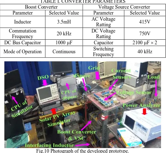
A prototype of the system is developed for performance evaluation of LLLAD based control technique, as shown in Fig.10. To realize the PV characteristic, a solar PV simulator (AMETEK, ETS600x17DPVF) is used, and it is integrated to the actual grid. During integration, for PV power conversion in AC form, load feeding, and for synchronization, a three-phase voltage source converter (VSC) is used. Moreover, for MPPT operation, a novel LIC MPPT algorithm is used, which operates the boost converter. The RC filter and interfacing inductors are used for harmonics and switching ripples mitigation. A DSpace (Digital Signal Processor for Applied and Control Engineering) controller (1202-DSPACE) is used for execution of control techniques. Hall-Effect current (LA-55p) and voltage (LV-25) sensors are used for sensing all signals. For voltage and current measurement, a multimeter 115) is used. A set of power quality analyzers
(Fluke-43B and Hioki-3100) is used for analysis of different harmonic spectra. Differential voltage probes (HAMEG-115Hz) and current probes (Tektronix-A622) are used for voltage and current measurement. A digital storage oscilloscope (DSO7014A) is used for dynamic performance analysis. The converter parameters are given in Table I.
[image:5.612.308.575.160.407.2]The system parameters are, Voc=220V, Isc=16A, Pload=860W, vg=150V, f=50Hz, Lin=5mH, Cfl=10μF, Rfl=10Ω, ϑ=0.2, τ=0.001, ς=0.00001, Ω=0.002, rbase=2V, dbase=0.01,α=1, =1.1.
TABLE I. CONVERTER PARAMETERS
Boost Converter Voltage Source Converter Parameter Selected Value Parameter Selected Value
Inductor 3.5mH AC Voltage
Ratting 415V
Commutation
Frequency 20 kHz
DC Voltage
Ratting 750V
DC Bus Capacitor 1000 F Capacitor 2100 F 2
Mode of Operation Continuous Switching
[image:5.612.54.283.248.394.2]Frequency 40 kHz
Fig.10 Photograph of the developed prototype.
A.Operation under Normal Condition
The steady-state responses of phase ‘a’ are shown in Fig.11, where loads are nonlinear.
(a) (b) (c) (d)
(e) (f) (g)
[image:5.612.318.566.451.713.2](h) (i) (j)
Figs.11(e)-(g) show that successfully power demand of the nonlinear load (Rectifier followed R-L load) is satisfied, which current THD is 27.5%. Moreover, Figs.11(a)-(d) show that after fulfill the load demand, extra 1.74kW power is fed to the grid, where THD of the grid voltage and current are 2.2% and 1.2%, which is well within the permissible limit of 5% according to the IEEE-519 standard [22]. Figs.11(h)-(j) show the waveforms of VSC power, which is supplied by solar PV array and consumed by the load as well as fed to the grid. The THD of VSC current is 9.8%. It shows that VSC supplies required harmonices at PCC to the nonlinear load. Therefore, grid currents are found sinusoidal having THD within the limit.
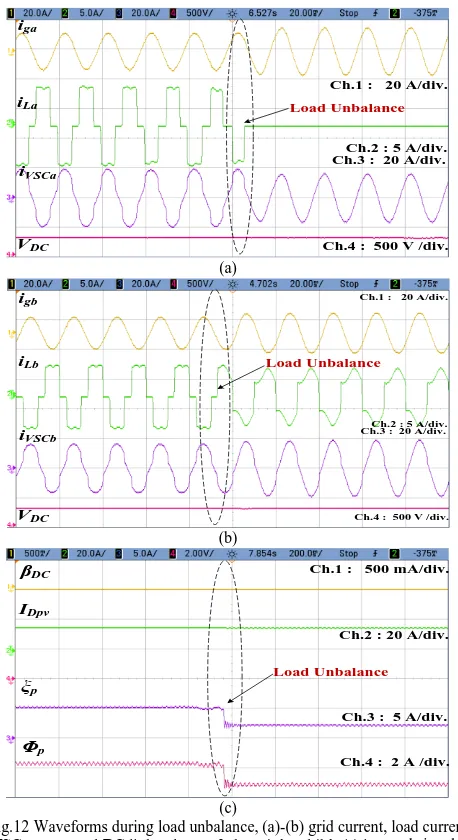
B.Operation under Load Unbalanced Condition
During unbalanced load condition, the load of phase ‘a’ is removed, and its dynamic impact on phase ‘a’ and phase ‘b’, is shown in Fig.12(a), and Fig.12(b), respectively, as well as internal signals, are shown in Fig.12(c).
iga
iLa
iVSCa
Ch.1 : 20 A/div.
Ch.2 : 5 A/div. Ch.3 : 20 A/div.
Ch.4 : 500 V /div.
VDC
Load Unbalance
(a)
igb
iLb
iVSCb
Ch.1 : 20 A/div.
Ch.2 : 5 A/div. Ch.3 : 20 A/div.
Ch.4 : 500 V /div.
VDC
Load Unbalance
(b)
βDC
IDpv
ξp
Ch.1 : 500 mA/div.
Ch.2 : 20 A/div.
Ch.3 : 5 A/div.
Ch.4 : 2 A /div.
Φp
Load Unbalance
(c)
Fig.12 Waveforms during load unbalance, (a)-(b) grid current, load current, VSC current and DC link voltage of phase ‘a’ and ‘b’, (c) internal signals.
Fig.12(a) shows that the load of phase ‘a’ is removed, so the load current becomes zero. However, due to proper control action, grid currents are balanced and sinusoidal, and DC link voltage is constant. Since, due to outage of phase ‘a’ load, the requirement of harmonics current is reduced, so the shape of
VSC current is improved and becomes sinusoidal, as well as nonlinearity of the phase ‘b’ load current is also reduced, which is shown in Fig.12(b). The performance of internal signals during dynamic condition is shown in Fig.12(c), which shows that the DC loss component (βDC) is very low, due to balanced
DC link voltage. Moreover, PV array power dynamic reflection component (IDpv) is constant, because solar irradiation is
assumed constant, and estimated active weight component (ξp)
is reduced as the requirement of active power is reduced. Therefore, the resultant of all components (Φp), is also reduced. C.Operation during Solar PV Array Irradiation Variation
During solar insolation variation condition, it is tested for insolation fall (from 1000W/m2 to 800W/m2), as well as tested for insolation rise (from 800W/m2 to 1000W/m2). The steady-state performances, at solar irradiance 1000W/m2 and 800W/m2 are shown in Fig.13. The dynamic performances for irradiation fall and irradiation rise are given in Fig.14.
Pow er v
s V olta
ge
Current vs Voltage
Ope rati
ng p oint
Pow er v
s V olta
ge
Current vs Voltage
Op erat
ing poi
nt
[image:6.612.314.568.256.696.2](a) (b)
Fig.13 Steady-state performance at insolation (a) 1000W/m2, and (b) 800W/m2.
Ipv Vpv
VDC
Ch.2 : 5 A/div. Ch.1 : 100 V/div.
Ch.4 : 400 V/div. Ch.3 : 500 A /div.
Change in Insolation from 1000 W/m2 to 800 W/m2
Ppv
MPP Tracking By LIC
Pattern-1
Pattern-2
TMPPT=0.38s
X-axis: 0.2s/div.
(a)
Ipv Vpv
VDC
Ch.2 : 5 A/div. Ch.1 : 100 V/div.
Ch.4 : 400 V/div. Ch.3 : 500 A /div. Change in Insolation from
800 W/m2
to 1000 W/m2
Ppv MPP Tracking
By LIC
Pattern-1
Pattern-2
TMPPT=0.40s
X-axis: 0.2s/div.
[image:6.612.57.286.257.677.2](b)
performances in insolation rise and fall condition, at irradiation 1000W/m2 and 800W/m2 are oscillation free, which is only due to learning based duty cycle reduction process of LIC algorithm. After irradiation change, it has taken approximately 0.39s to track the MPP, which shows the excellent dynamic performance of proposed MPPT technique. In both conditions, the tracking efficiencies are 99.99% and 99.99%, which are shown in Fig.13 as well as the red boundary on Fig.13 highlights the %MPPT. These MPPT efficiencies are approximately close to 100%, which shows the accuracy of the LIC algorithm.
1)Comparative MPPT Analysis with State of Art Technique
On same circuitry condition, for comparative analysis, the most recent technique is considered, which is modified power ratio variable-step based P&O algorithm (MPRVPO) [23]. The obtained waveforms of MPRVPO algorithm for irradiation fall and irradiation rise condition are shown in Fig.15.
Ipv Vpv
VDC
Ch.2 : 2 A/div. Ch.1 : 20 V/div.
Ch.4 : 400 V/div. Ch.3 : 200 A /div.
Change in Insolation from 1000 W/m2 to 800 W/m2
Ppv
MPP Tracking By MPRVPO
Pattern-1 TMPPT=1.8s Pattern-2
X-axis: 1s/div.
(a)
Ipv Vpv
VDC
Ch.2 : 2 A/div. Ch.1 : 20 V/div.
Ch.4 : 400 V/div. Ch.3 : 200 A /div.
Change in Insolation from 800 W/m2 to 1000 W/m2
Ppv
MPP Tracking By MPRVPO
Pattern-1 Pattern-2
TMPPT=1.8s
X-axis: 1s/div.
[image:7.612.326.557.45.312.2](b)
Fig.15 Waveforms of MPRVPO algorithm during (a) insolation fall and (b) insolation rise condition.
Fig.14 and Fig.15 show that LIC algorithm and MPRVPO algorithm, both MPPT algorithms are capable to track the MPP. However, the average tracking duration of MPRVPO algorithm is 1.8s, while LIC algorithm has reached the GMM only in 0.39s. Moreover, waveforms clearly show that the steady state oscillation in MPRVPO algorithm is very high, while in LIC algorithm, it is negligible. Therefore, LIC MPPT algorithms shows the superiority on state of the art techniques.
D.Operation under Grid-Voltage Fluctuations Condition
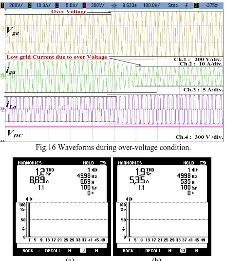
During testing for grid voltages fluctuation, the overvoltage condition is considered. In this condition, the fluctuation in grid voltage of approximately 10% is taken, which test responses of phase ‘a’ are shown in Fig.16. Moreover, harmonics spectra of grid current of the phase ‘a’ are shown in Fig.17.
Vga
iga
iLa
Ch.1 : 200 V/div. Ch.2 : 10 A/div.
Ch.3 : 5 A/div.
Ch.4 : 300 V /div.
VDC
Low grid Current due to over Voltage Over Voltage
Fig.16 Waveforms during over-voltage condition.
(a) (b) Fig.17 Harmonics spectra of grid current for phase ‘a’, during (a) normal
condition, and (b) overvoltage condition.
The waveforms of overvoltage depict that, the voltage at PCC is increased, so due to constant supply power, the iga is
decreased. Moreover, since PL (load power) is directly
propositional to the square of vPCC (PCC voltage), so PL, as
well as iL, is increased. However, due to strong control ability,
the VDC is regulated to the desired value, and a balanced power
is fed to the load, which is shown in Fig.16. Moreover, after fulfill the load demand, the extra power is supplied to the grid. During this process, the THD of iga is still low and within the
permissible limit of 5% according to the IEEE-519 standard[22][24], which is shown in Fig.17. Similarly, during under-voltage condition, the power management and the THD of grid currents are good and within the permissible limit.
E.Operation during Grid Voltage Imbalance Condition
The dynamic behavior of the system under the imbalance grid voltages condition, is shown in Fig.18 and vector diagram of all components are shown in Fig.19.
[image:7.612.52.293.252.546.2]condition. Moreover, Fig.19 shows that a phase angle difference, between grid voltages, is not 120◦, which depicts the phase angle imbalance. However, in this situation, three phase currents are 6.906A, 6.900A, and 6.903A, and the phase angle difference, between the grid currents, is 120◦, which show balanced supply currents. Moreover, the THDs of grid currents are below 5%, which shows a satisfactory performance.
Fig.19 Vectors of three-phase voltage and current during phase imbalance.
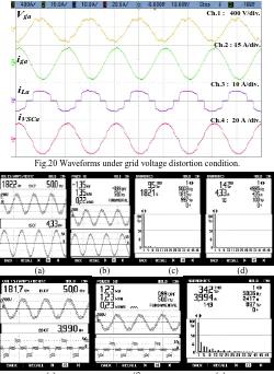
F.Operation during Grid Voltage Distortion Condition
Performances under grid voltage distortion condition for phase ‘a’, are shown in Fig.20, and analyzed by using a power analyzer, which obtained waveforms are shown in Fig.21.
Vga
iga
iLa
Ch.1 : 400 V/div.
Ch.2 : 15 A/div.
Ch.3 : 10 A/div.
Ch.4 : 20 A /div.
iVSCa
Fig.20 Waveforms under grid voltage distortion condition.
(a) (b) (c) (d)
(e) (f) (g)
Fig.21 Waveforms of, (a)-(d) phase ‘a’ grid voltage, current, power and its harmonics spectrum, and (e)-(f) phase ‘a’ load voltage, current, power and its harmonics spectrum, during grid voltage distortion condition.
Here THDs of distorted vga and THD of nonlinear load
current are 9.5%, and 34.2%, which are shown in Fig.21(c) and Fig.21(g), respectively. Moreover, for testing of proposed control technique in a highly complex situation, the overvoltage condition is applied, at distorted grid voltage condition. In this highly nonlinear situation, the proposed control technique has performed very well and properly fed the load. After fulfill the load demand, an extra power is transferred to the grid, where THD of grid current is only 1.4%, with unity power factor, as is shown in Fig.21(d).
1)Comparative Analysis under Distorted Grid Voltage and Nonlinear Load Condition with State of Art Techniques
For comparative analysis, on the same circuitry condition, the most popular techniques, ANF, KF and proposed LLLAD technique are tested. During testing, the nonlinear load is connected, at PCC and distorted grid voltage situation is taken. Here the objective of the controller is, first the load is fed, and after feeding the load, the rest power is supplied to the grid. In this situation, the achieved THD of iga by using ANF based
control technique is very poor, that is 4.7%. Moreover, in the case of KF based control technique, the THD of iga is
improved, that is 3.8%. However, the obtained THD of iga by
using LLLAD technique is only 1.4%, which depicts a significant difference, in comparison to state of art techniques.
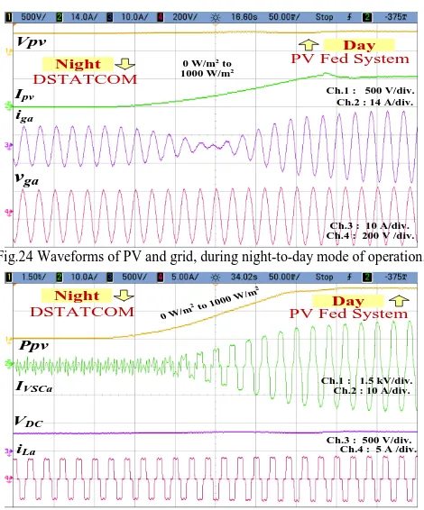
G.Operation during Day-to-Night Mode
In day-to-night condition, during the daytime, solar PV power is used to meet the load demand, and if some power is left, then it is fed into the grid. Moreover, during the night time, when solar power is zero, then the load demand is met by taking power from the grid, and VSC acts as a DSTATCOM, which provides reactive power support. These all performances for day-to-night mode, are shown in Figs.22-23 and for night-to-day mode are shown in Figs.24-25.
Vpv Ipv
iga
Ch.1 : 500 V/div.
Ch.2 : 15 A/div. Ch.3 : 10 A/div.
Ch.4 : 200 V /div.
vga
Day
Night
PV Fed System
DSTATCOM
1000 W/m2
to 0 W/m2
Fig.22 Waveforms of PV and grid, during day-to-night mode of operation.
Ppv
IVSCa
VDC
Ch.1 : 5.0 kA/div. Ch.2 : 10 A/div.
Ch.3 : 500 V/div. Ch.4 : 5 A /div.
iLa
Day
Night
PV Fed System
DSTATCOM
1000 W/m2
to 0 W/m2
[image:8.612.47.297.359.701.2] [image:8.612.320.562.450.726.2]In Fig.22 and Fig.24, during the daytime, iga and vga are out of
phase, which shows that the power is fed into the grid. Moreover, during night time, iga and vga are in the same phase,
which shows that power is supplied from the grid.
Vpv
Ipv
iga
Ch.1 : 500 V/div. Ch.2 : 14 A/div.
Ch.3 : 10 A/div. Ch.4 : 200 V /div.
vga
Day
Night PV Fed System
DSTATCOM
0 W/m2 to
1000 W/m2
Fig.24 Waveforms of PV and grid, during night-to-day mode of operation.
Ppv
IVSCa
VDC
Ch.1 : 1.5 kV/div. Ch.2 : 10 A/div.
Ch.3 : 500 V/div. Ch.4 : 5 A /div.
iLa
Day Night
PV Fed System
DSTATCOM 0 W/m
2 to 1000 W/
m2
Fig.25 Waveforms of PV and VSC, during the night-to-day mode of operation. The compensation behavior of VSC at night time is shown in Fig.23 and Fig.25, where it behaves like DSTATCOM. It increases the utility of the system. Moreover, in both conditions, the DC link voltage is maintained, which has only possible due to the strong controlling ability of the LLLAD based VSC control and LIC based MPPT algorithm.
V. CONCLUSION
A novel control technique namely Leaky Least Logarithmic Absolute Difference (LLLAD) based control algorithm and Learning based Incremental Conductance (LIC) MPPT (Maximum Power Point Tracking) algorithm, for grid-tied solar PV system have been developed and implemented on the developed prototype, where the nonlinear/linear loads have been connected at PCC. The MPPT by LIC has been shown the very good steady-state as well as dynamic performance on different irradiation conditions. The LLLAD control enhances the power management ability with improved power quality, for a two-stage three-phase grid integrated solar PV system, where distribution network is subjected to nonlinear loading at, under-voltage, over-voltage, phase imbalance and the distorted voltage at PCC. The simple architecture of the LLLAD makes easy to implement and helps in computational complexity reduction as well as quick dynamic performance. The performance of LLLAD has also been evaluated on day to night mode of operation. During daytime, the system behaves as PV tied grid system, where control technique provides load balancing, power factor correction, harmonics filtering and mitigation of other power quality issues. However, when solar irradiation is zero, in the night time, DC link capacitor and VSC act as DSTATCOM, which enhances the utilization factor
of the system. Test results have shown its satisfactory performance at unity power factor (UPF) under abnormal grid conditions, such as distortion in grid voltage at nonlinear and unbalanced load at PCC. Moreover, THDs in grid voltages and grid currents have been observed within permissible limit, according to the IEEE-519 standard.
REFERENCES
[1] G. Velasco-Quesada, F. Guinjoan-Gispert, R. Pique-Lopez, M. Roman-Lumbreras and A. Conesa-Roca, "Electrical PV Array Reconfiguration Strategy for Energy Extraction Improvement in Grid-Connected PV Systems," IEEE Trans. Industrial Electronics, vol. 56, no. 11, pp. 4319-4331, Nov. 2009.
[2] A. Sangwongwanich, Y. Yang and F. Blaabjerg, "A Sensorless Power Reserve Control Strategy for Two-Stage Grid-Connected PV Systems,"
IEEE Trans. Power Electr., vol. 32, no. 11, pp. 8559-8569, Nov. 2017.
[3] E. Roman, R. Alonso, P. Ibanez, S. Elorduizapatarietxe and D. Goitia, "Intelligent PV Module for Grid-Connected PV Systems," IEEE Trans. Industrial Electronics, vol. 53, no. 4, pp. 1066-1073, June 2006. [4] S. Somkun and V. Chunkag, “Unified Unbalanced Synchronous
Reference Frame Current Control for Single-Phase Grid-Connected Voltage-Source Converters,” IEEE Trans. Industrial Electronics, vol. 63, no. 9, pp. 5425-5436, Sept. 2016.
[5] P. García, C. A. García, L. M. Fernández, F. Llorens and F. Jurado, "ANFIS-Based Control of a Grid-Connected Hybrid System Integrating Renewable Energies, Hydrogen and Batteries," IEEE Trans. Industrial Informatics, vol. 10, no. 2, pp. 1107-1117, May 2014.
[6] X. Fu and S. Li, "Control of Single-Phase Grid-Connected Converters With LCL Filters Using Recurrent Neural Network and Conventional Control Methods," IEEE Trans. Power Electronics, vol. 31, no. 7, pp. 5354-5364, July 2016.
[7] T. Z. Bei and P. Wang, "Robust frequency-locked loop algorithm for grid synchronisation of single-phase applications under distorted grid conditions," IET Gen., Trans. & Dist., vol. 10, no. 11, pp. 2593-2600, April 2016.
[8] H. Yi, X. Wang, F. Blaabjerg and F. Zhuo, "Impedance Analysis of SOGI-FLL-Based Grid Synchronization," IEEE Trans. Power Electronics, vol. 32, no. 10, pp. 7409-7413, Oct. 2017.
[9] R. Panigrahi and B. Subudhi, "Performance Enhancement of Shunt Active Power Filter Using a Kalman Filter-Based H∞ Control Strategy,"
IEEE Trans. Power Electr., vol. 32, no. 4, pp. 2622-2630, April 2017. [10] C. A. Busada, S. Gomez Jorge, A. E. Leon and J. A. Solsona, "Current
Controller Based on Reduced Order Generalized Integrators for Distributed Generation Systems," IEEE Trans. Industrial Electronics, vol. 59, no. 7, pp. 2898-2909, July 2012.
[11] H. Karimipour and V. Dinavahi, "Extended Kalman Filter-Based Parallel Dynamic State Estimation," IEEE Trans. Smart Grid, vol. 6, no. 3, pp. 1539-1549, May 2015.
[12] G. Rigatos, P. Siano, N. Zervos and C. Cecati, "Decentralised control of parallel inverters connected to microgrid using the derivative-free non-linear Kalman filter," IET Power Electr., vol. 8, no. 7, pp. 1164-1180, July 2015.
[13] C. A. Rojas, M. Aguirre, S. Kouro, T. Geyer and E. Gutierrez, "Leakage Current Mitigation in Photovoltaic String Inverter Using Predictive Control With Fixed Average Switching Frequency," IEEE Trans. Industrial Electronics, vol. 64, no. 12, pp. 9344-9354, Dec. 2017. [14] A. Vidal, F. D. Freijedo, A. G. Yepes, J. Malvar, Ó. López and J.
Doval-Gandoy, “Transient response evaluation of stationary-frame resonant current controllers for grid-connected applications,” IET Power Electronics, vol. 7, no. 7, pp. 1714-1724, July 2014.
[15] M. A. Elgendy, B. Zahawi and D. J. Atkinson, "Assessment of the Incremental Conductance Maximum Power Point Tracking Algorithm,"
IEEE Trans. Sustainable Energy, vol. 4, no. 1, pp. 108-117, Jan. 2013. [16] J. Ahmed and Z. Salam, "A Modified P&O Maximum Power Point
Tracking Method With Reduced Steady-State Oscillation and Improved Tracking Efficiency," IEEE Trans. Sust. Ener., vol. 7, no. 4, pp. 1506-1515, Oct. 2016.
[17] A. Thangavelu, S. Vairakannu and D. Parvathyshankar, "Linear open circuit voltage-variable step-size-incremental conductance strategy-based hybrid MPPT controller for remote power applications," IET Power Electronics, vol. 10, no. 11, pp. 1363-1376, Sep. 2017.
[image:9.612.54.289.93.376.2]Fuzzy Model-Based Approach," IEEE Journal of Emerging and Selected Topics in Power Electronics, vol. 6, no. 1, pp. 292-299, March 2018. [19] K. Jyotheeswara Reddy and N. Sudhakar, "High Voltage Gain Interleaved
Boost Converter With Neural Network Based MPPT Controller for Fuel Cell Based Electric Vehicle Applications," IEEE Access, vol. 6, pp. 3899-3908, June 2018.
[20] C. Jain and B. Singh, “An Adjustable DC Link Voltage Based Control of Multifunctional Grid Interfaced Solar PV System,” IEEE Journal of Emer. and Sel. Topics in Power Electron., vol. 10, no. 3, pp. 112-121, May 2016.
[21] N. Kumar, I. Hussain, B. Singh and B. K. Panigrahi, "Normal Harmonic Search Algorithm Based MPPT for Solar PV System and Integrated with
Grid using Reduced Sensor Approach and PNKLMS Algorithm," IEEE Trans. Industry Appl., vol. 54, no. 6, pp. 6343-6352, Nov.-Dec. 2018. [22] IEEE Draft Guide for Applying Harmonic Limits on Power Systems,"
IEEE P519.1/D12, July 2012, pp.1-124, Feb. 2015.
[23] M. Rezkallah, A. Chandra, M. Tremblay and H. Ibrahim, "Experimental Implementation of an APC with Enhanced MPPT for Standalone Solar Photovoltaic based Water Pumping Station," IEEE Trans. Sustainable Energy, 2018 (Early Access).