Innovative All Composite Multi-Pultrusion Truss System for Stressed
Arch Deployable Shelters
T. Omar1, G. Van Erp1 , T Aravinthan1 , P. Key2 1
Fibre Composite Design and Development; University of Southern Queensland, Toowoomba, QLD, Australia.
2
Kencana Strarch Asia Pacific, Kuala Lumpur, Malaysia.
Abstract
Trusses are one of the successful structural forms that have been utilised, at extended scale, since the nineteen century. Fibre composite materials are relatively new to civil engineering applications. The increased interest in using composites in civil applications can be attributed to advantages when compared to other construction materials that offset their associated costs. Using conventional approaches for truss systems in composite materials can undermine their efficiency. This is mainly due to concentration of stresses at connections which usually govern the truss design.
The Military Modular Shelter System (M2S2) initiative is a research project that aims to develop a fibre composite re-deployable arched shelter system with rigid PVC or fabric cladding. The main frames are formed from modular fibre composite panels that are connected and stressed into position by prestressing cables. Different geometries can be obtained using this system by changing the number of panels per frame and the packer sizes between panels.
This paper presents the development and testing of innovative fibre composite truss modules that were investigated as part of this project. The truss system is based on using multi-pultrusion sections for the chord and vertical members. Truss bracing is provided by a double skin laminated web. This structure offers many advantages including semi-ductile failure that occurred outside the joint area and ease of manufacturing. In spite of being developed for the M2S2 system, the concept is similarly applicable as a general purpose truss system.
Keywords: Shelters, Composites, Deployable, Hanger, Truss
1 Introduction
Trusses are one of the successful structural forms that have been utilised, at extended scale, since the nineteen century. Being made originally from timber, they were easy to manufacture and assemble for pedestrian and railway bridges. The stiffness and strength of a truss is derived from its geometry (especially its depth) and axial stiffness of its members. Fibre composite materials are relatively new to civil applications. The increased interest in using composites in civil applications can be attributed to advantages when compared to other construction materials that offset their associated costs. Their high strength/weight ratio, free formability and resistance to corrosion and fatigue are among these advantages.
(Gantes, 2001). In addition to these basic requirements, they should also satisfy the deployability requirements of being able to be dismantled, stored and transported in a compact form. They should have an inherent deploying mechanism that allows the transition between the deployed status and the dismantled status and vice versa in a relatively quick and easy manner.
Deployable shelters are an important application of deployable structures. They are needed for military applications, temporary aircraft maintenance hangers, aid relief and remote structures. In recent times the need for these types of structures has increased significantly. This has prompted Strarch International to start a research project into a more efficient modular shelter system. The M2S2 initiative concentrates on the development of an all fibre composite light-weight re-deployable arched shelter system with rigid PVC or fabric cladding. The main frames are formed from modular fibre composite panels which are connected and stressed into position by prestressing cables. Different geometries can be obtained using this system by changing the number of panels per frame and the packer sizes between panels.
This paper starts with a general discussion of the M2S2 concept followed by a review of the currently available composite truss systems. A detailed discussion of the development and testing of an innovative fibre composite truss module is then presented.
2 M
2S
2Concept
[image:2.595.182.419.573.720.2]The concept of M2S2 is based on the stressed arch concept that was originally used in Strarch steel arches (Strarch, 1999). However, it overcomes the deployability short comings in this system by utilizing discrete truss panels to form the frames. Rotations between adjacent panels occur at discrete inter-panel joints in the top and bottom chords (Omar et al, 2006). Standard panels are connected to each other in an up-right position at ground level to assemble each frame (Figure 1). One side of the frames is fixed to the foundation, while the other is free to move horizontally during the prestressing procedures. The prestressing cables are threaded through the bottom chord. Roof sheeting and other services are assembled while the frames are still on the ground prior to carrying out any prestressing (the assembly stage). After finishing the installation of services, the frames are stressed into an arch shape using prestressing cables. The bottom chord has gaps between the panels to allow for changing of the geometry to an arch shape during the prestressing process (Erection stage). Finalizing the stressing process, the prestressing cables are blocked and the moveable frame support is fixed, the shelter is complete and ready to use (Deployed stage).
Figure 1: M2S2 Frame components
from 200mm to 220mm changes the frame dimensions, in the erected position, from 36.7mWx12.1mH to 40.0mWx10.1mH. This ability to change the geometry of the structure with little effort is a major advantage of this new system.
In conducting preliminary analysis, the maximum member forces for a 35m span frame in a non-cyclonic zone B, AS/NZS 1170.2-2002 (Standards Australia, 2002), are shown in Table 1. As can be noted, due to the arch geometry, the shelter frames are mainly subjected to axial forces. In addition, shear and bending moments are generated in the case of un-symmetric loading.
Table 1: Serviceability limit state member forces
Member Max Force (kN)*
Top chord -200 Bot chord -290 Verticals +30 Diagonals +45
* Refer to (Omar et al, 2006) for loading scenarios of deployable shelters.
3 2D-Truss Systems in Fibre Composites
[image:3.595.169.428.521.692.2]Composite truss systems have been used in few forms. The first form is the conventional truss system where pultrusion sections are commonly used for the truss members with bolted and/or adhesive joints for the connections. For this type of construction, the connections usually govern the strength of the structure (Turvey, 2000). Since the serviceability limit state of deflection is generally the governing limit state, the pultruded sections used are not usually stressed to their limit. Conventional composite trusses are used for pedestrian bridges and roof trusses. A typical bridge system of this category is the Pontresina Bridge that crosses the Flanz River in Switzerland, Figure 2. The bridge was constructed in the 1997 as a temporary bridge, installed each year in autumn and removed in spring. It consists of two truss girders that span 2x12.5m. The truss joints are adhesively bonded on one span and bolted in the other span. Cross diagonal bracing system is used to reduce the joint forces and provide redundancy in the glued span (Keller, 2001).
The non-conventional truss systems are that composite driven. In this category, the structural form of the truss suited the properties of composites by trying to avoid concentration of stresses. In this category, many composite bridge decks have been developed in the last decade. Most of the currently available decks are constructed using pultruded shapes assemblies that are adhesively bonded to form the deck structure. The flexibility of these systems is obtained by changing the constituents of the shapes (fibre type and architecture) or by changing the cross section of the shape. The popularity of these systems is mainly due to their advantages in strength and stiffness per unit weight, when compared to reinforced concrete decks. These advantages allow increasing the live load rating of the bridges with less weight (Bakis, 2002).
EZSpan is a typical application of this system which was developed by Atlantic Research Corp (ARC). The system is designed for application to the Landing Ship Quay/Causeway (LSQ/C) and Mobile Offshore Base (MOB) programs of the Defence Advanced Research Projects Administration (DARPA). The truss spans 3.05m with unit weight of 98kg/m2 (Brown, 2001). Triangular elements are fabricated using a single, thick ply of 3D braided fibreglass textile drawn through the pultrusion die, Figure 3. The triangular pultrusions are bonded together with the facing sheets.
[image:4.595.135.461.312.425.2]Another non-conventional approach for composite trusses was proposed by Humphreys et al (1999). The Monocoque Fibre Composite (MFC) truss concept is based on using two planner skins that contain the fibre structure of the truss members. The skins are separated by core material, Figure 4. The truss derives its strength from the reinforcing skins while the core material separated the skins to provide lateral stiffness for the members’ stability. Due to the difficulty in lapping the joints, Humphreys introduced the concept of strength and fill layers. Strength layer is the layer where fibres are extended through the joint while the fill layers stop at the member intersections. In using different sequence of strength and fill layers, each of the truss members can be connected to the joint (Figure 5).
Figure 3: EZSpan System (Brown, 2001)
Top skin
[image:4.595.112.448.591.718.2]Bottom skin Pultruded triangles
4 Pre-investigations of the Truss System
Due to the level of member forces, none of the truss concepts found in the literature were considered suitable for the M2S2 concept. Hence, early work focused on the development of different fibre composite truss alternatives. The parameters that were considered include; overall structural system, fabrication techniques, structural performance (such as capacity, ductility, stability, durability & fire resistance) and operational considerations (such as handling, assembly, dismantling & storage). In investigating different panel concepts, a weight limit of 20kg/m was set in order to satisfy handling and manoeuvring requirements. To accommodate the prestressing cables, the top and bottom chord of the panel have to be of hollow section.
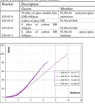
[image:5.595.116.480.79.198.2] [image:5.595.303.495.501.737.2]With the above points in mind, investigations of the new panel system started by considering conventional truss alternatives with a diagonal member connected to gussets, by adhesive bonding (Figure 6). Prior to constructing a prototype panel, the diagonal connection to the gusset was investigated to verify its behaviour (Figure 7). Two parameters were considered in this investigation, the effect of the gusset stiffness and the connecting member. Due to the limitation in the clamping size of the testing machine, the diagonal box member was replaced by 50x10mm flat, Table 2. The load deflection curves of the tested brackets are shown in Figure 8.
Figure 5: MFC concept of strength and fill layers - Humphrey et al (1999)
2 SHS50x50x5
[image:5.595.79.261.562.734.2]Gusset
Figure 6: Flat sided panel - initial concept
Load/Defl
R R
Table 2 Description of the joint brackets Bracket Description
Gusset Member
429-01-0
10 plies of glass double bias (DB) 600gsm
FL50x10 polyester/glass pultrusion
429-02-0 6 plies of glass DB FL50x10 Pult
429-03-0
4 plies of carbon DB
420gsm FL50x10 Pult
429-03-1
4 plies of carbon DB 420gsm
FL50x10 epoxy/glass laminate
Generally, brackets failed in a brittle mode with complete loss of strength. Failure occurred at the interface between the gusset and the loading member by interlaminar shearing of the loaded member. Increasing the stiffness of the gusset increases the joint capacity. In increasing the number of plies (01-0) or using carbon fibres (03-0) the bracket capacity increased from 59.9kN (02-0) to 77.7kN (130%) and 83.2kN (139%) respectively. The adherent resin affects the capacity of the joint. Using epoxy for the member increased the joint capacity from 83.2kN (03-0) to 99.3kN (119%) for 03-1. Accordingly, it can be seen that both the adherent resin system and the gusset stiffness affects the ultimate strength of the tested brackets. However, in all cases, the average failure strength was low (maximum of 6.6MPa for 429-03-1 bracket). The joint efficiency of this bracket is 42% (Clarke, 1996). The sudden failure of the brackets is another problem of this system. Accordingly, it can be concluded that conventional use of gusset in the panel system is not efficient and does not suite using composites for the truss system.
5 Innovative Truss System for M
2S
2Previous investigations have shown that it is recommended to have panels with flat-sided standard components, extended joint areas and structural redundancy (Omar et al, 2006). The concept of a multi-pultrusion truss (MPT) was introduced to overcome the above mentioned challenges. The MPT uses three (or more) hollow pultruded section for the top and bottom chords and the vertical members (Figure 9). The shear capacity of the panel is provided by two laminated skins that are anchored in between the pultrusions using an epoxy adhesive. The advantages of this approach can be summarized as follows:
- Pultrusions are among the most efficient and economical forms in composite sections; 0
20 40 60 80 100 120
0 2 4 6 8 10 12
Defl(mm)
F(
k
N
)
429-01-0 - Fu=77.7
429-02-0 - Fu=59.9
429-03-0 - Fu=83.2
429-03-1 - Fu=99.3
- Using multi-sections significantly improves the lateral stability of the members in compression;
- Local buckling resistance of the top chord is good due to the use of multiple rather stocky pultruded sections;
- Multiple hollow pultrusions allow for more than one cable to conduct the prestressing process. It also provides much more area to join with the adjacent panels;
- The laminated web acts as a diaphragm that is mainly loaded in tension, the favorite loading type for fibre composites;
- Having a diaphragm avoids stress concentrations in the adhesive layers and in the connecting parts by allowing force transmission through the continuous adhesive layers; - Forces in the web are not interrupted by localized joints. However, they are directly
transferred to chord and vertical members;
- The diaphragm web provides significant redundancy in the case of tensile failure of the laminated web;
- The panel durability and fire resistance is expected to improve due to eliminating the exposed joint area, by extending the web skins between pultrusions;
- The proposed panel is simple to manufacture;
[image:7.595.203.408.382.564.2]- This concept was mainly developed for M2S2. However, it can be used as a general truss concept.
Figure 9: Multi-pultrusion truss concept
6 MPT Panel Test
Figure 10: Test panel geometry and strain gauge positions
7 MPT Panel Test Results
The tested panel showed good performance. The load-deflection curve (Figure 11) shows that the panel retains a partial load carrying capacity of about 60% of the ultimate capacity after failure of the main tension fibre s. Failure initiated at the top corner of the diaphragm, due to the combined tension in the diagonal direction and compression in the perpendicular direction (Figure 12). Compressive forces were due to the confinement of the web with the tendency of the angle between the vertical and top chord members to reduce under the applied loads. Failure propagated along the inner faces of the vertical and top chord following the pattern of the formed wave of the buckled web. No failure was observed in the adhesive layers. This is a favorable result as adhesive failure is inherently brittle. The semi ductile behaviour of the panel is attributed to the way in which the web carries the tensile loads. Figure 13 shows the tensile forces in the web predicted by the FE model at ultimate capacity. As shown, the middle 40% of the web carries 80% of the total tensile force. On reaching the ultimate strength, failure occurs in the middle region of the web. This releases some of the stored energy and reduces the panel stiffness. Regions adjacent to the failed section continue to carry load until reaching failure and so on.In releasing the applied load, the panel recovered most of its deflection (in spite of rupturing of the web).
0 20 40 60 80 100 120 140 160 180 200
0 5 10 15 20 25
Defl(m m )
Ld
(k
N
)
[image:8.595.185.409.532.683.2]Figure 12: Test panel failure initiation and propagation
0% 10% 20% 30% 40% 50% 60% 70% 80% 90% 100% 110%
-50% -40% -30% -20% -10% 0% 10% 20% 30% 40% 50%
% X Dim
%
For
c
e
[image:9.595.185.414.58.230.2]%Nt1_13-03 %Nt1_13-03
Figure 13: Diagonal force integrated along the cross diagonal
The strain gauge records, Figure 14 to Figure 17, show that:
- Up to the ultimate load, the load-deflection curve and the strain-deflection curves are mostly linear;
- The system is effective in distributing forces between the panel frames, as equal strains were recorded across the panel at different locations;
- Strain distributions across the verticals changed from tension at the outer surface (SG17 to SG19, Figure 16) to compression at the inner face (SG31, Figure 16) with equal shift from the centre line gauge SG20. This indicates that the verticals are subjected to bending stresses;
- Strains recorded by top chord gauges (SG11-SG13, Figure 14) and verticals gauges (SG17-SG19, Figure 17) are identical with a slight change at the post failure region. This behaviour is expected as both gauges are symmetrically located about the tensile diagonal in the web;
- Compressive strain at mid-span top chord (SG34, Figure 14) is approximately half the tensile strains (SG14-SG16, Figure 15) at the bottom chord. This can be attributed to bending stresses in the chords. As expected, both chords have similar axial force components albeit with different signs;
- In Figure 11, at ultimate load, SG34 recorded less strain compared to quarter span top chord gauges (SG11-SG13). With the start of failure propagation, SG34 strain level increased while SG11-SG13 reduced. This behaviour can be attributed to the level of stress in the web laminate that applies both axial and shear forces on the connecting frame members. This results in bending moment and axial forces in such members. Combined stresses were higher at SG11-SG13 compared to SG34. After failure, stresses in the web
[image:9.595.186.412.237.392.2]laminate reduced, due to rupturing of the web, leading to reducing strain in SG11-SG13. The increase in SG34 can be attributed to an increase in the member curvature with the less stiff damaged panel;
- Web strains (SG37-SG38) in tension are significantly higher than the strains recorded in the pultrusions. Nominal compressive stresses are recorded in the other diagonal direction (SG40). This validates the expected behaviour of tension-only bracing web.
-4000 -3500 -3000 -2500 -2000 -1500 -1000 -500 0 500
0 5 10 15 20 25
Defl(mm) St ra in (μ s)
[image:10.595.183.411.127.652.2]_SG[11] _SG[12] _SG[13] _SG[34]
Figure 14: Strain-deflection curve at top chord
-1000 0 1000 2000 3000 4000 5000
0 5 10 15 20 25
Defl(mm) St ra in (μ s)
_SG[14] _SG[15] _SG[16] _SG[35]
Figure 15: Strain-deflection curve at bottom chord
-2500 -2000 -1500 -1000 -500 0 500 1000
0 5 10 15 20 25
Defl(mm) St ra in (μ s)
[image:10.595.184.412.161.314.2]_SG[17] _SG[19] _SG[20] _SG[31]
-2000 -1000 0 1000 2000 3000 4000 5000 6000 7000 8000
0 5 10 15 20 25
Defl(mm)
St
ra
in
(μ
s)
[image:11.595.184.411.55.205.2]_SG[37] _SG[38] _SG[39] _SG[40]
Figure 17: Strain-deflection curve at web laminate
8 Conclusions
The demanding performance requirements of modern deployable shelters have driven the development of more sophisticated structural forms and solutions. The M2S2 deployable shelter concept combines the effectiveness of an arch as a structural form, post tensioning technology and light weight composite materials. This innovative approach provides a flexible deployable shelter system that satisfies the deployment requirements and the flexibility needed by the end users. The flexibility is achieved by using modular panels of manageable size and weight which are within the carrying capacity of two persons. By using different size packers in the bottom chord, different structural configurations can be obtained with little effort.
Using conventional approaches with fibre composites can produce inefficient structural systems. It important for the engineers/researches to understand the main characteristics of the materials used to provide innovative solutions using these sophisticated materials. The multi-pultrusion truss module showed good load carrying characteristics. Providing an alternate load path after failure, no failure in the adhesive layers, recovering original geometry after removal of applied loads, ease of manufacturing and the possibility of having different prestressing cables are among the important characteristics of this system. Further research work is needed to investigate the detailed structural behaviour of this truss concept.
9 References
Bakis, C. E., Brown, V. L., Cosenza, E., Davalos, J. F., Lesko, J. J., Machida, A., Rizkalla, S. H., and Triantafillou, T. C. (2002). Fibre-reinforced polymer composites for construction, State-of-the-art review. J for Composites for Construction, 6(2), 73-87.
Brown, R. T., and Zureick, A. (2001). Lightweight composite truss section decking. Marine Structures, 14, 115-132.
Clarke, M. J., and Hancock, G. J. Behaviour and Design of stressed-arch (Strarch) frames. IASS-ASCE International Symposium 1994 on spatial, lattice and tension structures, Atlanta, 200-209. Clarke, M. J., and Hancock, G. J. (1995). Tests and nonlinear analysis of small scale stressed arch frames. J of Structural Engineering, 121(2), 187-200.
Humphreys, M. F. (2003). Development and structural investigation of monocoque fibre composite trusses, Queensland University of Technology, Brisbane.
Humphreys, M. F., Van Erp, G. M., and Tranberg, C. (1999). The structural behaviour of monocoque fibre composite truss joints. Advanced Composite Letters, 8(4), 173-180.
Keller, T. (2001). Recent all-composite and hybrid fibre-reinforced polymer bridges and buildings."
Prog. Structural Engineering Materials, 3, 132-140.
MCCDC. (1990). Required operational capability (ROC) for a marine corps expeditionary aircraft maintenance shelter. LOG 33.1A, Virginia.
NCEL. Frame supported tensioned structure (FSTS) hanger concept. Department of Navy - US, California.
Omart, T., Heldt, T., Key, P., and Van Erp, G. M. (2006). M2S2 modular deployable composite shelters - concept and loading criteria." Australian J of Structural Engineering, 6(3), 217-226. Standards Australia. (2002). AS/NZS 1170.0:2002 Structural design actions - General principals. Sydney.
Standards Australia. (2002). AS/NZS 1170.1:2002 Structural design actions - Part 1: Permanent, imposed and other actions. Sydney.
Standards Australia. (2002). AS/NZS 1170.2:2002 Structural design actions - Wind actions Sydney. Strarch. (1999). The Strarch building system - Technical discussion. Sydney.
Strarch. (2004). The Strarch modular military shelter system - Load specification. Sydney.