Australian Structural ASEC2008 Engineering Conference
26-27 June, 2008, Melbourne, Australia
DESIGN AND DEVELOPMENT OF A FIBRE COMPOSITE WIND MILL
STRUCTURE
T. Omar1, T Aravinthan2
1 Haald Engineering, Brisbane, QLD 4101, Australia. Email: [email protected] 2 Centre of Excellence of Engineered Fibre Composites; University of Southern Queensland,
Toowoomba, QLD 4350, Australia.
1. Introduction
Windmills are used to convert the wind energy into other useful forms, such as generating electricity, operating water pumps and traditionally as grain grinders. Vertical axle windmills were first developed in Persia by the 9th century AD (Hassan & Hill, 1986). The currently used horizontal axle windmills were invented in North-western Europe in the 1180s (Wikipedia). Australians are linked to windmill structures during their modern history. The Wickham Terrace windmill tower is the oldest remaining convict building in Queensland and the oldest windmill tower extant in Australia that was built in the 1820s. The old windmill has been an important landmark since its construction. It first played a vital role in the existence of the Moreton Bay penal settlement by providing flour for survival and later as a steamer signal station, fire-spotting observation tower and site for pioneering communications' experiments (EPA). The windmill tapering circular tower is made of rendered stone and brick with a lookout platform which has an iron railing and hexagonal cabin, Figure 1.
The Windmill is a unique icon scattered all over the Australian Continent that served the farming sector for decades. In spite of the widespread of electricity supplies, using solar power pumps and the need for high volume water, windmills are still the cheapest and most reliable pumping machines used in Australia (Australian Windmills). The lattice tower windmills have been constructed all around Australia since the 1800s.
Figure 2
shows one example of the traditionally built wind mills.
The lattice structural system of the tower allows legs to act as tension and compression members to transfer the loads applied at the top of the tower to the ground. The wind drag on of the tower members is small and does not require trussing. The secondary members are used to limit the buckling length of legs in compression.
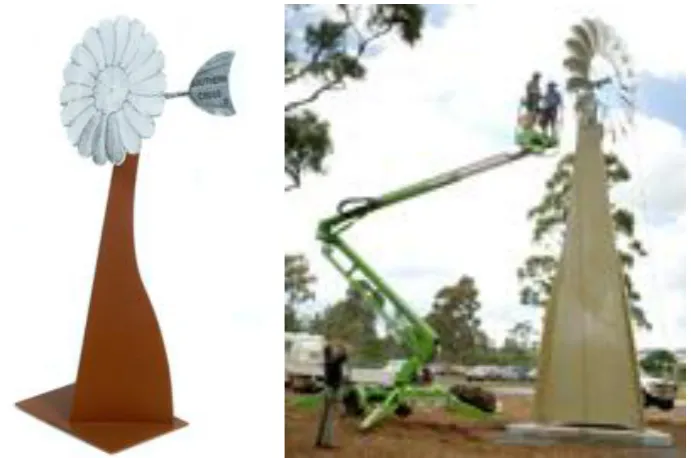
[image:1.595.179.408.363.537.2]During the 40th anniversary celebration of the University of Southern Queensland, an artistic concept was put to merge the Australian tradition of using windmills with the advanced usage of fibre composite materials. This sculpture represents bridging the old and the new technology in a project where staff members of the Faculty of Arts, the Centre of Excellence in Engineered Fibre Composites (CEEFC) of the Faculty of Engineering and Surveying along with a well experienced fibre composite manufacturing company got-together to successfully complete this project ( Figure 3).
In fibre composites, the cost of setting the manufacturing procedures is significant. Accordingly, this need has to be considered early in the design. In the case of the USQ windmill monument, a few alternatives were considered. The first is based on using pultrusions in lattice form with cladding system to meet the artistic concept. The second is based on using a combination of pultrusions and sandwich panel to form the tower. However, due to the manufacturing technology available within the selected fabricator, who specialises in boat and submarine structures, all-sandwich windmill structure was used to avoid high manufacturing costs. This decision was made at early stage of the design process with close coordination with the manufacturer.
2. Sandwich Structures
[image:2.595.108.491.70.268.2]The sandwich form of construction is a relatively new system where the main load-carrying faces (skins) are separated by a relatively weak core material. This structure characteristics include light-weight, high stiffness, and excellent absorption of mechanical and sound energy. The Second-World-War “Mosquito” aircraft is often referred to as the first major structure that incorporated sandwich panels. Sandwich structures started to gain popularity by the middle of the 20th century when different metallic faces and core materials were used for the construction of aircrafts and marine vessels. The development of high-strength, high-modulus, light-weight
Figure 2 Truman workshop and windmill tower during erection in SA, 1899 (Millicent National Trust Museum, Millicent, South Australia)
[image:2.595.127.473.312.541.2]fibres and new forms of core materials has opened a new horizon for sandwich structures where the structural properties can be fully adapted to the design requirements. In addition, the orthotropic nature of the composite materials, along with the flexibility in selecting the fibre types and architecture, can significantly increase the buckling capacity of the sandwich structure (Librescu and Hause, 2000).
During the 1950s, the US Forest Products Laboratory (USFPL) was the primary group in developing analysis and design methods for sandwich structures. Their effort led to publishing the military design handbook MIL-HDBK-23 (Anon, 1955) that was continuously updated until being cancelled in 1988. For many years, Allen (1969) and Plantema (1966) were the most popular references that provided simplified and practical approaches to the analysis and design of sandwich structures.
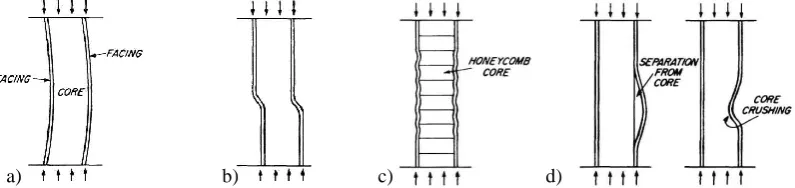
The behaviour of the sandwich structure is significantly affected by the properties of its components (skins and core). Four failure modes for sandwich structures (two global and two local) are presented in the MIL-HDBK-23 (Anon, 1955) and found in many references such as Vinson (1999), Fleck and Sridhar (2002), and Omar et al (2007). In addition to the overall buckling (Figure 4a), shear crimping failure (Figure 4b) is another form of general overall buckling in which the wavelength of the buckles is very small, because of the low core-shear modulus. The crimping of the sandwich occurs suddenly and usually causes the core to fail in shear at the crimp; it may also cause shear failure in the bond between the facing and the core. It is important to note that the critical skin stress, where core shear instability can occur, is independent of the panel dimensions. However, it is related to the core and skin properties and the boundary conditions (Vinson, 1999). If the core is of cellular structure, honeycomb, it is possible for the facings to buckle or dimple into the spaces between core walls or corrugations as shown in Figure 4c. Wrinkling is the fourth form of failure (Figure 4d). It can occur if the skin buckles inward or outward, depending on the flat-wise compressive strength of the core relative to the flat-wise tensile strength of the bond between the facing and the core. If the bond between the facing and the core is strong, facings can wrinkle and cause tension failure in the core. This simulates plate-on-elastic foundation. The wrinkling load depends upon the elasticity and strength of the foundation system, namely, the core and the bond between the facing and the core. Since the facing is never perfectly flat, the wrinkling load will also depend upon the initial eccentricity of the facing or original waviness (Allen, 1969).
For fibre composite skins, face plastic micro-buckling failure is a shear buckling instability of the face fibres due to large shear strains in the face matrix (Fleck, 1997). The shear yield strength of the composite and the initial fibre misalignment angle are the main factors controlling the micro-buckling compressive strength, Argon (1972) and Budiansky (1983). The compression strength is sensitive to the degree of imperfection (fibre waviness) and the fibre mis-alignment with the loading direction. For sandwich panels under compression, plastic micro-buckling of the skins is the most probable failure mode (Fleck and Sridhar, 2002). It occurs when the axial compressive stresses in the skins attains the plastic micro-buckling strength.
The most commonly used equations for sandwich panels subject to axial loads are presented in Appendix A for reference.
3. Structural System and Materials Used
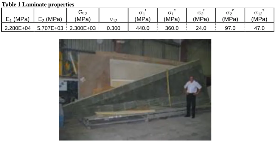
[image:3.595.99.497.529.623.2]The USQ windmill structure has few components. The tower is 7900mm high with a 2300mm base that has two wings extending 300mm, at the ground level. The two wings stoped mid-height of the tower that tapered to 400mm at the top, Figure 5. The tower structure was manufactured from double skins of glass/vinyl ester with 15mm closed-cell PVC foam R60 & H100 grades. The material properties used in the model to model each laminate ply is shown in Table 1, where tensile properties (t) were determined according to ISO 527-4/2/2(1993)
Figure 4 Modes of failure in sandwich panels under edge load - MIL-HDBK-23 (Anon, 1955)
in both the fibre direction (1) and the normal-to-fibre direction (2). Similarly, compression properties (c) were determined according to ISO 14126(1999). The shear properties (12) were determined according to the ISO 14129(1997). Double bias glass fibres were used with 800gsm weight. As most of the loads are transferred as axial forces at the tower corners, skins are reinforced at these areas. Flat panels were connected by using angles that were laminated then laid on the faces. The fibre architecture of the different components is shown in Figure 5 where the zero definition of the fibre architecture is along the centre of each face of the tower. At corners, to avoid the wrinkling failure and increase capacity of the sandwich panels, higher grade (H100) foam was used at corners, Figure 5.
Table 1 Laminate properties
E1 (MPa) E2 (MPa)
G12
(MPa) 12
1 t
(MPa)
1 c
(MPa)
2 t
(MPa)
2 c
(MPa)
12 s
(MPa)
2.280E+04 5.707E+03 2.300E+03 0.300 440.0 360.0 24.0 97.0 47.0
[image:4.595.69.551.180.503.2]Wings
Figure 5 Layout of the windmill and its connection details
Corner angles Sandwich panels
Top steel bracket
Corner angles
[image:4.595.68.530.518.756.2]The tower composite structure is connected to the foundations through steel brackets that are connected to the raft footing on three piers by using M20 Reo 502 ChemSet studs. The windmill gearbox was supported to the tower through top steel bracket with the mill shaft welded. At connection to steel brackets, solid laminates replaced the core foam.
4. Structural Analysis and Design Checking
Wind load calculations were based on the AS1170.2 assuming solid frontal area of the blades and the tower structure. This conservative approach was followed as there was no design specification for these types of structures found either in the design codes or the manufacturer specifications. In addition, equivalent gyroscopic moment was calculated and applied to tower assuming that blades are rotating at 5Hz.
Prior to commencing the structural analysis, the literature was surveyed for the FE modelling techniques established for sandwich structures. Vannucci et al (1998) conducted a comparison between the performance of some theories and FE models of sandwich plates and shells. Compared with Pagano (1970) for square and rectangular plates, they concluded that using discrete-shear quadrilateral elements, based on the theory of Mindlin-Reissner for the analysis of thick plates, provided the best response with results within 20% of the exact solution. Akfert (1994) used the commercial FE package (Abaqus) with a foam material model based on a volumetric hardening model as described by Gibson et al (1982) Maiti et al (1984), and Gibson et al (1997), with skins, adhesive layers and core materials modelled as plain strain two-dimensional continuum elements. Muc and Zuchara (2000) investigated the buckling and failure analysis of thin-walled composite sandwich plates. Their 2-D geometrical nonlinear formulation was found to correlate well with the 3-D FE analysis. Shell elements were used for the sandwich skins while 3-D solid elements were used to model the core. This approach was found to be quite effective for static and impact problems (Haug and Jamjian, 1996). Bazant and Beghini (2004), in using variational analysis and comparing them with standard FE model predictions, concluded that it is correct to simulate soft-core sandwich structures with the standard FE programs using Lagrangian updating algorithm.
Simplified FE model (using thick shell elements) can be used to predict the stress distributions in the tower. However, a more detailed model was used to investigate the stress levels at the skins, adhessive layers and core materials. This was essential in this project due limitations in to testing. Accordingly, Solid-Shell elements were used to model the tower. Thick shell elements were used for the skins and the corner angle, with the laminate properties specified in Table 1, while 3D solid elements were used to model the core material and the adhesive layers, assuming isotropic material properties, modulus of elasticity 42MPa, 90MPa & 2430MPa and Poisson’s ratio 0.10, 0.30 & 0.30 for the R60, H100 foams and adhesive layers respectively. This can be considered a reasonable assumption as both the adhesive layers and the core material will not be stressed to a level higher than their elastic limit.
ABQUS FE commercial package was used for the analysis. The FE model was built in parts that were then assembled to create the overall model, Figure 5. The individual parts were interconnected using tie (kinematic) constraints. Kinematic constraints were imposed by eliminating the degrees of freedom (DOF) at the dependent (slave) nodes and constraining them to the governing (master) nodes. A surface-based tie constraint was used in the FE model. This concept is useful for mesh refinement purposes. It allows rapid transitions in mesh density within the model (Hibbitt et al, 2004).
In checking the structure, the following were considered:
For the laminates, partial safty factors (EuroComp, Clarke, 1996) were assumes as m,1 m,2 = m,3 = 1.10 that totaled m = 2.00.
For the laminates, the Tsai-Wu failure index was used.
For the adhesive stresses, maximum stresses obtained from analysis are compared with the shear and tensile test values.
Stresses in the sandwich skins were limited by the different sandwich panel failure modes.
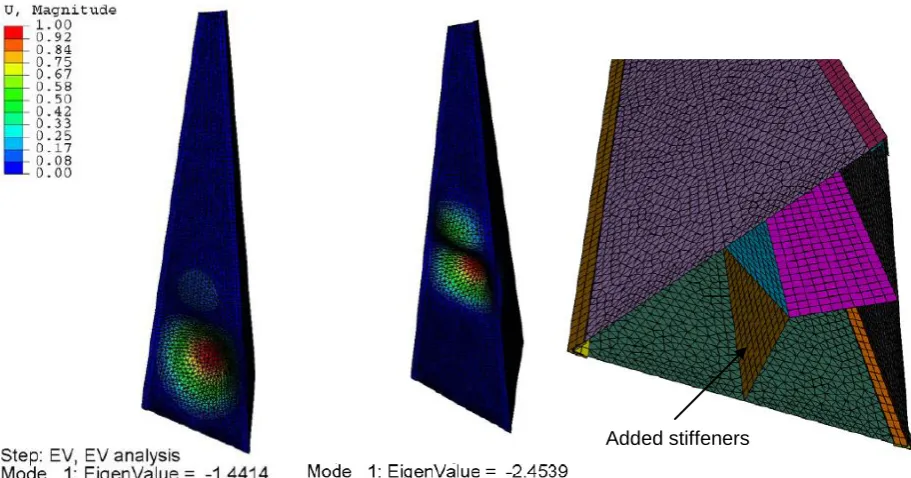
tower. This arrangement increased the eign value from 1.44 to 2.45 with a change in the buckling mode, Figure 7.
5. General Discussions of Using Fibre Composites as a Main Structural
System
Fibre composites are relatively new materials that have been developed since last century. They provide the designer greater flexibility in the choice of materials to be used, how to combine these materials and in which form. This flexibility is associated with challenges of delivering a safe structure with limitations on the availability of test data and understanding of the essential behavioural issues of the material and the structural system it is used for. As a consequence, the popularity of these materials in structures and acceptance among structural engineers is being affected. There are a few important considerations that need to be understood by designers working with these materials which can be highlighted as follows:
- In spite of being under development for many years, there is a lack of understanding of the mechanisms that lead to failure in composite materials. This is especially true for matrix or fibres under compression (Davila et al, 2005). This explains the generally poor predictions by most of the participants in the World-Wide Failure Exercise (WWFE). The current design practices place little or no reliance on the ability to predict the ultimate strength of the composite structure with any great accuracy. Failure theories are often used in the initial calculations to size the structure. Then experimental tests on coupons or structural elements are used to determine the global design allowables, which are usually less than 30% of the ultimate load (Soden et al, 1998). The issue addressed was the definition of failure. A designer would define failure as the point at which the structure ceases to fulfil its function. This definition is accordingly application-specific. It was concluded that the connection between events at the lamina level and the definitions of structural failure required by designers need to be established (Hinton and Soden, 1998).
- Tsai’s theory is one of the best available theories in predicting the failure of the laminate. It employs the interactive Tsai-Wu failure criterion which is one of the best-known and mathematically satisfying theories (Hinton et al, 2002). However, like many of the other theories, this theory is linear-elastic and it can not predict the large non-linear strains observed in tests with high lamina shear.
- The orthotropic nature of the composites makes them different from other commonly used construction materials. Accordingly, this effect needs to be considered while designing with these materials.
[image:6.595.87.543.119.358.2]- Transverse shear properties of the composite are another important consideration that needs to be incorporated in the FE analysis.
Figure 7 Buckling mode shapes and stiffener layout
- For sandwich structures, the core properties, especially shear modulus, significantly affects the failure mode and capacities.
- Due to its sudden brittle nature, overall buckling of sandwich panels need to be carefully considered in any of its analysis.
- As presented in Appendix, there are still differences in opinion in predicting the capacity of some of the failure modes of sandwich columns. Accordingly, this need to be considered related to the problem in hand.
- It is important to allow smooth transition of stresses at the joints. This may necessitate allow larger curvatures and laminate transition zones. In addition, manufacturing tolerances should be considered. These issues should be recognised by the designer at early stage of his/her design.
6. Concluding Remarks
Fibre composites in civil engineering applications have huge potential. However, there is a grate challenge for the structural designer when there are no specific design standards and familiarity with the behaviour of such new materials. This is further affected by the limitations of the manufacturing technology possessed by the contractor.
This paper highlights how such issues have been overcome by discussing the case study of a windmill monument structure. By forming an alliance with the designer, client and the manufacturer, working towards the best outcome for the project within the constraints had led to the successful completion of the structure. It is believed such model could be very effective in gaining acceptance of innovative materials in civil infrastructure.
Other challenges faced by the structural designer in such cases are the understanding of the behaviour of the materials, its failure mode and adopting available design guidelines to the local needs. This also emphasise the need to train structural engineers in fibre composites and the development of relevant design standards/guidelines in Australia. When these are achieved, the fibre composites will become competitive with the traditional construction materials and it would be possible to harness its potential in civil infrastructure.
7. Appendix - Predicting Sandwich Panels Capacity under Compressive
Loads
Few sandwich column buckling formulae have been developed and reported. Allen (1969) proposed two formulae, one each for thin and thick face sheets. Allen’s formulae were based on Engesser theory. For thick faces, the formula uses the advanced sandwich theory, where faces bend locally in order to follow the shear deformation of the core. Thus the additional shear deflections of the core are reduced by the local bending stiffness of the faces (Allen and Feng, 1997). In this method, the Euler critical load is divided by the correction factor (r, Eq.1) to obtain the critical load with shear correction.
EI
EI
D
l
EI
EI
EI
D
l
EI
EI
EI
r
s Q s Q s 2 2 2 21
1
1
1
(1)Core shear instability can occur by increasing the section bending stiffness or reducing the core shear stiffness. The critical skin stress for shear instability can be predicted by Eq.2 (Mamalis et al., 2005).
c cr
G
ht
h
t
2
)
(
2
(2)Assuming uniform stress distributions, the micro-buckling capacity of the sandwich column is given by Eq.3 (Fleck and Sridhar, 2002).
bt
P
mb mb2
(3) Where,EI: Effective bending stiffness of the cross-section Ec, Gc: modulus of elasticity and shear modulus of core
material
Es: modulus of elasticity of skins in the loading direction
l: Effective column height a=t+(h/2), c=(t+h)/2 & d=h/2 EIs=Esbt
3
/6 & DQ=4bc 2
Gc/h
Where,
Pmb: axial load for micro-buckling
For isotropic faces and core materials, the critical skin stress where faces start to wrinkle can be described by Eq.4 (Hoff and Mautner, 1945) with disagreement between different researchers about the value of the constant C that ranged from 0.50 to 0.90 (Vinson, 1999). For orthotropic cores, Vonach and Rammerstorfer (2000) suggested Eq.5, with C=0.85. Gdoutos et al (2003) stated that the difference in the predicted critical stress, between using Eq.4 (assuming isotropic core material) and Eq.5, is less than 5% for the Ecx/Ecz ratio of 10-100%. However, for highly orthotropic core properties, the critical stress will be reduced significantly.
1/3c c s
cr
C
E
E
G
(4)
2
1/3)
(
thicks
cr
C
E
k
(5)Where, 4 1 1 3 2 4 1 3 2 4
)
(
cz cx cz cz cx zx c thickE
E
E
E
E
X
X
X
X
k
; 2 2 2 1 1 3 2 23
cxzD
cD
cX
; 2 2 2 1 1 3 2 14
cxzD
cD
cX
;1
2 1
;
2
2
1
;13 3 1 c c c
D
D
D
; cx cE
D
1
;cxz cxz cx cxz cx c
G
E
G
E
D
2
2
13
; andD
c3
E
cz.8. References
Akfert, A. (1994). Finite element analysis of composite sandwich beams and plates, MSc, University of Manchester, Manchester.
Allen, H. G. (1969). Analysis and design of structural sandwich panels, Pergamon Press, Oxford.
Allen, H. G., and Feng, Z. (1997). Classification of structural sandwich panel behaviour. Mechanics of Sandwich Structures, Proceeding of the EUROMECH 360 Colloquium, A. Vautrin, ed., Kluwer Academic Publishers, Saint-Etienne, France, 1-12.
Australian Windmills Homepage. http://au.geocities.com/ozwindmills/.
Anon. (1955). Materials, properties and design criteria Part II, sandwich construction for aircraft. MIL-HDBK-23, Department of the Air Force Research and Development, USA.
Argon, A. S. (1972). Fracture of composites. Treatise on Material Science and Technology, Academic Press, New York, 79-114.
American Society for Testing and Materials. (2000). ASTM C393-00: Standard Test Method for Core Shear Properties of Sandwich Constructions by Beam Flexure.
Bazant, Z. P. (1971). A correlation study of incremental deformations and stability of continuous bodies. ASME Journal of Applied Mechanics, 38, 919-928.
Bazant, Z. P. (2003). Shear buckling of sandwich, fiber composite and lattice columns, bearings, and helical springs: paradox resolved. ASME Journal of Applied Mechanics, 70, 75-83.
Bazant, Z. P., and Beghini, A. (2004). Sandwich buckling formulas and applicability of standard computational algorithm for finite strain. Composites Pt B, 35, 573-581.
Budiansky, B. (1983). Micromechanics. Computers and Structures, 16(1-4), 3-12.
Clarke, J. L. (1996). Structural design of polymer composites - Eurocomp. E & FN Spon, London.
Davila, C. G., Camanho, P. P., and Rose, C. A. (2005). Failure criteria for FRP laminates. Journal of Composite Materials, 39(4), 323-345.
EPA. Environmental Protection Agency Homepage. http://www.epa.qld.gov.au/cultural_heritage.
Fleck, N. A. (1997). Compressive failure of fibre composites. Advances in Applied Mechanics, 33, 43-117.
Fleck, N. A., and Sridhar, I. (2002). End compression of sandwich columns. Composites Pt A, 33, 353-359.
Gdoutos, E. E., Daniel, I. M., and Wang, K.-A. (2003). Compression facing wrinkling of composite sandwich structures. Mechanics of Materials, 35, 511-522.
Gibson, L. J., and Ashby, M. F. (1997). Cellular solids: structure & properties, Cambridge University Press, Cambridge.
Gibson, L. J., Ashby, M. F., Schajer, G. S., and Robertson, C. I. (1982). The mechanics of two-dimensional cellular materials. Proceedings of the Royal Society, London, 25–42.
Hassan, A. Y. and Hill, D. R. (1986). Islamic Technology: An illustrated history. Cambridge University Press, ISBN 0-521-42239-6.
Hibbitt, K. S. I. (2004). ABAQUS Analysis user's manual, Pawtucket, USA.
Hinton, M. J., Kaddour, A. S., and Soden, P. D. (2002). A comparison of the predictive capabilities of current failure theories for composite laminates judged against experimental evidence. Composites Science and Technology, 62, 1725-1797.
Hinton, M. J., and Soden, P. D. (1998). Predicting failure in composite laminates: the background to the exercise. Composites Science and Technology, 58, 1001-1010.
Hoff, N. J., and Mautber, S. E. (1945). The buckling of sandwich type panels. Journal of Aeronautical Sciences, 12(3), 285-297.
Huang, H., and Kardomateas, G. A. (2002). Buckling and initial postbuckling behavior of sandwich beams including transverse shear. AIAA Journal, 40(11), 2331-2335.
International Standard. (1993). ISO 527-4: Plastics - Determination of tensile properties.
International Standard. (1999). ISO 14126: Fibre-reinforced plastic composites - Determination of compressive properties in the in-plane direction.
Librescu, L., and Hause, T. (2000). Recent developments in the modeling and behavior of advanced sandwich constructions: a survey. Composite Structures, 48, 1-17.
Mamalis, A. G., Manolakos, D. E., Ioannidis, M. B., and Papapostolou, D. P. (2005). On the crushing response of composite sandwich panels subjected to edgewise compression: experimental. Composite Structures, 71, 246-257.
Maiti, S. K., Gibson, L. J., and Ashby, M. F. (1984). Deformation and energy absorption diagrams for cellular solids. Acta Metallurgica, 32(11), 1963–1975.
Marguerre, K. (1944). The optimum buckling load of a flexibly supported plate composed of two sheets joined by a light weight filler, when under longitudinal compression. ZWB UM 1360/2, Deutsche
Vierteljahrsschrist für Literalurwissenschaft und Giests Geschichte, D V L.
Muc, A., and Zuchara, P. (2000). Buckling and failure analysis of FRP faced sandwich plates. Composite Structures, 48, 145-150.
Omar, T. (2008). Multi-pultrusion fibre composite truss systems for deployable shelters, PhD, University of Southern Queensland, Toowoomba, Queensland, Australia.
Omar, T., Aravinthan, T., and Van Erp, G. (2007). "Behaviour of sandwich columns under edgewise
compression loading." Asia-Pacific Conference on FRP in Structures (APFIS 2007), Hong Kong, China.
Pagano, N. J. (1970). Exact solutions for rectangular bidirectional composites and sandwich plates. Journal of Composite Materials, 4, 20-34.
Southern Queensland, Toowoomba, Queensland.
Rheinfrank, G. B., and Norman, W. A. (1944). Molded glass fiber sandwich fuselage for BT-15 airplane. Army Air Corps Technical Report No 5159, USA.
Soden, P. D., Hinton, M. J., and Kaddour, A. S. (1998). Comparison of the predictive capabilities of current failure theories for composite laminates. Composites Science and Technology, 58, 1225-1254.
Vannucci, P., Aivazzadeh, S., and Verchery, G. (1998). A comparative analysis of some theories and finite elements for sandwich plates and shells. Mechanics of sandwich structures, A. Vautrin, ed., Kluwer Academic Publishers, Saint-Etienne, 45-52.
Vinson, J. R. (1999). The behavior of sandwich structures of isotropic and composite materials, Technomic Publishing Company, Lancaster, Pennsylvania.
Vonach, W. K., and Rammerstorfer, F. (2000). The effect of in-plane core stiffness on the wrinkling behaviour of thick sandwiches. Acta Metallurgica, 141, 1-10.
The Windmill Journal. Homepage. http://users.chariot.net.au/~hdpump/links.html.
Wikipedia Homepage. http://en.wikipedia.org/wiki/Windmill