IAC-10-A6.4.13
ORBITAL DEBRIS REMOVAL WITH SOLAR CONCENTRATORS
M. Vasile
Space Advanced Research Team, University of Glasgow, United Kingdom, m.vasile@aero.gla.ac.uk
C. Maddock*, C. Saunders†
In 1993 solar concentrators were first proposed to deflect asteroids away from a collision course with the Earth. The original concept was expanded by the authors, and proved to be effective and technologically feasible. One way to deflect the asteroid is to produce a slow decay of its orbit by inducing a thrust via concentrated solar light. Two mechanisms have been investigated: the sublimation of the surface of the asteroid to generate a jet of gas and the induced thrust by light pressure and enhanced Yarkovsky effect. If the concentrators are reduced in size, a similar concept can be adopted to remove orbital debris and inert satellites. In this paper, we present an orbital debris removal system based on concentrated solar light. We will show how enhanced solar pressure, generated by a formation of solar concentrators, can be used to accelerate the decay of small inert objects orbiting the Earth. A set of modified proximal motion equations is proposed to describe the relative dynamics of the solar concentrators with respect to the target piece of debris. The paper will provide an analysis of the cost of the optimal control of the concentrators during the deflection of the debris and a system engineering analysis. In particular, we will show that the concentrator acts as an active solar sail while not deflecting, and as a hybrid solar sail (i.e. the orbit is maintained with an auxiliary low-thrust engine) while deflecting the debris. The results will show that objects with even a small area-to-mass ratio (down to 0.01) can be brought from an 800 km to a 200 km altitude orbit in few hundred days of constant operation. The paper will discuss also the possibility to vaporize some small size targets with high power solar pumped laser.
I. INTRODUCTION
Over the past decade, numerous techniques for altering the orbital course of an object in space have been studies, within the field of asteroid deflection. One such method proposes to use a solar concentrator to focus a small beam of light, with a high power density, onto the surface of an object, thereby inducing a sublimation of the surface material and creating a jet of debris. This in turn produces a low thrust which alters the course of the object. For asteroids, using solar-powered collimating lasers onboard a fleet of satellites, the required input power is on the order of MW, with a reflector diameter of 20 m. If instead of sublimating the material, the pressure induced by a combination of absorbed, reflected and emitted light is used to create a thrust, the reflector diameter is around 60 m.*†
Using the asteroid Apophis (MN2004) as an example, the area-to-mass ratio (AMR) is 3.26×10⁻¹⁰ m2/kg. If the onboard reflector system is reduced in size, a similar concept can be adopted to remove orbital debris and inert satellites an AMR in the range of 0.0001–1 m2/kg. The following will study the use enhanced solar pressure, generated by a spacecraft formation of solar concentrators, to accelerate the decay of inert objects in Low Earth Orbit (LEO), and remove
*
Space Advanced Research Team, University of Glasgow, United Kingdom, c.maddock@aero.gla.ac.uk
†
Space System Engineering, QinetiQ, Farnborough, United Kingdom, cjsaunders@qinetiq.com
objects from the Geostationary Orbit (GEO), GPS orbit or Geostationary Transfer Orbit (GTO).
A set of modified proximal motion equations is used to describe the relative dynamics of the solar concentrators (or satellites) with respect to the target piece of debris. The following will provide an analysis of the cost of the optimal control of the concentrators during the deflection of the debris and a system engineering analysis. In particular, we will show that the concentrator acts as an active solar sail while not deflecting, and as a hybrid solar sail (i.e., the orbit is maintained with an auxiliary low-thrust engine) while deflecting the debris. The results show that objects with even a small area-to-mass ratio (down to 0.01) can be brought from an 800 km to a 200 km altitude orbit in few hundred days of constant operation. The paper will also discuss the possibility to vaporize some small size targets with a high power solar pumped laser.
I.I. Asteroid deflection method
sublimation, by inducing a low thrust by light pressure and enhanced Yarkovsky effect.4,5
In the case of sublimation, two methods were investigated in the study: i) the direct reflection of solar light onto the surface of the asteroid; ii) the use of solar- or electrically-pumped lasers to generate the required sublimation process.
The first concept has a very high system efficiency as nearly 90% of the sunlight is expected to be focused onto the surface of the asteroid. However, the physical limit on the focusing and collimation of sunlight requires the spacecraft to operate in close proximity t to the asteroid, with a consequent fast deterioration of the optics. The second laser concept has a lower system efficiency (about 25% of the input solar light is translated into laser light, considering 30% efficiency of
the solar cells and an 85% efficiency of the semiconductor laser) but allows for a very high enhancement factor even at far distances from the target. The result is that the laser concept could provide significant deflection even with moderate size spacecraft and reflectors. In the study, semiconductor, electrically pumped lasers were preferred to directly pumped lasers as they offer a higher overall efficiency. Furthermore the development of solar cells and semiconductor laser (electrically pumped) is expected to progress faster, from a technology readiness level, than light pumped lasers due to the numerous cross over applications in other fields. Given the constant progress in the efficiency of solar cells, it is expected that solar arrays are going to soon reach their theoretical limit, bringing the overall efficiency of the laser system to about 40%.
In the case of the direct focusing of the solar light, the sublimation ceases once the mirrors are contaminated. However it was demonstrated that even if the sublimation process is not started (i.e., the surface temperature is not high enough), the asteroid can still be deflected by simply enhancing the effect of the solar pressure and the Yarkovsky effect.4 An advantage is because there is no sublimation, and hence no debris plume and contamination, the mirrors/optics do not deteriorate; furthermore they can operate at farther distances.
In order to keep the size of the reflector and of the spacecraft down, it is proposed to have multiple spacecraft of a small size rather than a single one of large size. The advantage of using multiple small reflectors is that the satellites will remain more agile and easier to deploy and control. Furthermore, the cross section area of each satellite will be smaller thus requiring smaller electric propulsion engines to control the orbits and counteract solar pressure and drag during de-orbiting and altitude rising.
II. DEBRIS POPULATION ANALYSIS To a certain degree, space debris exists in all orbital regions around the Earth, although it is primarily concentrated in those parts of orbital space that are most heavily utilized by operational spacecraft. Of the ~14200 objects currently tracked from the ground by space surveillance sensors, ~90% are ‘debris objects’: either non-operational spacecraft, fragments from collisions or explosions, expended rocket bodies, mission fragments, etc.
In 2010, Musci et al.6 demonstrated, from observations, that in GEO there is a consistent population of orbital debris with high AMR (>1 m2/kg) and confirmed the simulations of Liou et al.7 and Anselmo et al.8, who showed that solar pressure causes a substantial change in the orbital elements of high (a)
[image:2.595.70.293.114.496.2](b)
AMR bodies in GEO. Anselmo et al. also proposed a similar analysis for high AMR bodies in GPS orbits.
Despite the change in orbital elements demonstrated by Musci and Anselmo, high AMR bodies in GEO and MEO do not decay and instead continually intersect, or remain in close proximity, to their original orbit, especially if the AMR is below 5 m2/kg. High AMR bodies could be easily moved out of GEO and transferred to the graveyard orbit by the use of solar concentrators that can properly direct the solar pressure. Alternatively, their perigee could be progressively lowered until an intersection with the Earth atmosphere by acting at the apogee with a constant solar pressure. This approach could also work well for any debris in the GTO, or any highly elliptical orbit. The use of enhanced and controlled solar light is not limited to high AMR bodies in GEO: a constant application of enhanced solar pressure to bodies with an AMR of 0.01 m2/kg can significantly accelerate their decay.
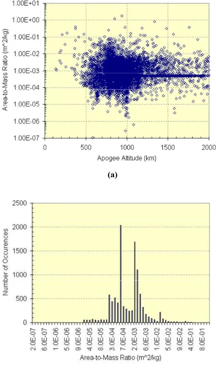
A key parameter for this analysis is the debris area-to-mass ratio which directly influences the effectiveness of the momentum transfer of the lased photons. Unfortunately, getting an accurate estimate of the AMR for a piece of space debris is non-trivial. All surveillance missions of the orbital population are conducted by remotely sensing therefore accurate estimates of both the object’s cross-sectional area and its mass are extremely difficult. In the USAF TLE representation of the object, there is no direct measure of the AMR. Instead, there is a B* value, which is a modified ballistic coefficient containing information on the objects drag coefficient as well as other parameters. It is further complicated by the fact, that often in the orbit determination process, the B* value is used as a free parameter to ‘soak up’ the effects of mis-modeled physical forces (e.g., incorrect gravity models). Hence the published B* may not be a true representation of the real AMR. It is however, generally a reasonably good estimate (as force models are generally well developed), and is used here in lieu of any other data. Using the conversion outlined by Vallado,9 we can convert to a true ballistic coefficient, which is the AMR value including a value for the drag coefficient. Determining the drag coefficient is also very difficult (it is highly dependent on object shape and orientation), but assuming a constant value of 2.5, reveals the AMR for all the debris objects in LEO. This data is shown in Fig. 1.
It should be noted that, as discussed above, the B* is an output from the orbit determination process. It is therefore a variable parameter that actually depends on the state of the atmosphere at the time of the determination. The density of the upper atmosphere is itself correlated with solar activity, and there at times such as now when the sun has just passed solar minimum, the reported B* and AMR values from TLE
are likely to be lower than might be expected. Conversely at periods of solar maximum, the B* and AMR values from TLE are likely to be higher than might be expected. Of course, the values in the TLE are not the actual AMR of the object (this is fixed by its physical properties), but are its reported value from the orbit determination process. As a result, the values are probably an underestimate of the actual AMR of the object if this was to be determined purely from its area and mass.
For the majority of objects in the TLE data, the AMR ranges from ~0.05 to ~0.0002 m2/kg, with the median value being ~0.001 m2/kg This corresponds reasonably well to published data on the fragmentation and break-up of satellites in LEO, as well as for intact satellites that are non-operational, and hence can be considered as debris. The data presented by Anz-Meador and Potter10 shows the AMR values for a set of LEO fragmentation events, ranging from ~1 down to 0.001 m2/kg. Another paper by Pardini et al.11 in 2009 considered the deliberate shoot-down of the decaying satellite USA-193. Based on an analysis of it decay rate, the authors estimated an area-to-mass ratio of ~0.0044 m2/kg for the intact satellite, assuming a value of 2.5 for the drag coefficient.
For debris objects in GEO, the situation is more complicated because in GEO, there is obviously no atmospheric drag, and the AMR must then be determined through the orbit determination process via the effects of solar radiation pressure on the object. Furthermore because GEO altitudes are so high compared to LEO, typically only optical telescopes are used to survey GEO, and as a consequence there is a typical minimum size limit of 1 m – 0.5 m on the size of detectable objects, and such there is a ‘lack’ of debris objects in the USAF orbital catalogue for GEO. Even for those GEO or near-GEO objects characterized as debris or old rocket bodies in the TLE catalogue, the B* value is given as 0.0005 for all the objects, indicating that this has simply been fixed at an arbitrary value.
In GEO, a particular problem is non-operational spacecraft that are either left in GEO at the end of their mission, or else are not de-orbited to a sufficient altitude above the GEO ring. Because of the particular gravitational dynamics of the GEO ring, a satellite left in or near GEO will librate between longitudinal boundary values indefinitely, thereby causing a collision (and potentially radio interference) risk to other satellites. This has occurred recently, with the on-orbit failure of the Galaxy 15 satellite in April 2010. This is now a large piece of debris drifting around GEO, and will continue to do so for thousands of years unless control of the satellite can be regained, or it can be removed from GEO.
Tenerife.12 This has uncovered a new population of debris with very high area-to-mass relationships (>20 m2/kg). This is thought to be pieces of multi-layer insulation that has become detached from spacecraft. This debris poses an interesting challenge, as due to its very high AMR values, the eccentricity of its orbit can change from near zero to over 0.5 in ~1 year, driven by solar radiation perturbations. This results in very large variations in the perigee and apogee altitudes of the object.
There have also been explosions of rocket bodies in GEO, with two events confirmed and potentially evidence for over 10 such events13. Assuming the breakup models developed for LEO and other regions to be the same in GEO (there is no evidence to suggest to the contrary) then this would produce debris with the same basic spread of AMR values as for the LEO cases. Debris from explosions such as this can rapidly spread throughout the GEO ring, posing a collision risk for all
GEO objects, not just those near the longitude where the fragmentation occurred.14
It can be seen that potentially the GEO environment contains debris that spans several orders of magnitude of AMR ratios. In terms of risk to other users of GEO, the major target would seem to be larger intact (but non-operational) GEO vehicles or other large bodies such upper stages from launch vehicles. This is for two reasons:
1) Larger objects have a larger collision cross section (i.e. are at a greater risk of suffering an impact) and hence subsequently producing further debris fragments which will in turn pose a risk to other objects. 2) Larger objects generally have more mass, and hence if a collision does occur more massive fragments could be produced and these would again then pose a risk to other objects.
II.I. Debris orbit characteristics
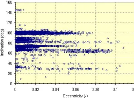
Fig. 2 shows the perigee and apogee altitudes of debris objects in LEO (here assumed to be < 2000 km altitude), while Fig. 3 shows the mapping of the eccentricity and inclination. The data was collected from the Two-Line Element (TLE) catalogue (as of June 2010) from the United States Air Force, and then filtered for those objects identified as either debris (‘DEB’) or rocket bodies (‘R/B’).
[image:4.595.68.288.109.277.2]As can be seen, most objects are in circular or near circular orbits. There is a significant population in slightly eccentric orbits; which has implications for any system design. It can be seen that there are several clusters of ‘popular’ inclinations. The main grouping is centered on 100°. This corresponds to objects in slightly retrograde orbits that are sun-synchronous or near-sun synchronous. This region is popular with remote sensing satellites, hence the large preponderance of debris in this region. There are other clusters around 80°–85° and also around ~65°, the later is probably associated with missions flying at or near the so-called ‘critical inclination’ of 63.4°, where the argument of perigee does not rotate (i.e., frozen orbits). There is a wide range of operational altitudes at all inclinations. Given the possibility of a cascading effect in LEO, whereby a hypervelocity collision occurs creating a cloud of new debris fragments, which in turn can collide with other objects creating further fragments and so on, it seems sensible to envisage that an active debris removal system such as the one proposed here, should be focused around these high density regions. In particular the large concentration of objects near the sun-synchronous inclinations should be considered a priority, as this is a highly utilized resource for many remote sensing, mapping and earth observation missions.
Fig. 2. Perigee versus apogee altitudes for debris in LEO.
[image:4.595.70.295.316.481.2]II.II. Debris physical characteristics
In terms of material type, debris can essentially be from any of the materials that were used to construct the original source that produced the debris. For larger objects such as non-operational spacecraft or rocket bodies then the material type will be construction material of the spacecraft. For this approach, the important material is that on the exterior of the vehicle, as this obviously affects the reflectivity of the object, and as such also effects the momentum imparted to the object via the solar concentrators.
For debris that has been produced via collisions or explosions, then the material type could theoretically be any of the materials used to construct the progenitor of the debris. Typically this might include metals such as aluminum and titanium, carbon fibre and other composites, glasses used on solar cells, and materials such as mylar and multi-layer insulation. Another important factor is that many spacecraft exterior surfaces are painted or covered in specific materials for thermal control purposes. This may include colored paints, second surface mirrors and various types of tapes (e.g. Kapton). These can change the reflectivity and absorptivity of the debris object (compared to its nominal value), and furthermore can change with time, as ‘space weathering’ (e.g. effects of solar ultra violet radiation) can darken the materials and change their optical properties. Furthermore, objects in low perigee orbits that spend a significant amount of time undergoing atmospheric interactions, can have their physical properties changed. This can result in the object becoming more diffusely reflective15.
III. MODEL DESCRIPTIONS
The operational concepts for debris in LEO and GEO are, respectively, depicted in Fig. 4 and Fig. 5. The reflector is effectively a hybrid solar sail. The light of the Sun is reflected on a secondary directional mirror and from there onto the piece of debris. The reflector needs to be controlled in close proximity to the piece of debris (few meters) to achieve the desired enhancement factor.
Note that the term enhancement factor here refers to the ratio between the cumulative effect of all the beams of light projected onto the target and the normal light pressure that the target would experience if directly exposed to the Sun. Therefore, if a single concentrator (i.e., spacecraft) can achieve an enhancement factor of 10, with the total required system enhancement factor of 100, then 10 solar concentrators will be needed to operate in the proximity of the piece of debris.
III.I. Solar pressure model
The light pressure model is similar to the one proposed by Pardini and Anselmo7, however we consider the
contribution of absorbed and reflected light separately. The total acceleration due to light pressure is:
(
)
2
2 (1 )
LP reflect absorb
p1AU r
a a a
S A
C m r
νη
λ α α
= +
= − +
(1)
where A/m is the AMR, α is the absorptivity of the surface material, Cr is the enhancement factor, λ is a
scattering factor that account for reflections in every possible direction over a hemisphere, Sp1AU is the solar
pressure at 1 AU (S0/c ≈ 4.562×10⁻⁶ kg/m·s), r is the
distance from the Sun, η is the efficiency of the reflector and ν is a Boolean variable that has a value of 1 when the reflector is in sunlight, and 0 when is not. The acceleration aLP is assumed to be in the opposite
[image:5.595.309.525.300.473.2]direction to the velocity of the debris.
Fig. 4. Operational concept for solar reflectors in LEO.
Fig. 5. Operational concept for solar reflectors in GEO.
III.II. Laser sublimation model
A first understanding of how the laser ablation system works can be obtained from an adaptation of the model presented in papers by Vasile et al.4,16,17 The amount of sublimated mass mexp is a function of the input power
Pin per unit area, which depends on the efficiency of the
laser, the thermal power that is dissipated through radiation Qrad and conduction Qcond, and the sublimation
[image:5.595.317.527.517.583.2](
)
1
exp
in rad cond
v
dm
P Q Q
dt =E − − (2)
Note, that the minimum required power for Pin is the
one that allows a sublimation of the material.
The average velocity v of the gas can be calculated by using the Maxwell distribution for particles of an ideal gas. The gas velocity is dictated by the sublimation temperature Ts, the Boltzman constant k
and the molar mass Mm:
8 s
m
kT v
M π
= (3)
Given the velocity of the particles and the rate of expelled mass we can compute the force acting on the asteroid. The force, or thrust, acting on the piece of debris Tsubl due to the sublimation process can be
calculated by dividing the thrust produced by the evaporation of the surface material corrected with a scattering factor Ssc accounting for the plume
dispersion:
subl sc exp
T
=
S v m
ɺ
(4)This model assumes that the material on the surface of the debris is sublimated, i.e., converted directly from solid to high temperature vapor (excluding any debris fragments). The enthalpy and sublimation temperature values are taken based on the boiling point in a vacuum of the specific material of the debris.
From literature on photoablation18 however, the laser is more likely to ionize the surface material thereby producing hot plasma. The thrust in this case is a function of the momentum coupling coefficient Cm.
For pulsed lasers, Cm is defined as the ratio of the
momentum produced (m∆v) to the laser pulse energy (EL); for continuous lasers, it is the ratio of thrust to
incident power,
(
0)
m plas m SA L C d
L L
m v T
C T C S A
E P η ε α
∆
= = → = (5)
where S0 is the solar flux density (W/m2) at 1 AU (this can be scaled using the inverse square of the Sun-satellite distance), α is the absorptivity of the debris, ηL
is the laser efficiency, εC is the cell efficiency and ASA is
the surface area of the solar arrays. Experimental results show that a momentum coupling factor Cm between 10
and 18 µN/W can be obtained for various materials with an Isp of 650-2245 s.
Assuming a constant thrust and a circular orbit (e = 0), the de-orbiting time can be estimated from the integration of the variation of the semi-major axis da/dt in Eq. (7),
0 0
0
exp
sp
sp
m I g a
t I g
T µ
≈
(6)
where a is the semi-major axis, µ is the gravitational constant, m0 is the initial or unsublimated mass of the
debris, g0 is gravitational acceleration in a vacuum and
Isp is the specific impulse. Fig. 6 shows various decay
times and amount of ablated material for different AMRs. If the piece of debris is not homogenous, e.g., an upper stage, the laser will target specific areas on its surface.
As an example, we can consider an aluminum plate with emissivity of 0.035. The sublimation enthalpy Ev is
10 MJ/kg, the material density 2700 kg/m3, the sublimation temperature 2792 K, the heat capacity 896 J/kg/K and the conductivity 156 W/m/K. If the plate is not connected to a radiator and is slowly rotating, the minimum power per unit area can be estimated to be 27700 kW/m2. If the laser provides 10% more than the minimum power per unit area, i.e., 30470 kW/m2, the mass flow is 0.25 kg/s/m2. The speed of the gas at 279 K, assuming a molar mass of 27 g/mol, is 1479.2 m/s which yields a force of about 235 N/m2. If we assume that the spacecraft is equipped with a solar array delivering 10 kW, the laser system has an efficiency of 30% and the absorptivity of the material is Fig. 6. Decay time (and ablated material) as a function of
[image:6.595.310.524.101.457.2]0.3, then the size of the illuminated spot is 3×10⁵ m2 with a resulting thrust of 7 mN and a mass flow of 7.5×10⁻⁶ kg/s. For a 1000 kg spacecraft, the acceleration is 7×10⁻⁶ m/s2. If the laser is applied continuously, the time to decay from an 800 km orbit down to a 200 km orbit would require 549 days.
Given the flow rate, this would translate into 356 kg of material, which represents a limit for this concept because the speed of the gas depends on the sublimation temperature; hence this system would be equivalent to rocket engine with an Isp limited by the sublimation
point. Because the thrust level can only be changed by increasing the flow rate an accelerated decay will not reduce the mass of ablated material. In other words, the fraction of ablated material will remain almost constant for a variation of the initial mass of the debris or power of the laser.
Therefore, as for spacecraft propulsion systems, the operational concept for the laser ablation system has to be mass efficient. On the other hand, experimental results on the achievable coupling coefficient demonstrated that an Isp of 2245 s can be obtained for
aluminum with a coupling coefficient of 36 µN/W. In this case a 1000 kg piece of debris can be brought from 800 km to 200 km in 118 days with a total of 15 kg of ablated mass. Therefore, the sublimation in vapor case in Eq. (4) underestimates the performance as it considers the temperature of evaporation and not the one of ionization. The actual energy transferred to the expelled gas can be higher with a resulting higher gas speed and total impulse.
The main issue here is that the sublimation of multilayered or inhomogeneous materials can cause the generation of undesired splinters. Furthermore, the sublimated material could potentially re-aggregate. Thus, not all the parts of an inactive satellite can be used to generate a thrust. In addition there are political issues related to the use of high power lasers in space. Similar issues prevented the implementation of ground laser systems like the one proposed in the Orion program.
III.III. Orbital Dynamics
To alter a satellite’s orbit, the added acceleration induced by the solar concentrators can be used in conjunction with the Gauss non-singular planetary equations19 below and integrated until the altitude (either the perigee, in the case of LEO, or the radial distance from the Earth, in the case of GEO) reaches a given threshold.
2
2
t
da a v u dt = µ
(
)
2 cos sin
t n
e f
de r f
u u
dt v av
+ = − cos h di r u dt h θ = (7) sin sin h d r u dt h i
θ
Ω =
c
2 sin 2 cos sin os
sin
t n h
d f ae r f r
u u u
dt ev
i
aev h i
ω= + + − θ
2
2 sin 2 cos
t n
df h f ae r f
u u
dt r ev aev
+
= − −
where [ut, un, uh] is the disturbing acceleration vector in
the tangential-normal coordinates (in this case equal to
aLP), [a, e, i, Ω, ω, f] are the Keplerian orbital elements
with θ = f + ω, h is the angular momentum and the radial distance r and the velocity v relative to the Sun are,
(
2)
1 2
1 cos
a e
r v
e f r a
µ µ
−
= = −
+
where µ is the gravitation constant of the Sun.
III.III.IDebris proximity
The formation of solar concentrators will have to fly in close proximity to the piece of debris. The proximal motion dynamics will be described in a local, rotating reference frame (Hill frame) centered on a virtual ‘chief spacecraft’. The motion of both the reflectors and debris will be described with respect to the virtual chief spacecraft. The forces acting on the reflector during the removal operations are mainly gravity and solar pressure. Gravity comprises the gravity field of the Earth and third body effects, which are particularly relevant in GEO. The solar pressure instead depends on the specific configuration. For the operational concept in Fig. 5, the solar pressure will generate the forces represented in Fig. 7 based on the normal vector of the reflectors.
The dynamics of both the reflector and the debris can be expressed using the same general set of proximal motion equations that defines the motion of a body with respect to a chief point, e.g., the virtual chief satellite) with coordinate rcˆx in a rotating reference frame (see
Fig. 8), where ˆx is the unit vector in along the x axis.20
2
3
( ) 2 ( )
( )
c c
x
c x x
r x y y r x
s
x r a c
m r
ω ω ω
µ
+ − − − +
= − + + + +
ɺ
ɺɺ ɺɺ ɺ
2
3
2 (c ) (c )
y
y y
y r x r x y
s
y a c
m r
ω ω ω
µ
+ + + + −
= − + + +
ɺ
ɺɺ ɺ ɺ
(8)
3
z
z z
s
z z a c
m r
µ
= − + + +
ɺɺ
where the vector c = [cx, cy, cz] is the control vector in
the case of the reflector, and the enhanced solar pressure in the case of the debris. The disturbance vector a = [ax,
ay, az] takes into account all the perturbations acting on
either the debris or the reflector (e.g., J2 effect), while the vector s = [sx, sy, sz] is the solar pressure acting on
the reflector only.
The control required to maintain the reflector in close proximity to the debris can be implemented in one of two ways. Either the reflector is maintained at a fixed point with respect to the piece of debris, or the reflector can orbit periodically in the general proximity of the debris. In both cases, the relative motion between spacecraft and debris is imposed a priori, with the control obtained from Eq. (8) by solving an inverse problem. For example, with reference to Fig. 4, the reflector can be placed ahead of the debris on an almost identical orbit. Thus, the low-thrust control authority (the peak thrust level) is comparable to the force acting on the piece of debris as the reflector have to track the debris. For example a 1000 kg spacecraft placed 30 m from the debris would require a 45 mN thrust engine and about 50 kg of propellant for a complete fetch-and-deorbit loop from 800 to 200 km, assuming an Isp of
4500 s. A 10 kg micro-spacecraft would need 0.45 mN, that could be achieved with a FEEP system with an Isp
[image:8.595.66.292.110.269.2]of 6000 s and a propellant consumption of 0.09 kg for an equivalent fetch-and-deorbit loop. Note that all this is without assuming that the reflector is used as a sail to regain altitude. On the other hand, a 1 m2 flat surface flying perpendicular to the flow of air at 200 km will experience a drag of 8.5 mN which will need to be compensated to avoid re-entry. A further limitation of the light pressure enhancement concept, therefore, is the minimum acceptable altitude before the reflector re-enters with the debris. For example, stopping at 300 km Fig. 7. Schematic of the reflector system showing the net
force vector on the reflectors (mirrors) due to the solar radiation pressure.
Fig. 8. Schematic of the virtual local reference frame (radial x, transverse y and out-of-plane z).
Fig. 9. Distance between the solar concentrator satellite and the debris as a function of the target aperture.
SOLAR
[image:8.595.72.289.320.512.2] [image:8.595.317.521.556.701.2]would decrease the required thrust to 0.58 mN. Alternatively, if the satellite is operated only at apogee, the attitude at perigee can be such that drag can be substantially reduced.
In the simulations of the test cases, two sets of equations are solved simultaneously: the dynamics of the debris subject to the desired control action is integrated while the control required to maintain the reflectors is obtained from the dynamic equations governing the motion of the reflector by imposing a constant relative motion with respect to the debris.
Due to the angular aperture of the Sun at 1 AU, the focusing capability depends on the distance from the target. For a cubesat-like piece of debris, for example, the required focusing distance is 11 m; therefore the satellite will have to operate in very close proximity to the target debris. For multiple debris de-orbiting scenarios, the solar concentrator satellite(s) would follow the piece of debris during de-orbiting and then re-gain altitude to fetch a new piece of debris. This fetch-and-deorbit (e.g., 800 km to 200 km) loop for a single cubesat would cost 0.1 kg assuming a low-thrust engine with Isp = 6000 s. Fig. 9 shows the range of
separation distances as a function of the minimum target (debris) aperture size.
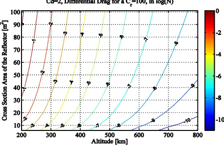
III.III.IIEffects of drag
In the case of LEO, the effects of drag must be taken into account. The atmospheric density ρ was calculated based on the altitude above mean sea level h (in km),
(
)
2 2200
ln 28.59 0.15
46 5
200 0.028 0.013
46 h
h
ρ − ± − −
± −
+ ±
≃
[image:9.595.308.526.104.257.2](9)
Fig. 10 shows the magnitude of the drag on a satellite, assuming a concentration ratio of 100 and co-efficient of drag cd of 2.
Fig. 10. Measure of the differential drag based on the cross-sectional area of the solar reflector, and the satellite altitude above mean sea level.
IV. CASE STUDIES
Two scenarios were studied: de-orbiting a piece of debris from LEO into the atmosphere where it would burn up, and raising the orbit of the debris from GEO to the graveyard orbit,
IV.I. LEO Decay
Fig. 11 and Fig. 12 show the operational time as a function of AMR required to de-orbit a piece of LEO debris from an 800 km altitude circular orbit, to an altitude of 200 km. In this case it was assumed that the debris is mainly covered in solar cells with an absorptivity α = 0.8, reflector efficiency η = 0.9, and a scattering factor λ = 4/(3π). Higher reflective material and more regular, non-tumbling objects can be removed even faster.
IV.II. GEO to Graveyard Transfer
For the case of a piece of debris in GEO, the target disposal orbit can be the graveyard one. The graveyard orbit altitude depends on the AMR and optical Fig. 11. Time to bring a piece of debris from an 800 km
[image:9.595.309.515.312.446.2]orbit down to a 200 km orbit with a constant thrust, and piece of debris assumed to be in constant sunlight.
[image:9.595.57.286.543.694.2]properties of the debris. According to the Inter-Agency Space Debris Coordination Committee, the minimum perigee altitude above the geostationary orbit ∆h should be (in km):
(
)
235 1000 SP /
h C A m
∆ = + (10)
based on the solar radiation pressure coefficient CSP
(typically between 1.2 and 1.5) and the area-to-mass ratio A/m of the debris. The Gauss planetary equations were integrated assuming that the perigee has to rise above the prescribed altitude variation expressed by Eq. (10).
Compared with LEO, raising the semi-major axis to the graveyard orbit is easier. For example, a 1 ton rocket body with AMR = 0.001 m2/kg can be transferred in 1 year by 3 satellites each with a 5 m diameter reflector. Fig. 13 shows the time to transfer a piece of debris from the GEO orbit to the graveyard orbit, for various concentration ratios and AMRs.
V. CONCLUSIONS
The use of solar concentrators, either by directly sublimating the surface material or by exploiting solar pressure, based on these results proves to be a promising method for the removal of space debris around the Earth. There are a number of advantages and disadvantages between the two methods, and a number of open issues that will need to be investigated in future studies. The concept of ground-based lasers for debris removal is not completely new: Early et al.21 and the NASA Orion program are previous examples of the use of ground based lasers to sublimate pieces of debris and generate a thrust. The novelty of this concept is the use of space based lasers. The main advantage of a space based laser compared to the ground based one are: the laser can be operated along the whole orbit, there is no atmospheric interference that degrades the quality of the beam, a lower installed power is needed, offers more precise control over the sublimation point and can be used in any commercial orbit.
The laser ablation system appears to be suitable for all commercial orbits although its applicability depends
on the achievable momentum coupling. In addition, the laser can be operated at larger distances compared to the light pressure (direct imaging from the solar concentrator) but for better efficiency the satellite still needs to track or chase the piece of debris. The light pressure system meanwhile is not dependent on the subsurface material while the laser ablation system might require homogenous surfaces. The light pressure enhancement system is limited by the size of the reflector and by the minimum altitude.
A number of issues still remain to be investigated, such as a thermal analysis and issues related to tumbling. A requirement of this method is that the debris must have an available surface to be ablated; inhomogeneous or multilayer materials also carry the risk of generating splinters.
Lastly, the current TRL of this concept is quite high (>4 on average) as both laser and EPS have been tested in space or in lab environment, and advancements in lasers and solar cells are expected to be fast over the next 5-10 years independently of space-based application.
1
Melosh, H. J., Nemchinov, I. V., and Zetzer, Y. I. 1994. Non-nuclear strategies for deflecting comets and asteroids. In: Gehrels, T. (Editor), Hazard due to comets and asteroids, pg. 1111-1132. University of Arizona Press.
2 Kahle, R., Kuhrt, E., Hahn, G., and Knollenberg, J. 2006. Physical limits of solar collectors in deflecting
Earth-threatening asteroids. Aerospace Science and Technology, 10:253-263.
3 Maddock, C., Sanchez Cuartielles, J. P., Vasile, M., and Radice, G. 2007. Comparison of single and
multi-spacecraft configurations for NEA deflection by solar sublimation. In: Belbruno, E. (Editor), New Trends in Astrodynamics and Applications III. American Institute of Physics, 886:303-316.
4 Vasile M., Maddock C. On the Deflection of Asteroids with Mirrors. Celestial Mechanics and Dynamical
Astronomy, Vol. 107, Issue 1, 2010, pp. 265-284.
5 Vasile, M., Maddock, C., Radice, G., and McInnes, C. 2009. Call for ideas: NEO Encounter 2029, NEO deflection
through a multi-mirror system. Technical Report Ariadna ID: 08/4301, Contract Number: 21665/08/NL/CB, ESA/ESTEC Advanced Concepts Team.
[image:10.595.305.518.105.228.2]6 Musci R., Schildknecht T., Ploner M. Analyzing long observation arcs for objects with high area-to-mass ratios in
geostationary orbits. Acta Astronautica, Vol. 66 (2010), 693-703. 7
Pardini C., Anselmo L., Long-term evolution of geosynchronous orbital debris with high area-to-mass ratios Transactions of the Japanese Society of Aerospace Sciences, Vol. 51, No.171, pp.22-27, 2008.
8 Anselmo L., Pardini C. Dynamical evolution of high area-to-mass ratio debris released into GPS orbits. Advances
in Space Research, Vol. 43 (2009) 1491-1508.
9 Vallado, D.A., Fundamentals of Astrodynamics and Applications 2nd Edition, published by Microcosm Press and
Kluwer Academic Publishers, 2001
10 Anz-Meador, P.D., Potter, A.E., Density And Mass Distributions Of Orbital Debris, Acta Astronautica 38(12),
927-936, 1996
11 Pardini, C., Anselmo, L., USA-193 Decay Predictions Using Public Domain Trajectory Data and Assessment of
the Post-Intercept Orbital Debris Cloud, Acta Astronautica, Vol. 64 (2009), pg. 787–795. 12
Schildknecht, T., Musci, R., Florer, T., Properties of the High Area-to-Mass Ratio Space Debris Population at High Altitudes, Advances in Space Research 41 (2008) 1039–1045
13 Johnson, N., Evidence for Historical Satellite Fragmentations in and near the Geosynchronous Regime,
Proceedings of the Third European Conference on Space Debris, 19 - 21 March 2001, Darmstadt, Germany, ESA Publications Division, ISBN 92-9092-733-X, 2001, p. 355 – 359
14 Saunders, C.J., Modelling of the Optical Observations of a Geosynchronous Fragmentation Event, Acta
Astronautica Vol.60 (2007) 752-762
15 Gravseth, I.J., Culp, R.D., Determination of the Sizes and Masses of Debris Objects, paper AAS 96-114, presented
at the AAS/AIAA Spaceflight Mechanics Meeting, Austin Texas, 12-15 February 1996 16
Vasile M., Maddock C. and Summerer L., Conceptual Design of a Multi-Mirror System for Asteroid Deflection, 27th International Symposium on Space Technology and Science, 5-12 July 2009, Tsukuba, Japan
17 Sanchez Cuartielles, J. P., Colombo, C., Vasile, M., and Radice, G., Multi-criteria comparison among several
mitigation strategies for dangerous near earth objects, Journal of Guidance, Control and Dynamics 32, pp. 121-142, 2009.
18 Phipps, C., “Laser applications overview: The state of the art and the future trend in the United States”, RIKEN
Review No. 50: Focused on Laser Precision Microfabrication (LPM 2002), January 2003.
19 Battin, R. H., An Introduction to the Mathematics and Methods of Astrodynamics. AIAA Education Series,
Revised edition, 1999. 20
Schaub, H. and Junkins, J. L., Analytical mechanics of space systems, First edition, AIAA Education Series. AIAA, Virginia, U.S.A., 2003.
21 Early J. T., Bibeau C., Phipps C. Space debris de-orbiting by vaporization impulse using short pulse laser.