Article
Experimental Analysis of Non Tracking Solar Parabolic
Dish Concentrating System for Steam Generation
Meenakshisundaram Arulkumaran
1,*and William Christraj
21 Department of Mechanical Engineering, Oxford Engineering College, Tiruchirappalli, PIN: 620009, India 2 Department of Mechanical Engineering, Shri Angalaamman College of Engineering and Technology, Tiruchirappalli, PIN: 621105, India
E-mail: arulkumaran_m@yahoo.co.in*
Abstract. This report presents experimental platform based on the design, development and
performance characteristics of direct steam generation by non-tracking solar paraboloidal dish concentrating system. The performance of the concentrator is experimentally investigated with the water circulated as heat transfer fluid. The system is fabricated with highly reflective aluminium foil sheet. The experimental setup is placed in open, and the tests were carried out. The collector’s efficiency was noted. The results are encouraging to provide the data for developing steam generation for rural application. The concentrated heat is absorbed by a copper tube which is made up of coil in a curved shape and it is fixed on solar trace path in which, it is eliminates tracking the sun in the east west direction and optimal tracking of the sun in the north-south to obtain maximum solar energy. The experimental results are taken on summer and cloud free days. The test results were measured 215oC with solar steam
conversion efficiency is 60-70% measured.
Keywords:Concentrator, dish, solar energy, solar trace, sun tracking.
ENGINEERING JOURNAL Volume16Issue 2
Received 9 December 2011 Accepted 26 January 2012 Published 1 April 2012
1.
Introduction
Energy is considered a player in the generation of wealth and also a significant component in the economic development .Renewable energy is accepted as a key source for the future. It is generally accepted that renewable energy technologies contribute to the robustness and stability of an energy system; the system becomes more sustainable. In developing world shortage of fuel for conventional emphasizes the need for alternate energy sources and the most pollution-free, limitless source is solar energy and with the gradual depletion of fossil fuels on the earth, the study of solar energy has become a subject of renewed interest. It is said to be rapidly approaching the point where capital costs of solar energy system will be less than those of nuclear systems. It is unlike other sources of energy, solar energy allows independent systems to be constructed possessing a thermal conversion mode that necessitates a simple technology, which is adapted to this site and to the particular region for many applications. The implementation of solar power plants in regions of high isolation is a promising option for an environmentally compatible electricity supply strategy. The existing solar paraboloidal dish concentrators are used for power generation purpose heating and steam generation applications. The heliothermal system in which the incident radiation absorbed is turned into heat [1]. There are three modes of solar energy utilized as helio thermal, helio chemical and helio electrical. The heliothermal system is used for the conversion of solar radiation into heat. The availability of solar energy on the earth surface depends of geographical location. India is a favourable location for solar energy development.
1.1. The Sun's Energy
Sun is the singular source of renewable energy that sits at the center of the solar system. It emits the solar energy as electromagnetic radiation at an extremely large and relatively constant rate through out the year. This energy is released at the rate of 3.83 × 1026 W. The rate at which this energy is emitted is equivalent to
the energy coming from a furnace at a temperature of about 6000 K. If the energy coming from just 10 hectares (25 acres) of the surface of the sun could be harvested, it would be enough to supply the current energy demand of the World. However, there are three important reasons why this cannot be done: The earth is displaced from the sun. Only a small fraction of the energy leaving an area of the Sun reaches an equal area on the Earth. The earth rotates about its polar axis, so that any collection device located on the earth’s surface can receive the sun’s radiant energy on about one-half of each day. The condition of thin shell of atmosphere that surrounds the earth’s surface is the third reason. At best, the earth’s atmosphere accounts for another 30 percent reduction in the sun’s energy. As it is widely known, however, the weather conditions can stop all but a minimal amount of solar radiation from reaching the earth’s surface for many days in a row. The rate at which solar energy reaches a unit area at the earth is called the solar irradiance or insolation. Solar irradiance is an instantaneous measure of rate and can vary over time. The maximum solar irradiance value is used in solar system design to determine the peak rate of energy input into the system. The designer of solar energy collection systems is also interested in knowing how much solar energy has fallen on a collector over a period of time such as a day, week or year. This summation is called solar radiation or irradiation.
2.
Theoretical Background
The point focusing parabolic dish concentrator can have concentration ratios ranging from 100oC to a few
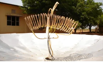
ENGINEERING JOURNAL Volume 16 Issue 2, ISSN 0125-8281 (http://www.engj.org) 55 and making it as a curve towards the movement of the sun and making as a trace it can be called as solar trace and focusing through this path is most advantages over other systems. In two axis tracking east-west and north-south are required and commonly used in practice, and this paper eliminates there is no tracking in east-west, optimized with intermittent tracking is needed in the south west directions and it is always placed normal to the incoming solar radiation rays to obtain higher efficiency and to get more energy to be captured throughout the year. It has been a fabricated dish concentrator from small elementary shapes from highly polished aluminum sheet. These elemental components are commonly called as reflecting materials. This investigations and research work to design, development fabricate a parabolic dish steam generation equipment which is used as for solar energy and to carry out performances analysis of a parabolic collector to achieve the change phase as steam at the focal solar trace in the simultaneous movement of sun of the concentrator Parabolic dish system principle is developed and an experiment has been constructed as shown in Fig. 2. It is comparatively small unit which used to be a dish shaped reflector, concentrated sunray heats the water and super heated fluid used to generate the steam for larger capacity plants, a number of dishes may be used.
Fig. 1. Solar collector principle.
3.
Experimental Platform and Procedure
The parabolic dish concentrator for the steam generation and the experimental setup has been developed for the performance analysis. The experimental setup consists of a solar parabolic dish system, absorber, heat transfer fluid as water and it is circulated through the system. The cooling water tank is fitted with the experimental setup. A galvanized steel pipe is used to carry the water from tank to the absorber tube and absorber tube is a coiled tube made up of copper. It is located in the focal point on the solar trace and parabolic dish when the sunlight rays are incident on the reflective surface of the parabolic dish. They are reflected and conveyed to the surface of the tube at the curve to heat the water and to take change phase. The parabolic dish made with highly reflective with 0.8 of reflectance factor, surface focusing and it is employed as moving towards the movement of the sun. There is no coating over the surface of the tube and further investigation to be carried out for black coating and covering the absorber to reduce the various losses. The reflector cut into small shapes and fixed parabolic in which is in turned conveniently. The adjustable mechanism made up of metal to support the weight in which it is tilted to north-south and east-west directions to obtain the maximum amount of energy depending upon position of the setup and the position of the sun.
[image:3.595.195.393.602.722.2]The out let pipe is connected to the other end of the absorber tube and generated steam is delivered to the application. The circulating fluid flow measured by collecting in a vessel with respect to the time. The reflection surface can be deteriorated when exposed to the open atmosphere, and it can be cleaned by rubbing polish and can be washed. It can be maintained with good environment stability and weatherablity to be monitored during the test. Many methods have been developed to study the focal image characteristic of heat flux and heat flux on the absorber [3].
4.
Non-Tracking Principles and System Development
In these parabolic concentrating rays towards the solar trace, it eliminates tracking of the sun concentrator which are (i) east-west and (ii) north-south directions. This paper presents that no tracking is needed according to the solar altitude angle and azimuth angle. The solar altitude angle is made from a point on the surface of the earth and to the centre of the solar disk and is lined extending horizontally from the point. It is merely on the particular year, whereas the azimuth angle is effectively used in solar energy radiation heating application and it absorbs or collects as much of the solar energy as possible. The azimuth angle plays major part in obtaining the greatest possible solar energy production. It is the horizontal plane measured from the south, for location in the southern hemisphere. Every day the sun rises from the east to west from the zero altitude angles, reaches to maximum at noon, and gradually decreases to west, where as the azimuth angle decreases up to solar noon and equal zero at solar noon. Afterwards the azimuth angle increases. The two angles vary depending upon the position and location of particular time of a day in year. The altitude angle at noon time for particular day is obtained as 56o [4]. Figure 3 shows the solar trace
which obtained by line joining of intersections of reflected sun’s rays in the parabolic dish concentrator for the straight path of the sun. The solar radiation is explained in a clearway in Fig. 3 and the intensity of solar trace is maximum at the trace of the path. The absorber is kept along the trace shown Fig. 3, and the maximum intensity of radiation is obtained.
Fig. 3. Solar trace.
The experimental setup has been set at Tiruchirappalli India is between Tropic of Cancer and Equator on earth so altitude angle is measured from the south during the period the declination angle is greater than the latitude angle of the place. All other locations above the Tropic of Capricorn are in the southern hemisphere the latitude angle is measured only from the north. It will help us to change the direction of PDC in the north south direction. The maximum difference in the solar altitude angle at a given position of the PDC for the entire period of 15 days is only 6.036o. The PDC requires to be changed once in 15 days
[image:4.595.138.456.404.660.2]ENGINEERING JOURNAL Volume 16 Issue 2, ISSN 0125-8281 (http://www.engj.org) 57 of altitude angle varies from 0o to 6.036o and the maximum difference in the solar altitude angle for the
chosen position is 6.036o.
Fig. 4. Diameter of the absorber.
5.
Design of Absorber Size
Figure 4 shows the sun’s rays incident on the surface of the dish in the north-west direction for particular time of a day for the particular position and the points FNand FS are obtained carefully if the absorber is
placed between FSand FN the maximum solar radiation is obtained.
The absorber diameters AE is found as
D[cot(θ-λ/2)-cot(θ+λ/2)]/[cot(θ-λ/2)+cot(θ+λ/2)] (1) where θ is the angle of aperture in degrees; and λ is the solar altitude angle in degrees.
The following measurement of parabolic dish concentrated was designed: the diameter of the parabolic dish concentrator 2.70 m; the focus is 1.30 m; the location is 10.46o N and 78.43o E fixed at
Tiruchirappalli-India; the coil diameter is 0.30 m; and the copper tube diameter is 15 mm.
6.
Thermal Analysis
The concentrated solar sun rays is absorbed by the absorber tube which is made up of copper coil absorbs high concentrated heat due to the reflection of the sun’s rays and the transformed energy to be used in subsequent process. The specific significant is to absorb the maximum amount reflected energy and transfer it as heat with minimum heat loss to the heat transfer fluid due to arrangement made as in the focusing curve and generally a cavity receiver is used to accomplish [2] where as present dish concentrator involves the focal image width measured as equivalent to the diameter of the absorber. The solar thermal energy by the water Qeff is computed by
Qeff = ρVCp (To-Ti) (2)
where Cp is specific heat (J/kg K); ρ is the density of fluid (kg/m3); V is the volume flow rate of the fluid
(m3/s); Ti and To are inlet and outlet temperatures of the fluid. The main significance of the equation is to
determine the heat transfer rate of circulating fluid and to make the thermal analysis. The solar collector efficiency can be calculated by
ηc= Qeff / IA (3)
where I is the solar flux (w/m2)and A is the effective area (m2) of absorber. The heat losses included from
the receiver as Qr radiation, Qc convection and Qcd conduction losses are computed as follows:
Qc =h π D (Tg-Ta) (4)
Qr = σπD ε ((T4g-T4sky) (5)
[image:5.595.109.483.119.328.2]where the Tskyand Tg are temperatures of the sky and outside the wall of the receiver; ε is emissivity; h is
heat transfer coefficient; Kr thermal conductivity; D is the diameter of the coil. The detail report on the
numerical simulation method for collector performance can be found in the work [5].
7.
Testing
Testing was done during the summer and clear sky with cloud free days during the month of April 2011 in experimental for about six to seven days. The experimental setup placed in open place with clear sky. The tests were taken between 10 am to 4 pm in data were taken on each hour for 7 hours. The k type thermocouple with digital indicator used to measure temperature at the focal solar trace to obtain various temperatures and maximum temperatures. The solar insolation during test period is 450-470 w/m2
measured. The number of turns in the coil is 24 and residence time is adjusted manually during the test period.
Table 1. Results on 3rd April 2011.
Time Ta ambient
temperature oC T
g receiver
temperature oC
10 am 31 100
11 am 32 125
12 no 34 128
1pm 35 160
2pm 34 215
3pm 33 198
4pm 32 145
Table 2. Results on 6th April 2011.
Time Ta ambient
temperature oC
Tg receiver
temperature oC
10 am 30 101
11 am 31 120
12 no 32 135
1pm 33 165
2pm 34 207
3pm 33 19
4pm 31 150
Table 3. Results on 10th April 2011.
Time Ta ambient
temperature oC
Tg receiver
temperature oC
10 am 30 105
11 am 31 128
12 no 32 140
1pm 33 170
2pm 34 210
3pm 33 180
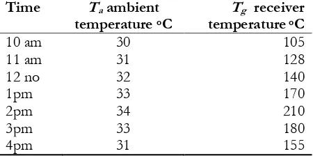
[image:6.595.187.410.296.410.2] [image:6.595.181.416.460.573.2] [image:6.595.186.411.624.736.2]ENGINEERING JOURNAL Volume 16 Issue 2, ISSN 0125-8281 (http://www.engj.org) 59 Table 4. Results on 12th April 2011.
Time Ta ambient
temperature oC
Tg receiver
temperature oC
10 am 30 105
11 am 31 128
12 no 32 140
1pm 33 170
2pm 34 215
3pm 33 180
4pm 31 155
8.
Results and discussions
The performance characteristics of the parabolic dish concentrator depends on such as solar flux, the flow rate water and heat loss influence the performance of PDC for the steam generation, therefore accounts in this study, experimental investigations were carried out and results were recorded. Based on the results obtained during the test of PDC steam generator the temperature above 210oC was recorded with the
ambient temperature, the maximum value reaches at about 2.00 pm and temperature varies along the solar trace on the absorber tube and over the surface area. The different flow rate has been carried out for the generation steam but the flow rate results were not presented. When 0.35 kg/s flow rate condition boiling takes place about 15-30 minutes during maximum temperature higher than 190oC and average soar beam
radiation measured as 490 w/m2. In practice cylindrical parabolic solar reflectors require one axis of
tracking together with periodic manual adjustment of the reflector axis elevation angle to allow for changes in the declination angle. Two axis-tracking systems are required for paraboloidal concentrators and for solar measurement applications. Both one and two axis tracking system are required for paraboloidal concentrators and for solar measurement application. It is concluded that it is an alternative solution to solve the need of thermal energy in various applications and exclusively for rural applications for drying food grains and roasting, boiling. It is very effective heat transfer equipment and this type concentrating collectors are used for application where efficient operation is required for fluid temperatures in excess of 100C. It is time to know about the need for alternative energy sources and educate the community of alternative sources of energy. Hence the development of renewable energy is moving fast. The performance of photovoltaic arrays follow the solar vector but the capital cost of the tracker system and the increased maintenance needed would offset the improvement. Measuring beam radiation is also required to track the sun and any of these applications the sun’s position must be tracked accurately to obtain maximum benefit from the collector system or instrument. Nationally and internationally various individuals and research companies are creating new and exciting energy systems towards the investigations on PDC. This type of solar energy generation will help the problem of the future identification in the society, these energy sources are abundant and free to use and should be sure that converts the energy in the right way.
References
[1] J. Folaranmi, “Design and construction of a parabolic solar steam generator,” Leonardo Electronic Journal of Practices and Technology, vol. 7, no. 14, pp. 115-133, 2009.
[2] N. D. Kaushika and K. S. Reddy, “Performance of a low cost solar paraboloidal dish steam generation system,” Energy Conversion and Management, vol. 41, no. 7, pp. 713-726, 2000.
[3] M. S. Patil, M. S. Tandale, and A. G. Chandak, “Heat loss characterization from solar concentrator receiver-a review,” International Journal of Engineering Science and Technology, vol. 2, no. 12, pp. 7531-7539, 2000.
[image:7.595.188.406.105.218.2]