UNIVERSITI TEKNIKAL MALAYSIA MELAKA
SIMULATION OF SPROCKET BY USING DIFFERENT TOOL
PATHS PROCESS IN CAD/CAM SOFTWARE
This report submitted in accordance with requirement of the Universiti Teknikal Malaysia Melaka (UTeM) for the Bachelor Degree of Engineering Technology
(Maintenance Technolgy)
By
NUR RIDHA RIFAIE BIN NOR ZAMRI B071410664
921114146427
UNIVERSITI TEKNIKAL MALAYSIA MELAKA
BORANG PENGESAHAN STATUS LAPORAN PROJEK SARJANA MUDA
TAJUK: SIMULATION OF SPROCKET BY USING DIFFERENT TOOL PATHS PROCESS IN CAD/CAM SOFTWARE
SESI PENGAJIAN: 2017/18 Semester 1
Saya NUR RIDHA RIFAIE BIN NOR ZAMRI mengaku membenarkan Laporan PSM ini disimpan di Perpustakaan Universiti Teknikal Malaysia Melaka (UTeM) dengan syarat-syarat kegunaan seperti berikut:
1. Laporan PSM adalah hak milik Universiti Teknikal Malaysia Melaka dan penulis. 2. Perpustakaan Universiti Teknikal Malaysia Melaka dibenarkan membuat salinan
untuk tujuan pengajian sahaja dengan izin penulis.
3. Perpustakaan dibenarkan membuat salinan laporan PSM ini sebagai bahan pertukaran antara institusi pengajian tinggi.
4. **Sila tandakan ( )
SULIT
TERHAD
TIDAK TERHAD
(Mengandungi maklumat yang berdarjah keselamatan atau kepentingan Malaysia sebagaimana yang termaktub dalam AKTA RAHSIA RASMI 1972)
(Mengandungi maklumat TERHAD yang telah ditentukan oleh organisasi/badan di mana penyelidikan dijalankan)
Alamat Tetap:
NO. 121 Taman Chegar Medang,
Jalan Benus, 28700 Bentong, Pahang Darul Makmur.
Tarikh: ________________________
Disahkan oleh:
Cop Rasmi:
Tarikh: _______________________
iii
DECLARATION
I hereby, declared this report entitled “Simulation of Sprocket by Using Different Tool Paths Process in CAD/CAM Software” is the result of my own research except
as cited in references.
Signature :
Author’s Name : NUR RIDHA RIFAIE BIN NOR ZAMRI
iv
APPROVAL
This report is submitted to the Faculty of Engineering Technology of UTeM as a partial fulfilment of the requirement for the Degree of Engineering Technology (Maintenance Technology) with Honour. The member of supervisory is as follow:
……….. (Project Supervisor)
v
ABSTRAK
vi
ABSTRACT
vii
DEDICATION
Dedicated to my father NOR ZAMRI BIN RASHID and my mother ZAMZILAWATI BINTI MOD ROS. To my supervisor MR AHMAD ZUL HUSNI
viii
ACKNOWLEDGEMENT
First of all, I am very grateful to Allah S.W.T for the good health that was necessary to complete this final year project report. I am also grateful for having been given the opportunity and also a good time to prepare this report. Even though there are many difficulties that I have faced while completing this report, I was able to fulfil my responsibility as a student to complete this task.
I also want to express my appreciation to my parents that always support all the time and to my supervisor because of sharing the experiences, expertise, guidance and knowledge’s while I was doing this task. Thank you also goes for consistent guidance during generating of ideas to complete this report. All the suggestions that have been given can be translated easily into the content of this report to achieve the objective of this study.
I take this opportunity to express gratitude to all of the department faculty members for their guide and support. I also thank my parents for the encouragement, support and attention. Their supports are so important to me during finishing this report.
ix
TABLE OF CONTENT
Declaration iii
Approval iv
Abstrak v
Abstract vi
Dedication vii
Acknowledgement viii
Table of Content ix
List of Tables xiii
List of Figures xiv
List of Abbreviations xvii
CHAPTER 1: INTRODUCTION 1.1 Background 1
1.2 Problem Statement 3
1.3 Objectives 3
1.4 Scope of Project 4
x
2.1.1 Mild Steel Sprocket Material 7
2.1.2 Carbon Fibre Sprocket Material 7
2.1.3 Sprocket Dimension 8
2.2 Cutter Shape and Cutting Condition 9
2.3 Solid Modelling 10
2.4 CAD/CAM 11
2.4.1 CATIA V5 12
2.4.2 CATIA V5 Advanced Machining and Simulation 13
2.4.3 MasterCam 14
2.4.4 MasterCam Advanced Machining and Simulation 15
2.5 Computer Numerical Control 16
2.5.1 5-Axis Milling Operation 18
2.5.2 3-Axis Milling Operation 19
2.6 Tool Movements 20
2.6.1 Tool Path (Zig-Zag) 20
2.6.2 Tool Path (One Way) 21
2.6.3 Tool Path (Helical) 22
CHAPTER 3: METHODHOLOGY
3.1 Overview 24
3.2 Flowchart of the Project 24
xi
3.4 Gathering Information 26
3.5 Apparatus 26
3.5.1 Vernier Caliper 26
3.5.2 End Mill 27
3.5.3 Drill Bit 28
3.5.4 3-Axis Computer Numerical Control Machine 28
3.6 Work piece 29
3.7 CAD/CAM Software 30
3.8 Generating Tool Paths 30
3.9 Sprocket Design 31
3.10 Generating Tool Path for the Simulation Process 35
3.11 Cutting Process 40
3.12 Actual Process by using CNC Machine 44
CHAPTER 4: RESULT AND DISCUSSION
4.1 Result 48
4.1.1 Result of Simulation Process in CATIA V5 49 4.1.2 Result between Simulation and Actual Process 50 4.2 Graph Comparison between Simulation and Actual Process 50
4.3 Simulation Result in CATIA V5 53
4.4 Result of Sprocket Prototype 56
xii 4.5.1 Result Dimension by using Zigzag Tool Path 59 4.5.2 Result Dimension by using One Way Tool Path 61 4.5.3 Result Dimension by using Inward Helical Tool Path 63
4.6 Discussion 65
CHAPTER 5: CONCLUSION
5.1 Conclusion 68
REFERENCES 70
APPENDICES 75
xiii
LIST OF TABLES
2.1 Sprocket styles 6
3.1 Parameter for simulation and actual process 44
4.1 Tool path simulation time taken 49
4.2 Comparison time taken between simulation and actual process 50
4.3 Result dimension by using Zigzag tool path 60
4.4 Result dimension by using One way tool path 62
xiv
LIST OF FIGURES
2.1 Process design of Bajaj pulsar rear wheel sprocket 9
2.2 End mill cutting tool 10
2.3 G codes uses in CNC programming 17
2.4 M codes uses in CNC programming 18
2.5 Zig-Zag tool path 21
2.6 Climb and conventional position 22
2.7 One way tool path 22
2.8 Inward helical operation 23
2.9 Outward helical operation 23
3.1 Flowchart of the project 25
3.2 Example of mild steel 26
3.3 Vernier caliper apparatus 27
3.4 Example of High speed steel cutting tool 27
3.5 Example of Drill Bit 28
3.6 CNC machine (DMC 635 V ecoline) 29
3.7 Example of motorcycle sprocket 29
3.8 Process to design motorcycle sprocket using CATIA V5 34
3.9 Selecting Machining Process 35
xv
3.11 Axial Machining Operation 37
3.12 Cutting Parameter 37
3.13 Tool Path Operation 39
3.14 Cutting Process 40
3.15 Sprocket Simulation 43
3.16 Coding Transfer 45
3.17 Simulation in CNC Controller 45
3.18 Roughing Process 46
3.19 Sprocket Prototype Formation 46
3.20 Sprocket Shape has been Formed 47
3.21 Sprocket Prototype Finished 47
4.1 Graph Simulation Process Time Taken 50
4.2 Graph Actual Process Time Taken 51
4.3 Graph between Simulation and Actual Process Time Taken 51
4.4 Zigzag Tool Path Simulation Result 53
4.5 Roughing Process Time Taken 53
4.6 Drilling Process Time Taken 53
4.7 One Way Tool Path Simulation Result 54
4.8 Roughing Process Time Taken 54
4.9 Drilling Process Time Taken 54
4.10 Inward Helical Tool Path Simulation Result 55
xvi
4.12 Drilling Process Time Taken 55
4.13 Sprocket Prototype 58
4.14 Result Dimension by using Zigzag Tool path 60
4.15 Result Dimension by using One Way Tool Path 62
xvii
LIST OF ABBREVIATIONS, SYMBOLS AND
NOMENCLATURE
CAD Computer Aided Design
CAM Computer Aided Manufacturing
CATIA Computer Aided Three-dimensional Interactive Application
CNC Computer Numerical Control
H/W IT Hardware
ID Identification
ISO International Standard Organization
IT Information Technology
mm Millimetre
mm_mn Millimetre per minute
NC Numerical Control
PMCs Plant Material Centres
1
CHAPTER 1
INTRODUCTION
1.1 Background
In the producing and processing finished products, there are many methods that can be used. There are 4 general different processes which is Casting, Moulding, Forming, and Machining. Focusing to the machining process, that is including Milling, Turning, Drilling, Reaming, Tapping and Sawing. All of these processes are need to be highly considered to find the best process and produce a high and good quality product.
Milling operation is a machining process that is used to remove the material from the work piece in a direction of an angle with the axis of the tool. It used a cutter that rotates to remove the material from the work piece. From the milling machine, it can performed many of operations and function which is starting from the small until to large objects. This process is commonly used in industry and machine shops today for machining parts to design a shape of products no matter it is in complicated design (Smith, 2016).
2 Other than that, milling also is a cutting process that to removed or cutting away the wasted material. The machine must be running in a high speed to rotates the sharpen teeth of cutting tools for removing the unwanted material. When the work piece is place below the cutting tool, the material will be cutting from the work piece and create a desired shape or design. To produce parts or products which are not axially symmetric and has many features on it like holes, slots and even three dimensional contours the milling machine can do the operations. The milling cutters will be cutting the work piece surfaces on each side for the periphery milling. There are two types of milling machines which are vertical and horizontal milling machine (Steve, n.d).
Vertical mill has a spindle axis that is arranged to make a rotation by stay at the same axis and get two further categories which are bed and turret mill. For bed mill, it has spindle that moved parallel to the axis and a perpendicular moved for the table to the axis. Then, for turret mill the spindle is working to remove the unwanted material which is the table is moving perpendicularly and parallel to its. Horizontal milling also has a same cutting tool but the cutting tools are placed on the horizontal axis. The rotary tables will help in milling operation in a various angle that is getting on a lot of horizontal mills. It’s also called universal tables and from the vertical cutting tool mill can be also used in horizontal mill (Steve, n.d).
3 1.2 Problem statement
Machining process of producing motorcycle sprocket will take a long time to complete if improper selection of tool paths is made (Australian Manufacturing Technology, 2011). The suitable selection of tool paths in the advanced machining process for producing motorcycle sprocket is very important. Furthermore, with the improper selection of tool paths during the advanced machining process, this situation affects the rate of production time (Australian Manufacturing Technology, 2011).
Besides that, the tasks of time minimization of various types of cutting techniques are formalized which are three types of different tool paths will be selected (Petunin, 2016). The possible ways to fabricate the motorcycle sprocket are identified and will simulate the fastest way between three various types of the tool paths to reduce machining time and produced quality product.
1.3 Objective
The several purposes of the studies about to design and simulate the motorcycle sprocket with three different tool paths machining processes by using CATIA V5 software and fabricate the prototype using Computer Numerical Control (CNC) machine to compare the time taken between simulation and actual process below:
a) Design the part of sprocket and perform simulation for several different tool paths of machining process on the sprocket using CATIA V5.
4 c) Determine the fastest time of tool paths for the actual machining
process.
1.4 Scopes of the project
Motorcycle sprocket is a part which is order from the customer by following their own specification. Motorcycle sprocket has main function is to transmit power and motion to the motorcycle for make a movement. In this case, motorcycle sprocket will be normally used for the motorcycle performance which is in race competition. Firstly, the prototype of motorcycle sprocket will be design by using the CAD: Computer Aided Design which is CATIA V5. Then, after the design is completed, the simulation of advanced machining processes for the prototype will be performed and the coding will be generated by using the CATIA V5.
In this case, there are three different tool paths operation will be selected which is to perform the simulation of the motorcycle sprocket prototype. There are three tool paths operation that will be performed which are Zig-zag, One Way and Helical operation. Besides that, the two CAD software were selected in order to compare which software is more accurate for command reading in the system and less time is taken to produce the motorcycle sprocket prototype.
5
CHAPTER 2
LITERATURE REVIEW
2.1 Sprocket
Sprocket is a wheel which is have a sharpened toothed around it that is designed to connected with something that will be pulled over the wheel when the wheel is being rotates. These sprockets are similarly looked like a gear, but not like gears which are they are not designed to be destructed with other gears. These basic designs for the simple mechanical component have been used around the world for long time ago and will be used in many of applications starting from in advancing the film for disposable camera to the powering professional class bicycles. One of the famous settings for a sprocket is used in a bicycle, where the sprocket is connected to the chain to transform a movement for the bicycles when the riders make a stroke into the rotation of the wheels. The size of the sprocket also can be adjusted to make change of gearing of the bicycles for the different cycling situation or operation. Other than that, the sprocket also is used in motorcycles manufactured and some other types of motorized vehicles. Based on (Williams et al., 2014) these motorcycles sprocket is also important mechanical component to transmit power and motion to the motorcycles for make a movement. Furthermore, for motorcycles sprocket it has two types of sprockets which is coming in pair for rear and front sprocket. The chain will get a connection to the rear and front sprocket which is front sprocket will drives the rear sprocket to make an operation (Ambole, n.d).
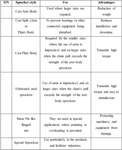
6 the table 2.1 below will showed the classification of sprocket by general form (Williams et al., 2014).
S/N Sprocket style Use Advantages
Cast Arm Body Used where larger sizes are required.
Reduction of weight Cast Split (Arm
or Plate) Body
To prevent bearings or other connected equipment being
disturbed.
Reduces installation and
downtime.
Cast Plate Body
Required for the smaller sizes where the use of arms is impractical and on larger sizes when the chain pull exceeds the
strength of the arm body sprockets.
Transmits high torque
Fabricated steel sprockets
Use of arms is impractical and on larger sizes when the chain’s pull exceeds the strength of the arm
body sprockets.
Transmits high torque and easy to
manufacture
Shear Pin like flanged
rim
They are used in special applications where jamming or
overloading is prevalent
Protecting machinery and equipment from
damage.
[image:23.596.106.531.153.677.2]Special Sprockets Use particularly in the products and fertilizer industries.
7 2.1.1 Mild Steel Sprocket Material
The motorcycle sprocket is made in many types of material which is for example is mild steel material. The analysis for the mild steel material has been done which known as steel is a traditional material for a sprocket chain. Furthermore, steel also is easy to get and the machinery for machining process of steel also is easy to get. The market price for steel is cheap compare to the other materials. With this advantages that have at mild steel, this is why about 99% of the sprocket chain is made from mild steel. Steel also have its own characteristics which is stiff but dense (heavy). Other than that, steel have a good ratings in terms of both yield strength and ultimate strength, especially if the material is carefully alloyed and processed. Besides that, steel also against the fatigue failure which is very useful for the sprocket manufacture even the sprocket chain is under load for example the steel need to flexing but it will not lead to a critical failure (Ambole, 2016).
2.1.2 Carbon Fibre Sprocket Material
Carbon fibres have provided the most basics for the development of Plant Materials Center (PMCs) as an advanced structural for engineering materials. In general term of materials, low modulus fibres have lower specific gravities, lower cost, higher tensile strength to failure than high modulus fibres, higher tensile and compressive strength. The carbon fibres have many of advantages which their extremely high tensile strength to weight ratio and tensile modulus to weight ratios. Furthermore, carbon fibres also have high fatigue strengths (Ambole, 2016).