I PULSE-CODE MODULATION
II EQUIPMENT INCIDENTAL TO MAIN PROJECT
by G.V. DUNNE, B.E. (Hone), B.So
Submitted in fulfilment of the requirement for The Degree of Master of Engineering Science
December, 1963.
TiCSIS
"01432.00DB MODULATION" by G.V. ]nne
imams
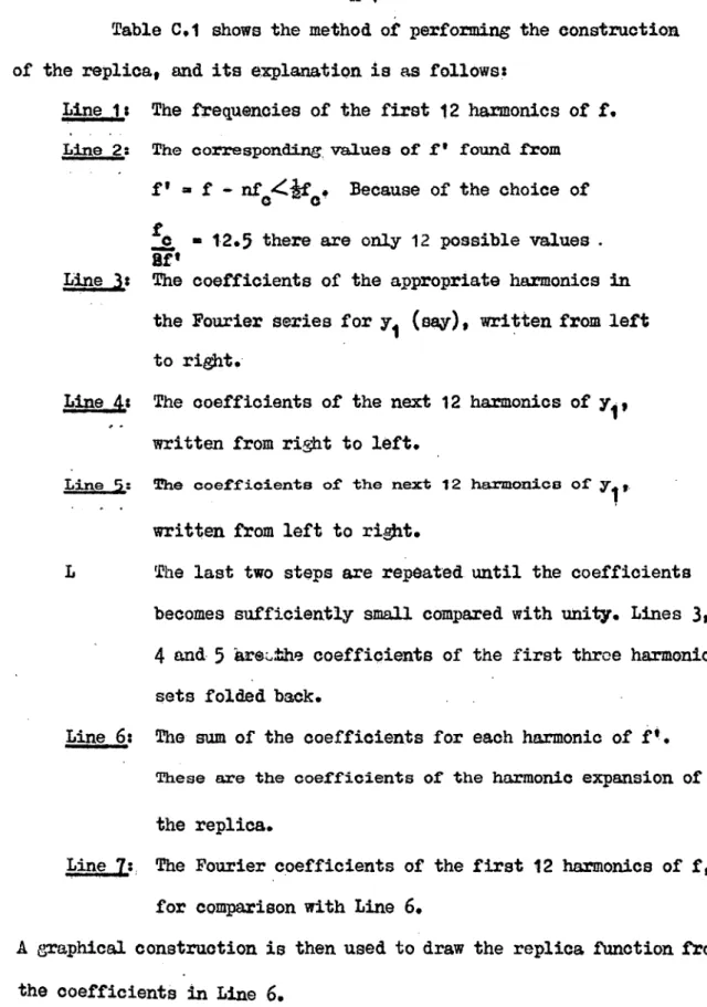
I. The word °quantized" has been consistently misspelt "qoantitized".
2. Paso 01# last paraaph • lino
4
should reads
"... pulse() of unit amplitude, width
t;and ..."
1/9. ParnEIVVI lines 8 #
9
should road;
fs
(51.0)=
F 0%) . (j63 7•)
ou•00 03
- olX,
RILle 00* para3raph 3 0 linee
7,
8 should roads
"... reprozonts the ratio of tho samplincp.pulse width to period"
5. Paos
pararaph .2 1 line 0 should reads
"peak sicnal to rms noise isjile # and the ..."
Pulp
Parazraph 20 line 0 Should reads
"... Shannon° was sent or
or its
Catlit3inea
pulse to bo deleted".
RIO)
2164
Para3raph 20 line
4
should read:
"...The type of iagormation which must aocompany..."
8. PaLm 0 0 park:raPh
5,
line
5
Should read:
"...which scanned
themask in..."
9. Paje
para,7aph 1 # lino 1 Should reads
"...be comparod with tUe input and used to stop..
10.Pacp
partk3raph 2 1 line 11 Aleald reads
"...every neutive diMrence to no dij.t..."
11.Pkp
2/61p,-Ira7aph 3, line 2 should reads
"an the accuracy o: the wei:Pted voltacso..4"
12.Pace 2/10. para_raph
2,lino 1 should road:
"...obeys equation
i"
U.
P4km 03, Park7a9h 4. lit*
5
should reads
"...can react to chanze and on the juin..."
14* Pace 3/101
Para.,r010h 2, insert between lines 5 and 611
/16
popeal0 feur-inpat AU gates to
,
IALrA-Auph 5 0 line
7
omit "by all the stores"
Re 3/13 1
paraaphli'llte
9
should read;
"...voltazee to decrease in"
17.
rAaze3/18, raraph 21 lino 3 ohould
read:
0
.. .clamp capacitor",
10. Pao A/2 # equation lendkn3 to equation 10) should reads
1(
k
) 5
1
17t
CE6). t.
e
dcii190 Pa WI, parecraph 5 # line 1 should reads
CONTENTS
SULLIARY
I PULSE CODE MODULATION
SECTION 1 Pulse Code Modulation
2 Production and Demodulation. of PCL1 3 MI Equipment
4
Sampling Phenomena5
References and BiblioapbyAPPENDIX A Sampling Theorem Prot):
B Bistable Multivibrator Design
C Replica Construction
D Applications of Synch Detector
II EQUIP" L7CILMITAL TO MAIN PROJECT
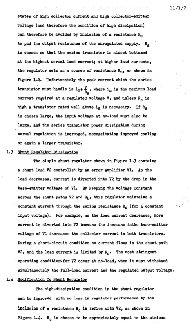
SECTION 1 Regulated Transistor Power Supplies
2 Portable Bridgef4t Borehole temperature Measurement 3 Ruler Time-scale Unit
or
I
This thesis describes work doneson the Zlectrical Engineering Department of the University of Tasmania from April 1959 until March 196Q under the supervision of Professor G.H. Newstead.
At that time the Department was concerned with providing equipment for telemetry of very low frequency seicmic data from remote stations in Tasmania* In support of a proposal that PC N transmission be used due tots claimed high noise-immunity, a theoretical investigation of the characteristics of Pal was carried out, and simple transistorized equipment was developed for this application: a coder and decoder for
the data, and regeneration and synchronization equipment for the transmicsion link.
Other equipment concerned with the instrumentation of geological
work was designed and built for the Department during this period. It
included a portable unit for measuring borehole temperatures, standard
time-signal equipment for the laboratory and high-current regulated paver
supplies for transistorised equipment.
When this work was undertaken the use of transistors was very
restricted and little experience had been gained in the Department in
their application. Consequently, this thesis reports some of the early
PULSE CODE MODULATION 1/1 • INTRODUCTION:
Pulse-code modulation is an appealing topic. It has interesting theoretical aspects, leading into the fields of
information and communication theory, and its practical relization involves a rare combination of analogue and digital techniques in which the circuit designer can exercise his ingenuity. Work on both these facets of PCM is reported here.
In the first Section the history of the development of
pulse-code modulation (PCM) is surveyed and its important characteristics are considered theoretically.
The second Section contains descriptions of practiEal methods for achieving the coding operation, for synchronizing the demodulator with the modulator, and for regenerating distorted pulses.
The equipment which was designed and built for the project
is deocribed in Section
3,
together with its performance as a synchronizedcoder and decoder.
In Section
4
an interesting result of the Sampling Theorem is investigated and given experimental illustration by use of the PCM equipment.Appendices A, B o C and D contain, respectively, a proof of the Sampling Theorem, an analysis of some of the circuits, a graphical construction for waveforms relating to Section 4, and other applications for the synch detector described in Section 2.
1.1 Historical Surrey of Pal Deve1opmeq4
Pulse-code modulation (PCM) was invented in
1937
by Reeves(1) in the French laboratories of a telephone and telegraph company. has been seeking to obtain for speech transmission the digitaladvantages of telegraphy, namely pulses of fixed height which may be regenerated as often as desired along communication links. Another advantage which he realised was the inherent suitability of the method
for time-division multiplexing of many signals on one channel.
The first practical work on PCM was done in the Boll Telephone
outlined the equipment used in their system. The advantages of PCM were also put forward by Black and Edson (415) in an early theoretical treatment. Panter
et al from the ITT Company were concerned with the effects of coding, and published two papers(67) on
quantitization noise and distortion of speech. A major contribution to PCM development came
from Meacham and Peterson of Bell Laboratories who announced (8) the first experimental multichannel link
technically good enough for use in existing telephone systems, but although they quoted performance data for the link the equipment was not detailed. However, Sears (9) gave a description of an electron-beam coding
tube in the same journal, and later Carbrey(1o) showed a simple circuit, called the Shannonallaok decoder, for
decoding binary pulsed and it is highly probable that
these were the devices used by Meacham.
In 1948 a large amount of material on communication 9
and information theory was being published(h112131415)
and PCM was receiving a theoretical analysis (16h718 ) when the classic summary of its properties was given by Oliver, Pierce and Shannon(19) in terms of the work of
Nyquist and Hartley. They explained the processes of
sampling quantitization and coding, and showed how coding
improved the noise threshold and used the needed extra bandwidth to better purpose in signal-to-noise ratio return
than FM. Several other author8 (20 ' 21 222324), all concerned
with speech transmission, turned to methods of reducing
coding noise by the use of unequal quantitizing levels. Thus, by the end of 1948 most of the factors required for
long-distance speech communication by PCM were well realized.
But, after two papers(2526) dealing with the signal-to-noise
ratio
improvement of PCM over other modulation methods, the literature on theoretical aspects became suddenly vacant for1/3
about four years until Villars(27) gave further work on coding and Page(28) and Hichols(29) mentioned PCM in comparing different methods of multiplexing and modulation.
Implementation aspects of PCM also showed a pause of about four years after Ostendorf's 1949 description(30) of the principles of a pulse-regenerator for repeater stations. However, an important paper on binary coding, net then related to PCN4 was published in 1949 by Barney(31) who described in detail an original analogue-to-digital converter using a tracking up/dovn counter and analogue feedback. The gap was ended when Oxford(32'33) published the first work done on PCM speech transmission outside a telephone company. He described a novel coding and
decoding system in terms of mechanical switches, and claimed that electronic switching had been successfully achieved.
The matter of synchronization was also discussed for the
first time.
About that time (1952), work was starting on
analogue-to-digital conversion, but not in connection with PCM development. This process is identical to the quantitizing and coding needed to produce PCM L although the codes may differ. Lippel (34 ' 35 ' 36) and Burke analysed the iundamental processes involved, but although they listed many methods only one gave promise as a high-speed voltage encoder. Smith contributed a basic paper on the method of coding by feedback(forseen by Barney) which is necessary to obtain high accuracy. The first record of the use of a transistorized circuit in digital conversion
(39)
came from Follingstad at al in 1952, although their equipment was an optical position encoder and did not have great relevance to PCM coders.
In succeeding years little more appeared in the literature on
accurate high-speed analogue-to-dizItal converters. Presumably
(44)
and Marquand , described PCM equipment. Their system employed vacuum tubes, but it was the first to be made for telemetry purposes and, furthermore, the code format was chosen to suit direct data-processing in the ERA 1103A digital computer. Subsequent transistorizing of this equipment led to the first high-speed high-accuracy
(45) multiplexed PCM system, described by McMillian and Marquand (46,47) in
1957.
These articles were detailed in regard to the multiplexing and corling techniques, but the method of synchronization was net included. Another practical and useful publication Was the collection bi(38) of many of the up-toudate methods for analogue-to-digital conversion.
Meanwhile, reports of both theoretical work on coding (48) and redundant codeac 49,50,51,52,53) and practical work on
Aystems(54,55, 21 ) - re.aipeared from telephone companies. One subject which was treated in detail(56,57,58,59160,61) and which produced some published circuits was that of regenerative repeaters for long communication links, and another was
companding of speech signals(2O62)
The first proposal for improving on POWs characteristics came from Bedrosian(63) in 1958 when he showed that PQM could yield transmission rates even closer to the theoretical maximum
if the code pulses were weighted in amplitude before transmission. This suggestion is simple to put into practice, but it will
probably be regarded for some time as an unnecessary refinement. By the end of 1958 the literature showed that a few large PCM systems had been built by telephone companies and ' had come up to expectations. The theory of PM was also well established. However, there was a great lack of practical detail about the equipment, and the little that was published
came from sources other than telephone companies. Of the latter
Contributions, only one demonstrated the successful application of transistors to multiplexing and coding.
It may be said that PCM development was retarded, in view of its fulfilling the need for which it was invented. This
1/4
was probably because its concepts were too different from those of telecommunication practice at the time, and because the sampling and coding processes could not be achieved satisfactorily with available components. The demands of World War 2, which spurred technological progress In many other fields, did not seem to produce any useful results on PCM. Perhaps the difficulty until recently has still been that of simple implementation, but it is surprising that the advantages of ['CM have not brought more widespread development and application.
1.2 The Characteristics of PCK
Pulse-code modulation is a sophisticated communication technique which alters the nature of the signal to be cent to a receiver in such a way that the effect of noise added by the link is less than for other modulation methods. Basically, it involves sampling the amplitude of the input signal repetitively
and converting each sample into a coded group of pulses which are transmitted in the period between samplings. The information is carried in the pattern of the pulses, and at the receiving end of a link the original information can be extracted by decoding the pattern, provided
that
the code is known there, Since the code will be prearranged it does:not need to be transmitted over the link. The improved signal-to-noise ratio for PCM is achieved at the expense of the bandwidth needed to carry the code pulses.In the explanation which follows, the coding will be considered binary; that is, the code group consists of pulses which have only two possible levels - present or absent. The original invention used a binary code deliberately for practical reasons, and it will be shown in Sectiaall_ Vat even though
codes
with other bases may be used the binary code yields the
greatest advantage in most communications systems. Since only a finite number of code pulses can be
transmitted between samplings, the sample must be represented to a limited accuracy. The smallest possible change to one pulse group is a change in one pulse - an extra pulse where there was
1/6
none, or one less pulse. Therefore, the coded representation
of the sample must change discretely, and the decoded
version will at best be a quantitized, or stepped, approximation
to the input sample. The error can be made as small as desired by allowing more pulses in the code, but this requires more
pulses between samples and hence increases the bandwidth needed to transmit the code. Coding therefore introduces into the
modulation process an unavoidable quantitization error which may be classed as noise. The nature of this noise will be considered in Section. 1.6.
Sampling of a signal also produces a discontinuous output - in this case, discontinuous in time. However,
unlike amplitude quantitization, there need be no erro2
introduced, provided that the sampling rate is sufficiently high: the Sampling Theorem claims that no information is lost if the signal is sampled at a rate equal to at least
twice the highest frequency present in the signal. This Theorem is discussed in Section 1.3 where it is also shown
that all that is needed to regain the original signal after
sampling is a low.pass filter. The sampling process is ideally suited to time-multiplexing, for several different input signals
may be sampled and coded in cyclic order and transmitted on
the one channel.
A
pcm
system also needs synchronism between the coderat the transmitter and the decoder at the receiver so that the
code can be interpreted correctly, Synchronization information
must be transmitted over the link, and it therefore encroaches
on the bandwidth available for the signal. However,
synchronization is not a requirement unique to PCU, because
any sampled or time-multiplexed system needs a means of separating
and distributing the successive frames at the receiver.
The advantage provided by PCU in return for the wider
bandwidth, the coding error and the more complex equipment
was seen intuitively by its inventor: since \the receiver has to
distinguish between -only the presence and the absence of a paste, / --\
1/7
power ratios than other modulation methods allow. In fact,it will be shown in Section1.7 that for a received
signal-to-noise ratio greater than 20 db the probability of error is less than 10 corresponding to one error every minute for speech transmission, which is virtually noiseless. The figure of 20 db compares very favourably with the 60-70 db generally considered necessary for high-quality AM transmission. Thus PCM may be used to great benefit on low-grade links.
It will also be shown in Sectiaa1.8 that PCM makes the best bargain in exchanging transmitted power for bandwidth, compared with other wideband modulation methods.
An allied advantage of binary pulses is a reduction in the number of repeaters needed on a long link, because,
provided the signal-to-noise ratio at each input is greater than 20 db, the signal can be completely regenerated at each station, and the noise acquired between stations does not accumulate.
Despite the claims in favour of PCK, however, it is not necessarily the best modulation method for a particular link. For example, in situations where the signal-to-noise ratio is
high, FM may be preferable becalm!)
above
the threshold the
signal-to-noise ratio continues to improve for FM, but for
pam
the improvement is not significant; it is then that thecomplexity of PCM equipment weighs against it.
1.3
SamplingAll pulse-modulation, methods - PAM and PPM as well as
Pam -
require the process of sampling in their production. PAM is, in fact, a step in the production of PCM, where it isfollowed by quantitization and coding. The sampling process
and its limitations will therefore be shown from a consideration of PAM, which is easy to visualize.
If the AM carrier is changed to a series of periodic
4
1/8
samples contain cafficiont informatlea to permit
exact re-oonstructioa of the innat inaa, provided that
the sampling to is at least twice the eignal ban i4th.
result is not really remarkable, because the Voarier
series uhich describes a etznal band limited to feb needs
2f coefficients per second, and therefore cives sufficient
laiormation at the same rate.
Vevertheless, a riaoroas proof of tho
theoren will
be Given
in Appondix Al and it will also be civon here Llama
illustrative manner. Furthermore, it vill be Shown thnt the
oriGlnal si3nal can bo retained from the 00 carpal simply
by use of n lospass filter of cutoff frequency ()psi i;o the
original si:,;nal baadvidth.
Tho consequences
or
wino too lov a sampling rate are
V07 importanti spurious siztals then appear in the baseband,
and they cannot be
=lama with
a filtor, or any other means.
This fact io considered in dotal ifl action
4,
vile r° experimental
verifidation is elven.
It is a vice imeaution to deliberately band limit the
inyat to the samAar so that unexpected transients cannot
cause malfUnctioniaL4 cnd also, since practical filters ara not
ideal, to allW a Gaud band by makin2 the ratio of ca4LinC
frope407 to
tutor barida4t4 7,,lator tha to n.2E1Uva240
of tve.
The spear= of PA3 depends upon the sidth of the amplimg
pulses
and,
on their rate. 8appose the sampling siGnal s(t)
is a periodic eerios of palms of unit amplitude, width , and
period 2 which can be represented no the Vourier sorien
00
3
(s)
7,
I
ono
321111..
•
-
sin Zr-1.1La
t E c
404-40
np.j -t-ral,-c
Ar
by expansion of coefficients,
oo -c
'
A v 1 ..+
2
ala2=2
..osT
npf 2 -ra z
i
Then the signal after sampling is f5 (t) = f(t).s(t)
op = d.f(t).
where d= r is the duty cycle of the sampler. This consists of
the original signal together with sideband terms distributed about the harmonics of the sampling frequency, the amplitudes
sin 7rdn of sidebands decreasing with n as ---
• The spectrum is 1.1
sketched in Figure for the case where the bandwidth of f(t) is much less than j.
As the width of the sampling pulses is decreased, d-40, and sinitdni regardless of n,so the spectrum of f el (t)
becomes lessveijated. However, the energy which is put into the
higher sidebands is taken from the lower ones, as can be seen from the factor d multiplying f(t) in equation 2) ! Also as d-)0, s(t) approaches a series of delta-functions, and in the limit the spectrum
of cancan be found by convolving the transforms
FUO and SOO:
Ii(jw)
=FP
( ).s(jwoo
f p(x)
s
ow
(IX
nz-co -CO
tr'
F
(.
w
_
J
ae)
by definition of the delta-function
This represents a set of f(t) spectra distributed about niA
the harmonics of the sampling frequency, with no amplitude
weighting
of the sidebands, as predicted.
Each sideband actually has zeroamplitude because the correct sampling
pulses have unit amplitude
rather than the infinite value of thedelta
-function.
Froth the spectrum of the output there can be seen an upper limit of f
m
,
the bandwidth of the input, before themodulation process
causes distortion
by overlapping the fundamental signal componentswith the first lower sideband. The limit is f m<1
or, in other words, the sampling frequency must be greater
than
1/9
11.21 (gIELTIA) cos 21rnt
1/10 twice the bandwidth of the input. This is equivalent to
requiring at least 2fm uniformly-spaced samples per second
in order not to destroy the information in the input, which is a statement of the Sampling Theorem for periodic sampling of a band-limited signal.
Since the input information is carried in any sideband of the Pal signal, the obvious way to demodulate f8(t) is to pass
it through a low-pass filter with a cutoff of 12...cA, as shown 2T
in Figure ii2 The filter has the same characteristic as the • bandlimiting filter in front of the modulator, and again if the
minimum sampling rate has bemused, f.„,, m 1 and an impossible " 2T'
filter is required.
A rigorous proof
is given in
Appendix A showing that f(t) may be reconstructed from samples taken at intervals ofT seconds, provided, of course, that ir<2fm, and also showing
that a low-pass filter is sufficient to do this. This proof
dhows
that the filter output isr(t),
where the factor -C represents the ratio of the filter to the
sampling-pulse bandwidths.
Ift (AT most of the energy of f5(t) lies outside the filter bandwidth (see Figure la ) and the demodulation process
Is very lousy. A simple demodulator can be made with a boxcar or voltage-holding circuit (see Section #4.2.2) which stores the amplitude of the sample until the next sample is received. In
this
way it stretches the sample width tto the sample period T,
and therefore, from previous considerations, it applies to tho
spectrum of f5(t) a EttA " filter. Since t has been widened to T, d = 1, and the filter has zero transmission at frequencies7,4 the harmonics of the sampling frequency. This response is
Sketched in Figure .,superimposed on the spectrum of
and it can be seen there that the boxcar circuit by itself is a
poor filter for demodulation purposes, its response being down 2
to only of its peak value at half the sampling frequency.
It therefore needs a further low-pass filter if the permissible
has a transmission of approximately unity over most of the signal bandwidth and it prevents the losses involved in a 1ine-1r filter demodulator at the expense of a slight
signal spectrum distortion.
1.4 Quantitization and Codinii
An example of a continuous signal and its quantitized version is shown in Figure L4 The maximum swing of the signal is A volts, and the quantitizing levels are equally
separated by a volts, so that the quantitized signal may take on s 1 possible values. If the signal lies within
a
of any level, it is given the value of that level.
Once a signal has been quantitized it is impossible to restore the continuous form exactly, and the resulting random
error is called quantitization noise. The nature of this
noise is considered in Section 1.6.
Numbering the levels to some base provides a code for representing the instantaneous value of the quantitized signal.
Lower bases result in code digits which have fewer possible •
values, and the binary, or base -2, code results in digits which
can have only the two values 0 or 1. Figure L5 shows
successive binary numbers in positional notation: the right-hand digit if a 1, has a "weight" of 20; the next digit to the left
has a
weizht 21; the next, 22; and so on until sufficient digitshave been used which can represent the desired
number. The
decimal equivalents of these binary numbers may be obtained by summing the contributions from each position. As an example,
101 = 1.22 +0.21 1.20 = 4 + 1 =
5
In general, n digits in a system of base b can represent bn levels, so that higher base coding uses less digits but each
digit has more possible values.
The code digits corresponding to the level number are made
into a PCM pulse-group by generating a pulse for each digit and
giving each digit the required number of possible levels. For
binary coding the pulses must represent either 0 or 1, that is,
they are either absent or present. The pulses must also be
placed in a pattern which has a positional significance so that
1/12
placed serially in time with the least significant digit last, the appearance of the code group corresponds directly to the binary number equivalent, as shown in Figure 1.6
(a) for a four-digit code. The same value in ternary (base-3) code is shown in Figure 1'6 (b). Only three digits are
needed, but each may have three values.
It is not essential to code the levels in a numerical order, nor to place the least significant digit last: any
unique correspondence between the level and its code is sufficient.
The cyclic or reflected code has a sometimes-useful property
that the codes for successive levels differ by only one change
in any of the digits. The co din. may also be made redundant by using more digits than the minimum in order to detect or even correct noise errors in the received code by means of patterns which were not transmitted.
1.5 Coding and Bandwidth
1.3
In Section it was shown that when a signal of
bandwidth f e/S is sampled, 2f samples of it per second are needed. It will be shown that 2f pulses per second can be
accommodated on a channel of bandwidth fcNhis means that
transmission of the samples does not require any extra bandwidth.
However, when the sample is represented by a code group of n
pulses, 2nf pulses per second are produced, and a bandwidth of
nf is needed on the channel. Thus the price paid for coding
is an increase in bandwidth proportional to the number of pulses
in the code. Higher-base codes need less digits to represent
the same number of quantization levels, but they lose the
low-threshold benefit of lower-base codes; in fact, it will 1.7
be shown in Section that the signal power needed to remain
above the threshold increases roughly as the square of the
code base, which means that binary coding makes the most efficient
use of the extra bandwidth.
To show that 2f pulses per second can be transmitted
over a channel of bandwidth f c/a, consider each received pulse to have the form
1/13
1
where T 0—Eir is the period between pulses. This is the form of the pulse response of a low-pass filter with
cutoff at f 01. The nature of this function of t is that its value is zero at multiples of T from its centre, so that if the received pulses are sampled at the instants mT the only
contribution to the output comes from the pulse occurring at that time. The pulses may therefore be detected independently, and the bandwidth of the channel is sufficient.
1.6 Quantitization Noise
The error produced by quantitization may be classed as noise, but it differs from thermal base in having an amplitude
distribution limited to ±j 1.4 ). However, if it is 2 '
assumed that all instantaneous values within this range are possible, the mean squared value of the error Voltage is
a
* 12 iz 2 dE
. 12 -a
2
Since the maximum signal swing is A • as, the ratio of peak signal to VW noise is 12 .01 and the corresponding
power ratio is
2n ....4)
S 12 e2 • 12 b
for a code group of n pulses each having b levels (Section 1.44
Now t the bandwidth is proportional to n4 so that the quantitization signal-to-noise ratio increases exponentially with bandwidth
or decibel
q/N
increases linearly with bandwidth).This result differs from the linear increase given by uncoded wideband modulation. In ETA, for example, doubling the Siff, that is, the precision of the signal representation, requires doubling the signal amplitude, which doubles the frequency deviation and hence also the bandwidth. In binary M)1, doubling the bandwidth permits twice as many code pulses,
which squares the number of
quantitization levels which marbe used.
Equation 4) is tabulated in decibels for
values
of1/14
intelligibility of speech. A further improvement in 0
may be made for signals which, like speech, have a wide dynamic range, by relating the quantitization error to the signal
amplitude. Unequal quantitieation spacings grading from fine at low levels to coarse at high levels may be simulated by amplitude compression of the input siznal prior to linear
quantitization, and this technique using a logarithmic taper has been used effectively on telephone systems,
1.7 Si-hal Threshold and Error Rate
By coding the information so that the tranemitted pulses have fewer possible levels, PCM achieves a better signal-to-noise
ratio for the same bandwidth than other modulation methods. It also produces a sharp threshold in signal level above which
detection is almost error-free and below which the performance deteriorates rapidly. This will be shown for binary pulses by considering the probability of noise being mistaken for a pulse when none was sent or causing a pulse to be deleted.
For binary pulses of amplitude A, the presence or absmce of
a pulse is decided by whether the received signal is greater or A
less than at the 2 sampling instant. For sauetian noise of rms value CT, the probability that the noise voltage will exceed t is
P(v4) cA 1
F
cr
e
dv •
If a pulse is also present, the error probability corresponds A
to the pulse and noise together dropping; below .0
A A -2 o
•12
1/ it
‹r
dv.The two probabilities given by these equations are equal due
to the symmetry of the distribution* ao, the probability of error is
P • 1 -1 1 4
7r
. 2 4-2A
-cre A I
2
-00
On the basis that pulses have a probability of occurrence of
in a long message, this equation gives the probability of an error
1/15
the error probability falls below 10 and below which it rises rapidly to 10 -4 . For a pulse rate of 100 k03, as might be used for speech transmission, these correspond roughly to an error every 20 minutes and every second, respectively. Thus, even though the noise power has been increased by the wider bandwidth, PCM requires much less
signal power at threshold than.AMI for which the corresponding error-rate requires about 60-70 db.
The above proof may be repeated for pulses coded to a higher base. The separation between,the b possible pulse amplitudes must then be adequately larger than the noise to keep the error..rate down, and it has been shown (19) that the average signal power needed to do this is
S gs
k
2
N
(h2-1)/12, .44.5)where
k
is a factor related to the allowed error rate and N is the noise power in the coded-signal bandwidth. Thegreatest coding efficiency-in terms of sisnal power required to reach the threshold - is obtained for the minimum value of b, corresponding to binary coding, and the power rises nearly as the square of the code base.
1.8 Efficiency of Bandwidth Utilization
It was shown in Sectiont4 07 t t ?CM, through its coding, exchanges bandwidth for power and that the best exchange is obtained with binary codieg. The efficiency of this exchange can be assessed by comparing the information capacity of a PCM system with the theoretical limit for a channel with the same bandwidth and power.
The information capacity of an ideal channel is
expressed by a relationship due to Shannon(/
C
aB
logi + bite pet second 011.0.6)
where S is the average signal power and N is the white-noise
power in
the channel bandwidth B 03. This shows that theideal trade of power for bandwidth is exponential.
• In the PCM system with an input signal band limited to I ci's and sampled at the
minimum rate, 2f samples per second are
1/16
and if all levels are equally likely each sample carries log2s bits of information. The rate of transmission from the quantitizer
is therefore
C = 2f log2s bits per second
Since the coder does not change the rate of information flow, but converts the s levels into n pulses each permitted b levels,
C=21 log 2bP
==rif log2b2 bits per second
Now 2 nf is the actual pulse rata from the coder, and is Ideally twice the channel bandwidth (Section 1.5). Therefore
C==B log2 bg bits per second Substituting for bg from equation 5),
CB log2 (412S) bits per second ....7) Comparison of the PCM capacity (equation 7)
with the ideal figure (equation 6) shows a similarity of form, so that in PCM power and bandwidth are exchanged on the ideal exponential basis.
The comparison also shows that PCII requires h3, times more 12
power than the ideal system to achieve the same capacity. Shannon has shown that this fdctor is about 8 times (9 db) for binary
\ •
•••••
••••--.)
I '
I
'
_
-p
2
eroXcar ou:bput.
Sample
pulses ... • •.•
FIGURE •
HTH
-
FIGURE -3 •
^FIGURE" )--4
•
ecimaAl
0 00
0 0
010
Oh
100
10 :
1 0
I 1 I
0
2.
3 4 5
7
FIGUR 1-5
,
2
3 - a •2
2
0 4
2 -h I = II
• ys
3
><9
•4- 2x1
7=11
:
-20 -10 0 10 20 20
Pe
G(gnt to no\SeCc1b)
S 7) 17 (db)
2
ro
"K
)t
L9 r-
ca
17
4 23
S 29
I. 35
32 41
G4 47
i 2 a 5•
2.66 55
FIGURE 1 -
7
2/1 2. PRODUCTION AND DEMODULATION OF PCM
The production of a PCM signal mast involve the processes,
discussed in Section 1, of filtering, sampling, quantitization and coding. The code must then cause the generation of appropriate pulse patterns with which a synchronizing signal must be grouped. In the
demodulation of the received PCM signal, which will be assumed to require pulse regeneration, the code pulses must be sampled synchronously,
decoded and filtered.
This Section is concerned with the general requirements of the processes of coding, synchronization and regeneration. Coding and decoding techniques which have some relevance to the production of
pam
will be considered. The type of information to which must accompany the code to permit synchronization, and its separation and use at the demodulator are discussed. The requirements of a pulse-regeneratorfor restoring the amplitude and timing of code pulses are also iotestigated. 2.1 Coding Methods
The coding of a signal essentially involves its conversion from analogue to digital form, and decoding is the reverse
operation. In the process of coding the signal will be automatically quantitized if the dijtal form id ol ts less possible values of the signal than the analogue form has, so that a separate quantitiziog operation may not be necessary.
Many types of coders have been devised for instrumentation
purposes, usually to measure displacement or rotation of a
mechanical member. Attention will be restricted here to methods which are capable of high-speed and high-accuracy conversion of an electrical signal to digital form.
2.1.1 The Coding Tube
The original PCM coder(4) was a cathode-ray
tube containing horizontal and vertical deflection
pulses whose pattern was dependent on the input, and therefore, with a suitably shaped mask, binary coding was obtained.
This method is capable of very high-speed operation due to the low inertia of the electron beam, but its accuracy
and reliability are limited by the non-linearity of the deflection system, the finite diameter of the beam, and the mask shape errors.
A variant of this method uses an external mask and senses the code with an array of photoelectric cells. The horizontal beam deflection may be replaced by a sheet beam the code being scanned if necessary at the output of the photoelectric cells. Vith this type of coder, any code may be obtained by the use of an appropriately-cut mask.
2.1.2 The Pulse-Counter
A coder developed from pulse-width modulators employe a time measurement to replace the spacial
deflection used in the coder tube. Tho method is outlined in Figure 2.2. A linear ramp voltage is started at the instant of gating pulses from a stable oscillator into a
counter, and the pulses are cut off when the ramp voltage reaches equality with the input signal, as determined by a comparison circuit. The counter then contains a digital
number proportional to the time taken for the ramp voltage
to reach the input value and therefore proportional to the input signal at the instant of equality.
This method requires not only a linear ramp, but a stable oscillator, and if it is to operate at high speeds it needs a very high frequency oscillator. It
also has a disadVantage as a PCL1 coder that it gives the
value of the input at a variable time after the initiation
of the coding process, and the code is not available until
then.
2.1.3 Feedback Coders
Both the codiu-tube and pulse-counter methods may be made more accurate by the use of feedback. If the output code is decoded to give an analogue measure of the output, this may
be compared with the input and caused to stop some scanning process when a null is reached. For example, the coding tube may be provided with a vertical scan which is made to halt by a signal from a nulldetector monitoring the input and the feedback voltages. Thisis sketched in Figure 2.3.
The pulse.counter, when provided with feedback as shown in Figure 2.4 becomes the tracking coder invented by Barney(31). The input and feedback voltages are compared and cause the counter to scan up or down until a null is reached. This device continuously tracks the input signal and the code is always available inthe counter, except during transient excursions of the input voltage, at which times the oscillator can provide only a limited rate of change of the count.
Because of this, sampling of the input for scan purposes is best made after the coding, and can be done by transferring the counter reading quickly into separate storage at every sampling instant. The transfer must be rapid because the count may
change during transfer, if not due to an input change then due to the dithering of the comparator resulting from the quantitization error.
Another result of the tracking characteristic is that the oscillator freggency must be high enough
to change the counter reading
by fnll
-seale
between two samples, for the input may change by this amount and this quickly if the minimum sampling rate is used. The minimum oscillator frequency needed for tracking a signal of bandwidth f
cis
to anaccuracy of n binary digits is (2n-1). 2f pulses per second, so that
high-accuracy operation at
high speed
may be limited by the counting circuits.In both these feedback coders the accuracy
is determined primarily by the decoder. Types of
decoder suitable for these coders willbe discussed
in Section 2.44 , 2.3 .4 The lelcsighinn Codnr
A type of coder which has no open-loop
equivalent speedo up the coding process by providing
a set of reference voltages for comparison, with the input. Its operation corresponds to the method used in weighing on abeam-balance when a set of graded weights Jo available, and this gives rise to the name. This cedar/we set of binary weighted voltages (each half its predecessor), ameans of
summing these accurately in any combination, and a means of comparing the sum with the input voltage; this io shown in Figure 2.5. If the number of such voltages provided is n, any input voltage (with
appropriate scaling) can be quantitisod to 2n levels,
and can be equalled by use of some combination of
the n voltage* after at most n attempts. For exiiple4 if the smallest weighted voltage is one volt and four voltages are available in all, 4n4rvoltagcY from zero
• to 15 may be made up from combinations of 8, 4, 2 and 1 volts. Thus eleven volts is equalled by 8+2+1
volts, or, written in serial binary notation (.iection 1.4)
10 11 .1.23+ 0.22 +1.21 +1.20
8 +- 0 + 2 *
=U.
In general, the input may be represented as the sum etecE [ an 2n+ ay.]. 2n-1 + + 21 4_8020] evil) where K is a scale factor dependent onthe magnitude of the least weighted voltage, and the ai are the binary digits (0 or 1) which are to be found by the coding process.
It is po3cible to complete the Neighing* against
n binary.veighted voltages in n operations by a trial-and-error routine. each of the voltages, starting with only the largest, is added in tarn to make a
voltage which is compared with the input, any excess being reported by a comparator. After each comparison the voltage just added is left in if the resulting
sum is less than the input, but it is removed otherwise. The next emallor voltage is then added to the sum for trial. Only n weighings are needed becatse after the least voltage has been tried the input and the sum differ by less than this amount. If the inclusion of a particular weighted voltage inthe sum is indicated by an output pulse, and a rejection by no output pulse, the complete output represents the a i in equation 1) and therefore is the binary coding of the input.
Other weighing routines are possible, such as the addition to the input of the next s SI : eat
voltage instead of the removal of the previous
voltage after an excess sum is encountered. Another method uses only one reference voltage equal to half the f411-scale input and multiplies the difference between this and the input by exactly two at each
weighing if the difference is positive, but by one if the difference is negative: every positive difference corresponds to a binary code digit, and every negative difference to digit. These techniques differ only inthe practical method of achieving the same result. The latter coder, for example, requires one amplifier with an accurate positive gainfor each digit inthe code, and this is costlier to provide than a set of voltages scaled down successively.
The weighing coder is a closed-loop device, feedback coming from the progressive generation and
comparison of an analogue voltage. In fact the means
of obtaining the feedback voltage immediately provides a means of making a decoder: for a code digit of any weight a voltage is generated proportional to that weight, and all contributions to the code are summed.
This is chown in Figure 26. Thus the ueighing coder
and a eimple decoder are very eimilar.
Another practical a6vantage of the weighing
coder for PC
A applicatione ie that the code is
available in aerial binary positional notation (most
significant digit firet) while the coding is proceeding *
and the coding starts at the time of making the first
weighing. Therefore the transmission of the code can
take place daring the coding operationinstead of needing
to be delayed as is the case for other types of coder,
Consequently* plower conversion is.poeeible and a slower
code Pule° rate may be used for the came rate of sending
code groups.
The accuracy of the weighing coder is dependent
on the accuracy of weighted voltages and of their =ming *
and the decoder has the came limitations. The only spoodrestriction could
00E4from the switching and =ming of
the voltages * but this in offset by the elower convereion
rate poeeible with progreesive code generation. No
rate-limiting effect Jo experienced because the coder does not
have to track the input * but the input sample must be
retained throughout the coding period.
Consideration must be given to the problem°
of providing the accurate weighted voltageo and a moans
of sumoing them in any combination. Two techniques
using
passive components will be assoc.:cod.1...adde1?
,U2Warl
In the 2oeistive
ladder network shownin
Figure 2,7 each interior
shunt
reactor has twice the value of the series and
terminating resistors, and all the ideal current
sources which may be switched to the nodes are
equal. This choice of resistance ratios gives
the network the property that the output voltago
o
o
measured across the terminating resistor by
any cuveent source
is equal to 21 times the
voltage caused by I. Furthermore, by
puiv;rposition, the output voltage caused by
any number of the, current sources is equal
to the sum of the output voltages duo to those
sources acting individually, and is a binary
function of the state of the current source
suitches.
The arrangement of resistances is such
that the load on every interior node (j 1,
n - 1) is 2R looking to the left, to the right,
or down. The load on every interior node is 2
therefore -R. The load on the exterior nodes 3
(j 0, n) is also 2R Then each source j 3 .
sets up a voltage of E it 2 between the node 3RI
j and earth, where I is the magnitude of each of the current sources. Because of the resistance
values, a voltage E. tt node j ia attenuated by 11-
at node j + 1, .14- at node 3+ 2, etc. Hence E E o .
- ""
""I".
0 221
20
But B 0 i z2 'where 1 0 or 1 depending
3 ,
on the state of the switch Si.
Let the switches be set up to the coded value of the number p represented by
p n a
nel + a .2n !...: 4A + .... + ao2o* e n
RI
2
ia
4 o - o +3 • —
1 +....+ ao
•
an 2n!-1
2o
" gRI I 1— (a
o 2° + a121 + .... + a2"))
3
2
n.• . 2RI x 1 x p. 3
2n
Thus the output voltage is a linear function of the
coded number, provided that the network is ideal.
This network has several advantages in a
practical weighted voltage generator. Good current
sources can be made and matched, and the switch
characteristics need not be perfect: when open
they must appear as high resistances to earth,
2/8
and when closed they can be non-critical resnces in series with current sources. The network resistors have only two values, which also simplifies the problem of selection. 2.1.4.2 Weifhted Resistor Network
A scheme using two voltage sources and
a set of weighted resistors is shown in Figure 2AL
,
The currents are summed in the load resistor R e after selection of the voltage source has been made with the change-over switches. Letthe subscripts ip j denote those resistors connected to E0 , El respectively.
Ry superposition, the output voltage e 0 e 0 + el , where e
ot e1 are the outputs due to Bo, El
respectively, with El , E0 respectively short-circuited. With short-circuited, all the resistors r. and R
d are in parallel, and together are in series with all
✓ taken in parallel. Pat 1 - A;
1 B.
Then e
o 0 Eo x p/(A + B) i
i• E x o xj
°
)il )
ii W.-,
(tr R x Lre 3 i i o j
Similarly, Therefore, •
(Eo rZ1,-) qr. +12rj -7. o i
(Eo x)
c 0 k (E xP--) +P—).
1 rj Re rk e
o + el
4. (E 30.-- + E
x5.1-.)
// (i- l_f 1j. o ri 1 L-rin ° rk Now for binary coding, rk = 57!
therefore,
qT 1-- = 1(2 ° 1
21 + .... + 2n ) L. r0 15 K
2 / 9
and also .6-1_
Nc
2J= 1.
52j In1.
x p, R R `-J*-
Where p is the value of the coded number (always p4(2n+1),
and 72i +22j =ir2k = 2n° - 1,
0
therefore 72i 2n+1 .2-2J 2n+1 -1 _ p,
therefore -
—
1.i 2 = (211+1 . 1 p).Substituting these three results,
e =
"
1
_ p)fr
4
L 2n+1 _ 0= E9 (2311+1 - 1 - p) +
k
2'+1Eo (211+1 - 1) + p(E1 E + 233+1
0
....2) a(b + p0).
-
which is a linear function of p, but offset from the origin. The change in output voltage per unitchange in number is
E0) if (- ... - 1) This is independent of p, and can be made large
for a given maximum number (2' by making
E - E
0 large and R small, If p has only one
1
sign, E
o can at bee be made zero, which makes
e
proportional to p, from equation 2.
Although an accurate voltage source is
practicable, the switch arrangement is difficult
to achieve non-mechanically because the contacts
must have a very low resistance and offset
voltage when closed. The normally closed contact cannot be omitted without loss of accuracy. A further
difficulty lies in wide range of resistance values
which can result fro* large values of ns high power
dissipation in low resistances may affect the
resistor stability, while leakage resistance may
2/10 For these reasons this type of weighted
voltaze generator was rejected in favour of
the ladder network. 2.1.4.3 Tolerance Analysis
Ideally the voltage generator 6.beys equation so that the relationship between the code supplied to the switches of the ladder network and the voltage
obtained from it is a linear staircase, as suggested
in Figure 2.94 Any departure from linearity can be attributed to inaccuracy of the current sources or of the network resistances, and tolerances must
be placed on these to Meet the linearity specification. The staircase is cftnerated by combinations of the weighted voltages, so that two successiim steps
could be made up from quite different numbers of these voltages and their values would be subject to different sets of errors in these voltages. For
example, the successive code numbers 0 1 1 1 1 1
and 1 0 0 0 0 0 of a six-digit code use five sources
and one source respectively, and if all the sources in the first ease are low in their tolerances while the other single source is high the staircase will
have a high-step discontinuity. similarly, if the
five sources are high in their tolerances and the
single source is low the discontinuity will be a
shallow step.
The linearity can therefore be controlled by
limiting the variation in step height as the number
of code digits changes. A convenient measure of
the nonlinearity is the fraction for the nominal
step sizeq by which any step d departs from nomi al. Thus q d clEq,
or
The worst case oi a step discontinuity occurs at
half full-scale for pure binary code because there
the maximum change in the number of contributing
2/11 may therefore be found by considering the ---
maximum permissible value of E at this point. In the ladder network, each weighted voltage can be in error due to errors in the current source, the node input resistance and
the successive attenuation factors. The current
source errors will be considered here by assuming that allthe resistors are exactly
matched, and since the currents are all nominally equal they will also be given the same fractional error A although they may have either sign. The nominal voltage Ej developed at node j by the source Ij can be expressed in terms of the nominal step size q because all the Ej are equal, and the largest weighted voltage En is equal to half the input voltage range. Thus
Ef Ee
211-1q. The contribution of Ej at the output) after attenuation by the network, is therefore Ei/231-i= 2i."1 q, or, including the error,2,14 q a).
Now consider the worst high-step
discontinuity 'when all the sources I to I n_i
are on the lower limits of their tolerance and
In is
on its higher limit. (This is sketched
in Figure (2.00). Then the total output at half full scale is
n-1 j-1
z 2 q (1-4) j
= (2n-1 -
and the output after one extra digit is
2114 q (1+ 6.)
therefore d (211-1 - 1)(1. d )q 2n"1 (1 +A )q +-(2n-1) )q
Now dig 1-
Similarly, if the same step is shallow, as in Figure 2.11: is positive, and again
This case is significant, for if 2>Ithe
staircase is no longer a monotonic function of
the code, as sketched' in Figure 2.12 and the
ambiguity in voltage makes coding impossible.
The maximum value which timay be allowed
to take is i4 corresponding to a half-sized step. This figure is chosen because subsequent decoding
with a weighted-voltage generator having the same tolerance will still reproduce the input signal to within the nominal quantitizing limits of the coder.
2/12
Substitution of = it in equation 3)
gives the maximum fractional error tolerable in
the current sources as d
2.2 Svnchronization
To demodulate a pulse-code it is necessary not only to be able to identify individual pulses but also to ensure that an account is kept of the significance to be given to each pulse.
For this reason the code groups are transmitted in frames whose
start and finish are identifiable, and in which the positions that
pulses may occupy are pre-arranged in a pattern of code-weights. The start of each frame and the timing within it can be communicated on a separate channel, but in small systems this is wasteful because this information can be included with the data.
A frame can be identified by asignal which cannot be a pattern
of data pulses, and the most obvious signal is a special group
Of pulses in every frame. This' of course, wastes
channel
bandwidthby requiring transmision of more pulses for the came data rate. A more subtle method which minimizes this wastage makes use of the fact that the
data
cannot change as quickly as half the sampling rate (see Section 2.3 ) and so uses a signal at this rate, made2/13 Conventional PON systems transmit the code pulses in
each frame in return-to-zero form, and need to identify the pulse-rate as well as the frame-rate. A synchronization method has been devised which requires knowledge of only the frame-rate. Hence, it would be possible to use the non-return-to-zero (NRZ) form and save on bandwidth, as suggested in Figure 2a3 However, because in NHZ there is little energy
present at the pulse-rate (on the average), this could complicate the process of pulse-regeneration (Section 2.3) which le
essential on noisy transmission links. 2.2.1 Flywheel synch.
Ideally, a synch pulse need be transmitted only as often as it is needed to prevent the receiver timing from drifting so far that the pulse code-weight is lost. Thialmeans that quite long codes or groups
of codes could be sent in each frame, making time-division multiplex attractive. However, such a method would require tolerances on the initial frequency and the rate of drift of the individual receiver, and ignores the possibility that a synch pulse might be lost, or one falsely inserted,
by noise inthe transmission system.
In practice it is desirable to transmit as many synch pulses as the data and channel bandwidths will allow, and also to make the receiver as immune as possible to the
effects of missing or spurious synch pulses. This is
achieved by a method expressively called "flywheel synch"
whose
name
is derived from the large energy reservoirfed by synch pulses, which controls the frequency of the timing oscillator in the receiver. It is shown in block form in Figure2.14.
The flywheel oscillator can be pulled into
synchronism from an initially incorrect frequency, and,
once locked, can withstand relative frequency drifts , to an extent dependent upon therate at which the energy
2/14 the synch pulse, the more rapidly will synchronism be attained
and the more tightly will it be held, but the more sensitive will the system be to noise.
The detector in Figure A, is a form of correlation circuit which performs continuous comparison of the controlled and
controlling signals * and produces an output which is an odd
function of the phase difference. The flywheel is a bypass
filter to average the detector output, and it must have zero bandwidth if the correlation averaging time is to be infinite. However, the product of two functions of different fundamental frequencies contains a component having the difference frequency, which cannot be passed by a zero-bandwidth filter. If the receiver oscillator is to possess a pull-in range of frequencies the filter bandwidth must therefore be opened to allow the expected frequency difference. It also follows that as the pull-in range is extended
by shortening the averaging-time, the phase control suffers; but it is the phase-sensitivity, or change in frequency per unit change
in phase, which determines the hold-irt range, since the two detector inputs then have the same frequency. lome compromises are therefore necessary for satisfactory performance, and these must be governed by
the particular application. The flywheel filter usually contains both lag and lag-lead sections, and it woven employ a switch to change the filter characteristics when synchronism has been achieved, so that the conditions for minimum synchronization time and minimum noise bandwidth can be made independent.
2.2.2 Code-pulse detection
The oscillator inthe receiver must provide the timing
needed for sampling the received code when a pulse is due. Information is therefore required about the pulse frequency and phase within the frame. If all frames have the same known internal timing arrangement * this information may be obtained by synchronizing the oscillator to a frequency suitably higher than the frame rate, counting its output, and then gating these
signals to
obtain time*slot pulses. One of
2/15
Thus, provided that the receiver oscillator
can be satisfactorily synchronized to a lower-frequency signal by means of a signal derived from itself by frequency-division, only frame-rate information is needed inthe synch signal. It willbe shown in Section 33.2 that this operation is possible in a flywheel system.
2.2.3 pnchAtector
A
Very simple synch detector, making novel use of a property of he clap or d-c restoring circuit, has been developed for use inthe PC14 equipment. Its operation is described here, and further applications are discussed in Appendix D .The basie clamp circuit shown in Figure 2.15. is for clamping the positive peak of the input
;
waveform to earth. The capacitor C is charged . rapidly through the diode to the peak amplitude
of the input waveform, and since it cannot discharge when the input changes sign (except into a load
resistance which is assumed high), it superimposes a negative d-c shift on the input so that the output
is never positive.
The modification used in the synch detector is
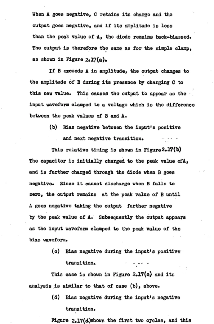
to clamp the input not to earth but to another voltage generator of the particular form shown in Figure 2.16. Both inputs are constant amplitude pulses, and for the purposes of explanation are of the same frequency, but
the clamp bias B has a smaller mark/space ratio than the
input A. Different clamping actions occur with this circuit depending on the relative timing of the input and bias.
(a) Bias zero between the input's positive and
negative transition.