iii
The strength and mechanical
behaviour of quartz slip interfaces
:
An experimental investigation
Kathryn Suzanne Hayward
August 2015
A thesis submitted for the degree of
Master of Philosophy
i
Declaration
The work in this thesis is my own except where otherwise stated.
iii
“Process is more important than outcomes. When the outcome drives the
process we will only ever go where we've already been. If the process drives
the outcome we may not know where we're going, but we will know we want to
be there."
-Bruce Mauv
Abstract
An experimental study has been undertaken to explore the strength, mechanical behaviour and microstructural evolution of bare interfaces in quartz sandstone during slip. These experiments were designed to simulate fault processes with increasing depth in the continental crust. Two main aspects have been explored: (1) the effect of temperature and confining pressure on the behaviour and stability of favourably-oriented faults, and (2) the influence of reactivation angle on the mechanical behaviour and associated microstructural evolution of a fault zone. Experiments were conducted on Fontainebleau sandstone using a triaxial deformation apparatus, at normal stresses comparable to that in the continental seismogenic regime and over small slip displacements.
The first suite of experiments was conducted at temperatures of 400-927°C and confining pressures of 50-200MPa. Experiments reveal complex transitions in fault behaviour between stick-slip and stable sliding regimes. Mechanical results are coupled with microstructural analysis using multiple techniques (including high resolution FE-SEM, and FIB-TEM) that provide insights into fault surface processes down to the nano-scale. Significant findings include the identification of a partially amorphous layer formed during aseismic creep and the generation of pure-silica frictional melt (pseudotachylyte) during high temperature seismic slip events. The pseudotachylyte is recognisable by the formation drawn-out glass filaments and fractured glass patches on the fault surfaces, forming a discontinuous layer up to 2µm thick and covering 10-60% of the fault surface. At normal stresses > 200MPa, frictional melt develops within the first 50µm of rapid slip, correlating with changes in slip acceleration and velocity. High temperature hydrothermal treatment of melt-covered fault surfaces indicates that the pseudotachylyte has a short lifespan (<1 hour) in the presence of high temperature, reactive fluids.
vi
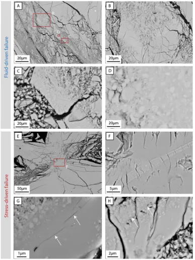
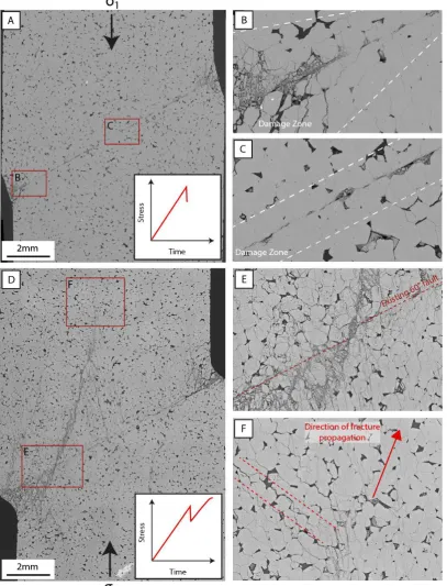
optimally-oriented to severely-misoriented for failure. These faults have been reactivated in both dry and fluid-saturated conditions, using two different loading mechanisms. ‘Stress-driven failure’ involves increasing the axial load at constant rate until failure, whereas ‘fluid-driven failure’ is achieved by maintaining a constant axial load and increasing pore fluid pressure until slip occurs. While the initial reactivation of faults obeys frictional theory, continued reactivation is strongly influenced by the microstructural evolution of the fault surface, most notably through the development of frictional melt. Rapid-slip events form a locally-continuous layer of frictional melt in both the dry and water-saturated samples. The presence of pseudotachylyte increases fault cohesive strength through a process termed ‘melt-welding’. Melt-welded regions serve as a nucleation point for the development of off-fault damage and on the most unoriented faults, cause lock-up and the failure of a new, more favourably-oriented fault.
vii
Acknowledgements
This thesis marks not only a milestone of academic learning but also, on more personal level, a change in career from working in the business sector to the beginnings of a journey into the earth sciences. Such a significant change cannot be achieved by one person alone and I am deeply grateful to all those that have contributed to this transformation.
My supervisor, Stephen Cox, is owed a special thank you, for not only for his role as supervisor, mentor and friend, but also for his courage in taking on a student with none of the requisite knowledge that most students possess when they enter their graduate studies. I consider it a privilege to have been guided by Stephen, and thank him for his patience, instruction, rigorous approach and for the inspiration that our many discussions have generated. I look forward to continuing to work with you into future, both on my PhD and beyond.
The first 15 months of this project was hampered by equipment issues as the deformation apparatus was resurrected from its experimental hiatus and a new digital data acquisition system was installed. Hayden Miller and the electronics and mechanical workshops are thanked for their wonderful technical support – often at very short notice. The rest of the rock physics group, including Mervyn Paterson, Ian Jackson, Emmanuel David, Christopher Cline, Yang Lee, Richard Skelton and Harri Kokkonen, are thanked for their assistance in the lab and also for the comradery and lively discussions over the past two years.
viii
Brink, Hua Chen, David Llewellyn and Felipe Kreme (Centre for Advance Microscopy), Lily Li and Mark Lockrey (Australian National Fabrication Facility) for the thorough training, assistance and interesting discussions about various aspects of electron microscopy and sample preparation.
I wish to thank Tim Senden, Michael Turner and Holger Averdunk from the department of Applied Mathematics at ANU for their assistance with the micro-computed X-ray tomography and subsequent data processing. Rhys Hawkins is thanked for his assistance with writing the Python scripts used for the thermal modelling.
A special thank you is also owed to Michelle Salmon for her encouragement, friendship and loan of, and assistance with the use of seismic equipment that is being used to better constrain slip duration. Bram Slagmolen, Perry Forsyth and Daniel Shaddock from the Department of Quantum Science are thanked for their wonderful help with the development of the laser interferometry system.
My thanks and gratitude also goes to the student body at RSES for the many discussions, laughs, and sharing the frustrations of failures when they occurred. A special thank you goes to Rhys, Shayne, Chris, Eleanor, Rachel, Marie, Johanna and Tanja.
ix
Contents
Chapter 1: Introduction ... 1
1.1 Frictional melting and the scarcity of pseudotachylytes on natural faults ... 3
1.2 Fault orientation and weakening mechanisms ... 4
1.3 Research aims and thesis structure ... 5
Chapter 2: Frictional melting on experimental quartz fault interfaces at elevated temperatures……….………...9
1. Introduction ... 9
2. Experimental method and analysis techniques ... 12
2.1 Experimental procedure and conditions... 12
2.2 Microstructural analysis techniques ... 15
3. Results ... 17
3.1 Mechanical behaviour ... 17
3.2 Optical and SEM microstructural analysis ... 21
3.2.1 Fault surfaces that have experienced stick-slip events ... 21
3.2.2 Stable sliding of fault surfaces ... 28
3.2.3 The effect of hydrothermal treatment after slip ... 30
3.3 TEM analysis ... 33
3.3.1 High velocity stick-slip events ... 33
3.3.2 Low velocity stick-slip events ... 43
3.3.2 Microstructures formed during stable sliding ... 45
3.3.2 Hydrothermally-treated fault surfaces ... 49
x
4. Discussion ... 51
4.1 Amorphisation on fault surfaces ... 51
4.1.1 Mechanisms for amorphisation ... 51
4.1.2 Influence of amorphisation on mechanical behaviour ... 52
4.1.4 Thermal modelling of fault surfaces ... 55
4.2 Coupling mechanical behaviour and microstructural evolution ... 62
4.3 A model for the formation of quartz melt ... 69
5. Conclusions ... 75
Chapter 3: Experimental insights into the mechanics and microstructures associated with the reactivation of misoriented faults………..79
1. Introduction ... 79
2. Experimental and analytical methods ... 82
2.1 Experimental methodology ... 82
2.2 Microstructural analysis techniques ... 86
3. Results ... 89
3.1 Mechanical behaviour ... 89
3.1.1 Mechanical properties of intact Fontainebleau sandstone ... 89
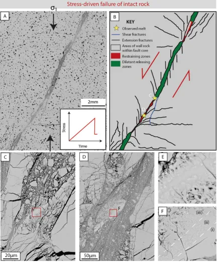
3.1.2 Stress-driven fault reactivation and failure ... 91
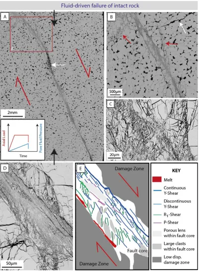
3.1.3 Fluid-driven fault reactivation and failure ... 94
3.2 2D Microstructural analysis using BSE-SEM imaging ... 95
3.2.1 Intact rock failure ... 96
3.2.2 Slip on existing fault surfaces ... 103
3.2.3 Hydrothermally-treated, reactivated fault ... 120
3.3 2D Microstructural analysis using high resolution SEM-CL ... 122
3.3.1 Stress-driven failure of unfavourably-oriented faults ... 124
xi
3.4 3D Microstructural analysis using microcomputed X-ray tomography ... 131
4. Discussion ... 136
4.1 Misoriented fault reactivation: A comparison with theoretical principles ... 136
4.2 Interpretation of microstructural processes ... 140
4.2.1 Amorphisation and the formation of frictional melt in nominally dry slip zones ……… 141
4.2.2 Formation of damage and frictional melting in a water-saturated environment ... 150
4.2.3 Development of new faults ... 156
4.3.4 Cathodoluminescence: insights and interpretation ... 159
5. Conclusions ... 163
Chapter 4: Frictional melt formation during crustal faulting: implications and future directions ……… 167
1. Dynamic changes on fault interfaces: implications for crustal faulting processes 167 1.1 Implications of amorphisation and frictional melting on the strength and mechanical behaviour of faults ... 170
1.2 Implications of identified fault slip behaviours in hydrous environments ... 173
1.3 Implication for the conditions and environments in which pseudotachylytes form ……… 175
2. Future research directions ... 176
2.1 Improved understanding of slip duration and evolution of slip velocities... 176
2.2 Quantifying real contact area ... 178
2.3 Constraining structural and chemical variation in the melt ... 178
2.4 Understanding mechanical amorphisation during aseismic slip ... 179
xii
2.6 Expansion of investigations to other rock types ... 180
2.7 Improved understanding of fluid-driven fault reactivation ... 180
2.8 Natural faults ... 181
3. Outlook... 181
References ………..…. 183
Appendix 1: Apparatus calibration and correction ………... 197
Appendix 2: Corrections for jacket strength contribution and change in contact area of the sliding interface ………... 205
Appendix 3: Starting material ……….. 221
Appendix 4: Summary of experiments ……… 227
1
Chapter 1
Introduction
Earthquakes are the result of shear mode failure of rock in a brittle regime. Most seismogenic ruptures in a continental setting occur in the upper 5-20km of the crust [Sibson, 1983], representing the zone of brittle failure and unstable frictional sliding that is, to a first order, governed by the empirical Coulomb failure criterion faulting. However, once slip nucleates, the behaviour of the fault is controlled by both dynamic weakening and strengthening mechanisms that either enhance or impede fault slip propagation. Despite having a crucial role in understanding fault rupture properties, including coseismic stress drop, energy radiation and heat production, dynamic fault strength remains a source of significant uncertainty in earthquake mechanics [Di Toro et al., 2006a].
The propagation of seismic slip is generally ascribed to the activation of dynamic fault weakening mechanisms at high slip velocities, which result in a significant deviation in frictional values from typical laboratory-derived static friction estimates of between
0.6 < 𝜇𝑠 < 0.85 [Byerlee, 1978]. Rate- and state-dependent friction laws have been
Introduction
2
The concept of dynamic fault weakening is supported by a number of observations from large earthquake ruptures, including: (1) unusually large stress drops associated with some earthquakes [Malagnini et al., 2010], (2) the lack of a pronounced heat flow anomaly associated with some major active fault zones (e.g., San Andreas fault [Brune et al., 1969; Lachenbruch and Sass, 1980]), (3) unusually large co-seismic slip displacements for some large earthquakes [Rodgers and Little, 2006; Fujiwara et al., 2011], and (4) the high seismic radiation efficiency of some earthquakes [Venkataraman and Kanamori, 2004]. Possible mechanisms for dynamic weakening have been explored both experimentally and numerically over the past fifteen years, especially with the advent of the high velocity friction apparatus and a proliferation of experimental studies [e.g., Hirose and Shimamoto, 2005b; Di Toro et al., 2006b; Han et al., 2011; Proctor et al., 2014]. Mechanisms such as thermal pressurisation [Sibson, 1973; Wibberley and Shimamoto, 2005; Rempel and Rice, 2006], silica gel lubrication [Goldsby and Tullis, 2002; Di Toro et al., 2004; Hayashi and Tsutsumi, 2010; Nakamura et al., 2012], dynamic activation / powder lubrication by gouge particles [Han et al., 2010; Reches and Lockner, 2010; Han et al., 2011; Siman-Tov et al., 2013], flash heating [Rice, 2006; Goldsby and Tullis, 2011], elasto-hydrodynamic lubrication [Brodsky and Kanamori, 2001], thermal decomposition [Han et al., 2007] and lubrication by frictional melting [Hirose and Shimamoto, 2005b; Di Toro et al., 2006a] have been proposed to produce in significant dynamic weakening (dynamic frictional values approaching 0.1). However, of these mechanisms, the production of pseudotachylyte or quenched frictional melt is the only mechanism that is definitively identified within natural fault zones and is regarded as the only unequivocal evidence in the rock record of the occurrence of seismic slip [Sibson, 1975; Kirkpatrick et al., 2009].
3
microstructures associated with the initial stages of fault weakening are rapidly overprinted and the identified effects of transient strengthening and weakening cannot be explored in terms of their direct effect on the promotion and termination of slip. In the case of dynamic weakening by melt lubrication, high velocity friction experiments have shown complex behaviour including a marked strengthening at the onset of melting. However, it remains uncertain how this behaviour changes at high confining pressures and realistic normal stresses [Fialko and Khazan, 2005]; further experimental investigation is needed to explore whether the strengthening associated with the onset of melting is sufficient to impede, or even terminate, some seismic ruptures.
1.1 Frictional melting and the scarcity of pseudotachylytes on natural faults
Earthquakes are associated with a rapid release of energy that is either dispersed in the form of radiated seismic energy [McGarr, 1999] or adsorbed along the rupture zone through mechanical work in the form of fracturing [Pittarello et al., 2008] and heat generation [Sibson, 1975]. A fundamental prerequisite for the generation of frictional melt is a high rate of mechanical work resulting in a rate of heat generation that exceeds the rate of heat dissipation [Di Toro et al., 2011]. However, examination of exhumed natural fault zones suggests that the formation of pseudotachylyte is rare [Sibson and Toy, 2006; Kirkpatrick et al., 2009]. This raises the possibility that frictional melting does not occur within all seismogenically active faults zones, or that pseudotachylyte forms at scales below standard microstructural observation (i.e. < 2μm), or that many pseudotachylytes are not preserved over geological timescales.
Introduction
4
significant energy expenditure through the formation of amorphous gels and the generation of nano-size gouge particles [Fondriest et al., 2013]. However, whether these wear products act as a precursor or inhibitor of frictional melting, and their influence on the macroscopic behaviour and stability of faults at realistic effective normal stresses remains largely unknown.
Although gels have been experimentally produced on the slip surfaces of faults during slip approaching seismic slip velocities [Hayashi and Tsutsumi, 2010], amorphous material has also been produced at comparatively low slip velocities (V<3µm.s-1) [Yund et al., 1990; Pec et al., 2012]. Accordingly, gel formation could potentially occur at any stage during the seismic cycle. Quartz and silica appear particularly susceptible to amorphisation processes [Heaney, 1994]. Intriguingly, despite quartz being a common mineral within fault zones in the continental crust, there are very few recorded examples of pure silica pseudotachylytes [Bestmann et al., 2011]. Whether this is a result of the high melting temperature of quartz [Navrotsky, 1994], weakening due to the presence of fluids, or due to the propensity of quartz to form amorphous gels that weaken the fault prior to the onset of melting, needs to be explored experimentally at realistic crustal stress conditions. Most high-velocity experiments undertaken on quartz-rich rocks (e.g., quartzite, novaculite and chert) have tended to form gels rather than frictionally melting, although novaculite has been shown to produce a high viscosity melt after approximately 0.4-0.6m of slip at 12.5MPa applied normal stress [Di Toro et al., 2006a].
5
1.2 Fault orientation and weakening mechanisms
The previous experimental work that has been discussed so far involves either uniaxial compression, direct shear arrangements or are ‘Andersonian’- type faults that are approximately optimally-oriented for reactivation. However, there is compelling geological evidence for the existence and reactivation of unfavourably-oriented faults that are inherited from previous deformation [Sibson, 1985, 1990b]. To reactivate these faults, by definition, they must be either frictionally weak or influenced by high pore fluid pressures [Sibson, 1990b; Cox, 2010]. Few experimental works have considered the reactivation of unfavourably-oriented faults [Jaeger, 1959; Handin, 1969; Mitchell et al., 2011], and even less work has been undertaken to investigate the influence of the high normal stresses on the microstructural evolution of the fault interface.
1.3 Research aims and thesis structure
From the preceding introductory discussion it is clear that a need exists for new experiments to span the experimental conditions between conventional low strain-rate rock shear failure experiments and high-velocity friction experiments undertaken on rotary-shear-type apparatus. This thesis combines (1) experimental work using the technical infrastructure of the Rock Physics Group at the Research School of Earth Sciences with (2) the novel application and use of high resolution imaging techniques to:
1. Explore the behaviour and stability of pre-existing sliding interfaces in a pure-quartz sandstone over a range temperature and pressure conditions.
2. Establish if there are identifiable differences in the slip velocities and acceleration of sliding instabilities during stick-slip behaviour at various pressure and temperature conditions and loading velocities.
3. Provide insights into precursory microstructures and phenomena associated with the early stages of seismic instability.
Introduction
6
5. Examine the role of low-temperature fluids on the reactivation of unfavourably-oriented faults, including their effects on the development of slip-related microstructures.
6. Investigate the longevity of slip-related microstructures during the interseismic period in the presence of hydrothermal fluids.
This thesis uses small displacement (<1mm) deformation experiments on bare quartz sandstone sliding interfaces to provide new insights into the behaviour and microstructural development of the fault surface during the early stages of seismic instability. The experiments are undertaken at confining pressures that are comparable to those of seismogenic depths in the continental crust (up to 250MPa) and are performed using an internally-heated, triaxial gas-medium deformation apparatus. An essentially pure quartz sandstone is used as the sample material with specimens configured with pre-ground bare interfaces to simulate the growth and development of faults where slip is highly localised. Two types of experiments are undertaken: the first suite presented in Chapter 2, involves high temperature (400-927ºC) reactivation of approximately optimally-oriented fault surfaces; the second set of experiments (Chapter 3) are undertaken at room temperature on faults oriented at between 25-70º to the shortening direction, representing faults orientations that range from optimally-oriented to severely-misoriented for reactivation.
The role of low-temperature fluids in modifying slip mechanics and microstructural evolution is also explored in Chapter 3. In this chapter, faults are reactivated in both dry and fluid-saturated conditions. Failure is instigated in two ways: the first involves the increase of axial load at constant rate until failure (stress-driven failure) and is undertaken at either nominally dry or water-saturated conditions; the second method involves reactivation of the fault by maintaining a constant axial load and increasing pore fluid pressure until slip occurs (fluid-driven failure).
7
9
Chapter 2
Frictional Melting on Experimental Quartz
Fault Interfaces at Elevated Temperatures
1.
Introduction
solid-Frictional Melting on Quartz Interfaces
10
state processes, the conditions of fault rupture can be very different and potentially occur at sub-seismic slip rates [Pec et al., 2012].
Our understanding of the processes involved in the development of fault weakening behaviour and pseudotachylite generation has progressed rapidly over the past 15 years with extensive experimentation, primarily on high velocity rotary shear apparatus [e.g. Shimamoto and Tsutsumi, 1994; Di Toro et al., 2006a; Proctor et al., 2014]. Many advances have been made in understanding high-velocity friction and dynamic fault weakening, with such behaviours being attributed to mechanisms such as flash heating of asperities [Rempel, 2006; Goldsby and Tullis, 2011], thermal pressurisation [Sibson, 1973; Rice, 2006], intense comminution [Han et al., 2011], frictional melting [Spray, 1995; Di Toro et al., 2006a; Nielsen et al., 2008], and the formation of amorphous silica-gels [Goldsby and Tullis, 2002; Di Toro et al., 2004; Hayashi and Tsutsumi, 2010; Nakamura et al., 2012]. While the high velocity rotary shear apparatus allows exploration of velocities approaching seismic slip rate rates, the low normal stresses (< 97MPa [Proctor et al., 2014]) and unrealistically high displacements (> 0.5m, but commonly between 20-100m [e.g. Goldsby and Tullis, 2002; Di Toro et al., 2004; Hirose and Shimamoto, 2005b]) potentially place limitations on the extrapolation of the observed phenomena to crustal faulting conditions. Comparison of observations from high velocity shear experiments with those performed on a triaxial apparatus under high confining pressure can provide a point of correlation between the preliminary behaviours and microstructures marking the onset of dynamic weakening and fault rupture.
11
hydrated amorphous gel during high velocity sliding alludes to some of the specific material properties of this mineral, including the ability to modify its crystal structure under different pressure-temperature conditions resulting in numerous polymorphs [Heaney, 1994] and, almost conversely, the ability to lose its long range crystal order to become amorphous at high pressure (when the rate of damage of the crystal lattice exceeds the rate of growth of the new stable crystalline phase) [Winters et al., 1992; Badro et al., 1998], during shear [Yund et al., 1990; Di Toro et al., 2004; Nakamura et al., 2012] and at high temperature. In the current context of pseudotachylite generation, where stress and temperature states are extreme and dynamic, the ability of quartz to transition between phases and crystalline-amorphous states brings into question whether quartz pseudotachylytes are rare [Sibson and Toy, 2006], or whether the amorphous silica and glass are poorly preserved [Kirkpatrick et al., 2009], reverting to a more stable crystalline form or being overprinted by such processes as hydrothermal alteration and recrystallization. The difficulty of experimentally producing a quartz melt may also simply be a consequence of experimental set-up with the majority of pseudotachylite research being undertaken at low normal stresses and ambient temperatures.
Frictional Melting on Quartz Interfaces
12
or localised melting can be correlated with the observed physical and mechanical phenomena.
2.
Experimental method and analysis techniques
2.1 Experimental procedure and conditions
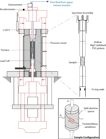
The experiments performed in this study are undertaken on pre-ground Fontainebleau sandstone fault interfaces that are in direct contact (i.e. there is no layer of simulated gouge material between the fault surfaces). Fontainebleau Sandstone is an approximately equigranular, almost pure quartz sandstone with grain size between approximately 200-250µm and a porosity between 6-8%. This sandstone has been consolidated by the formation of syntaxial overgrowths in a silica-supersaturated solution [Thiry et al., 1998; Haddad et al., 2006], resulting in a subhedral to euhedral grain shape. The quartz grains contain numerous fluid inclusions that are observed to occur both within the detrital grains or decorating healed intragranular fractures and overgrowth boundaries. The distribution of the fluid inclusions is heterogeneous making up between 0.01 – 0.1 vol. % of the crystalline material within sample, with an average inclusion size of ~1.1μm3. The fluid inclusions contain multiple phases, with H2O(Liquid +
Vapour), CO2 (Liquid) and small daughter crystals in a number of the locations but
dominantly within the detrital grains indicating formation during petrogenesis. Given the coastal depositional environment and subsequent shallow burial of the Fontainebleau sandstone [Thiry et al., 1998], it is assumed that most post-sedimentation fluid inclusions also contain at least some free water. The presence of water is supported by a small spike in the Raman spectra at 3420 (cm-1), however the size of the inclusions are too small to allow a more robust spectral analysis.
13
deformation, a correction for the strength contribution of the metal jacket assembly has been applied (refer to Appendix 2).
Experiments were undertaken in a Paterson internally heated, gas-medium, rock deformation apparatus that permits the independent control and measurement of temperature, confining pressure (Pc), pore fluid pressure (Pf), axial displacement rate
and axial load [Paterson, 1970]. This device is considered a ‘soft’ apparatus, as it accumulates significant elastic strain during loading that can be imparted to a specimen during failure, resulting in significantly higher displacements and stress drops than could be achieved using a more rigid apparatus. The experiments were conducted over a range of temperatures from 500-927ºC, Pc between 50-200MPa and a nominal axial
displacement rate between 0.36-0.72μms-1. Data was recorded using a digital data acquisition system (National Instruments LabView 11.0) with a sampling frequency of 100Hz and recording frequency of 1Hz.
Frictional Melting on Quartz Interfaces
[image:29.595.58.508.71.662.2]14
Figure 1: Schematic illustration of deformation apparatus and sample configuration
15
The longevity of the pseudotachylite in its vitreous form was explored by completing a number of experiments involving isostatic pressing of the slipped sample over a range of experimental conditions in both dry and hydrothermal conditions. To investigate the potential crystallisation of the melt in nominally dry conditions, the axial load was removed and the temperature set at 700º following a large stick-slip event for between 1- 6 hours. This temperature was chosen as it is comfortably within the stability field of β-quartz at the given confining pressures.
To explore the stability of the pseudotachylite in a hydrous environment, two experiments were performed where pore fluids were added following the melt-producing slip event. During these experiments, the axial load was removed following the slip event and the temperature and confining pressure were reduced to T = 25°C and Pc≈ 40MPa. Deionized water pore fluid was then introduced via the upper hollow
ceramic (MgO stabilized PSZ) pistons before the temperature and confining pressure were concurrently increased. Approximately 20 minutes prior to the desired conditions being attained, the pore fluid pressure was gradually increased until the hydrothermal isostatic pressing (HTIP) conditions of 500-900ºC, Pc=250MPa and Pf=150MPa were
attained. The pore fluid was introduced in this way to ensure that a sufficient effective confining pressure was maintained to preserve the integrity of the assembly seals and to keep the reaction time between the pore fluids and pseudotachylyte constrained as much as possible to the HTIP period of 1 hour.
2.2 Microstructural analysis techniques
The morphology and structure of the slipped surfaces where investigated using a range of techniques including reflected light microscopy, scanning electron microscopy (SEM), transmission electron microscopy (TEM) and x-ray diffraction (XRD). To prepare the slip surfaces for optical and SEM analysis, the jacket and sleeve surrounding the experimental sample were dissolved in concentrated nitric acid. The two halves of the fault were retrieved and carefully rinsed in water, dried and mounted in a custom sample holder for examination by secondary electron SEM. To achieve the highest resolution during imaging whilst minimising charging, the fault surfaces were sputter coated with platinum.
Frictional Melting on Quartz Interfaces
16
was commonly observed to have a spherulitic texture suggesting rapid growth from a liquid, with many of the fine gouge particles serving as crystallisation nucleation points. Consequently, the sample preparation technique was modified to avoid sample – acid contact. For experiments undertaken at temperatures below approximately 700°C the iron jacket and copper sleeve were not bonded and the jacket and sleeve were individually peeled off with great care taken to prevent disturbance of the fault surfaces. For experiments undertaken at higher temperatures, the iron jacket was dissolved in nitric acid and then the inner copper sleeve was manually peeled from the sample. Fault surface textures were analysed using the in-lens secondary electron (SE) detector of the high resolution Zeiss UltraPlus field emission SEM (FE-SEM). Working conditions of 3.0-5.0kV accelerating voltage, a 10μm objective aperture and a working distance between 3-5mm allowed an imaging resolution of less than 10nm.
17
the SIEMENS software package Diffracplus Eva 10 (2003) which uses the PDF-II database provided by the International Centre for Diffraction Data.
The use of Raman spectroscopy was also attempted to gain an understanding of the composition and structure of the fault wear products, but the laser beam intensity that was required to produce a signal was higher than the sample could support without damage.
3.
Results
3.1 Mechanical behaviour
Thirty optimally oriented, high temperature (T=400-950°C), nominally dry bare interface fault experiments were completed over a range of confining pressures (Pc
=50-200MPa) and axial displacement rates (a summary of which is provided in Appendix 4). The results reveal a surprisingly complex range of mechanical behaviours with a number of behavioural transitions (Fig. 2A) being observed with changes in temperature and confining pressure. Experiments were undertaken at regular intervals of temperature and confining pressure to better understand and bracket the observed transitions in behaviour.
Frictional Melting on Quartz Interfaces
[image:33.595.86.444.60.656.2]18
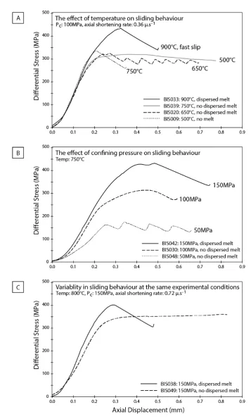
Figure 2: Representative mechanical behaviour of faults over a range of experimental conditions.
19
averages ~0.7 during the lower temperature stable sliding experiments. These results are comparable to other frictional sliding experiments undertaken a slow slip rates (<0.1mm.s-1) [Byerlee, 1978].
A comparison of experiments undertaken at comparable confining pressures reveals a systematic increase in shear strength (calculated from peak stress prior to the first stick-slip event, if relevant) with increasing temperature, from approximately 128MPa at 400°C to 161MPa at 927°C (Fig. 3A). Undertaking a least squares linear regression of the experimental data supports this observation with a positive correlation being observed between peak shear strength and temperature (𝑑𝑑
𝑑𝑑 = 0.061 ± 0.025MPa/°C
including all data, and 𝑑𝑑
𝑑𝑑 = 0.065 ± 0.011MPa/°C with outliers removed; uncertainty
is reported at one standard deviation). However, this result is somewhat biased given the limited number of experiments performed at lower temperatures. The faults that exhibit stick-slip behaviour generally have a higher peak strength, although there are a couple of notable exceptions: first, BIS027 (Pc=100MPa T=800°C) was characterised by an
anomalously low peak strength and experienced significant slip weakening prior to failure; and second, BIS026 (Pc=100MPa T=900°C) experienced an initial small stress
Frictional Melting on Quartz Interfaces
[image:35.595.62.502.65.423.2]20
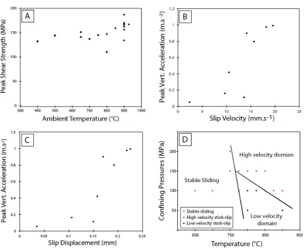
Figure 3: Relationship between experimental conditions and mechanical behaviour.
(A) Comparison of experiments at Pc=100MPa showing the relationship between increasing temperature
and peak shear strength. (B) Relative peak vertical acceleration during the first stick-slip event is plotted against slip velocity showing the distinct difference between high apparent acceleration and velocity and low apparent acceleration and velocity. (C) Peak vertical acceleration is plotted as a function of slip displacement showing the strong correlation between high peak acceleration and large slip displacements. (D) Identification of regions of different sliding behaviours as a function of confining pressure and temperature. Note the occurrence of stable sliding at high confining pressures and temperatures.
21
peak strength prior to subsequent stress drops increasing with continued displacement. Similar observations were made for experiments undertaken at comparatively high confining pressures (Fig. 2B), although the larger stress drops and higher displacement in this case may be partially associated with the increased stored elastic strain in the apparatus.
A number of experiments (notably BIS037 and BIS049) showed differences in sliding behaviour at the same experimental conditions (Fig 2C). It was found that in the temperature range from 650-800°C with increasing confining pressure, both stick-slip and stable sliding behaviours were activated, suggesting the possibility that a transition to stable-sliding behaviour may occur at higher confining pressures (Fig. 3D).
3.2 Optical and SEM microstructural analysis
3.2.1 Fault surfaces that have experienced stick-slip events
Frictional Melting on Quartz Interfaces
22
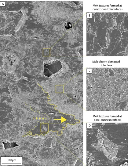
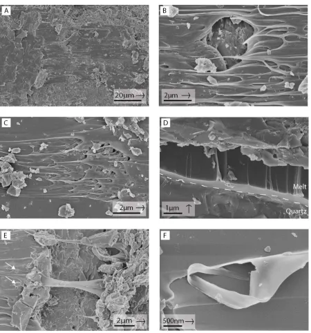
Compositional analysis (energy dispersive analysis of X-rays) of the melt layer by both SEM and TEM-EDS indicates that it is comprised essentially of pure silica with impurities being below limits of detection. The microstructure of the dispersed film is consistent with a highly viscous siliceous melt. There is limited evidence of lateral extrusion with melt patches forming lobate flow fronts and no evidence of flow into adjacent pores. Many regions are characterised by the formation of long ribbon-like glass filaments (see esp. Fig. 5), thought to be formed when melt adhered to the sliding surfaces is drawn apart during sliding, forming a toffee-like shear sense indicator. In some cases, the glass filaments have snapped while still soft, forming nanometre scale curls and folded pieces of glass (Fig. 5B & F). Other flow textures form striations ranging in length from a few microns to in excess of 150μm (Fig. 4A, 7A).
Occasional fracturing and removal of part of the melt surface during sample recovery, reveals that the thickness of the melt layer is between ~1-2µm (Fig. 5D). The surface of the melt is locally vesicular and SEM imaging indicates that gouge particles are rarely present in the melt. In particular, the striated upper surface of the melt is generally smooth and free of incorporated clasts. Where clasts (ranging in size from 20nm-1µm) are present, they are rounded; many have mantled tails of melt forming linear flow textures parallel to the slip direction (see arrows, Fig. 5E). Locally the melt layer has the appearance of a holey film with glass filaments being drawn off gouge particles (Fig. 5C).
23
Figure 4: Overview of fault surface showing characteristic microstructures.
Frictional Melting on Quartz Interfaces
[image:39.595.57.508.67.550.2]24 Figure 5: Melt structures on fault surfaces.
Secondary electron SEM images of melt structures on slip surface in BIS010, slipped at 900ºC,
Pc=100MPa. Arrows indicate slip direction of the imaged fault block. (A) Overview of an area on the
25
Figure 6: Fractured patches of amorphous material without flow structures.
Frictional Melting on Quartz Interfaces
26
the outline of the shape of the asperity or grain on the opposite surface (see arrows, Fig. 6B). Additionally, vesiculated regions within the fractured glass patches typically have vesicles elongate in the direction of slip, thus indicating viscous shear occurred within the melt (Fig. 6D). Glass patches formed during the small stress drop, low velocity slip events (Fig. 6E-F) have a similar habit to those of the high velocity slip events, although the ribbon-textured melt domains (i.e. glass filaments, flow textures etc.) are absent and there is no indication of viscous shear within the patches (e.g. elongate vesicles).
The preservation of delicate melt structures on the rupturing fault surface suggests that melt forms at asperity contacts and is then transported by the shearing surfaces to regions adjacent to pores. The formation and preservation of these melt flow structures provides unique insights into the timing relationships of slip and melt formation. Many of the striated melt-covered surfaces preserve continuous linear flow structures in excess of 150µm long, providing unequivocal evidence of continuous slip on a melted fault surface for the majority (~70%) of the displacement recorded during the rapid slip event (Fig. 7A).
The formation of evenly spaced fractures and indentation marks within the glass layer in close proximity to clasts (Figs. 7B-E) suggest the formation of chatter marks [cf. Doblas, 1998] and similarly provide insights into the timing of melt formation. These chatter marks display textures indicating varying degrees of melt viscosity at the time of formation, ranging from molten (Figs. 7B-C) to dominantly brittle (Fig. 7E). The interaction of clasts with less viscous melt (Figs. 7B-C) is commonly characterised by the formation of a ‘bow-wave’ of melt around the front of the clast, accretion of melt onto the clast and the development of a melt-imprinted trail. In comparison, the chatter marks produced on a more viscous surface (Fig. 7E) have left a trail of evenly spaced, semi-brittle fractures inclined in the direction of the clast movement and have an inferred depth and aperture of approximately 200nm. Some chatter marks exhibit both brittle and viscous deformation features (Fig. 7D) and may arise from variations in melt temperature and potential strain-rate dependence of melt deformation.
27
Figure 7: Microstructural insights into the timing relationships between production of melt and slip.
Arrows indicate direction of slip of the imaged surface. (A) BIS043 overview of fault surface showing
Frictional Melting on Quartz Interfaces
28
Drawn out delicate ribbon-like filaments (diameters < 20nm) indicative of melt stretching, form within the extensively damaged and fractured zones associated with the production of gouge (see arrows, Figs. 8A-C). This raises the possibility that melting occurs locally late in the slip event, overprinting a previously damaged substrate. Significant heating between impinging gouge particles is thought to form these occasional areas of melt.
The quartz substrate in areas immediately adjacent to the melted regions is generally extensively damaged with closely spaced arrays of extension fractures forming orthogonal to the sliding direction and inclined at an acute angle to the slip surface, opposite to direction of motion of the fault block. That is, the fractures dip towards the direction of motion of the opposite fault block, making them a reliable shear sense indicator. These fractures could be the result of both thermal and mechanical processes arising from intense localised temperature gradients, coupled with the substantial dynamic stresses associated with fault slip (Figs. 4-7). The fractures are between 1-3μm in length and spaced between 200nm-1μm apart, forming an extensively damaged surface. Despite this fracturing many of these regions lack surficial wear products (e.g. Fig. 4C).
Where gouge is present on the fault surface, the particles appear to have developed initially as small slivers aligned parallel to the micro-cracks and perpendicular to the direction of slip, resulting in large areas of similarly oriented particles (Fig 8D-E). During subsequent slip many fragments are crushed and rotated, forming areas of irregularly oriented gouge particles ranging in size from <100nm-2µm (Fig. 8F). The volume of gouge on the fault surface positively correlates with increasing aseismic displacement prior to the fault rupture and rapid stress drop. The fault surfaces of experiments that have produced low-velocity slip events also show an increase in the abundance of fragments compared with the gouge produced in experiments where distributed melt is also formed.
3.2.2 Stable sliding of fault surfaces
29
Figure 8: Microstructure of gouge and mechanisms for gouge production on fault surfaces.
Frictional Melting on Quartz Interfaces
30
with the copious generation of fragments. However, microscopic analysis identifies a range of phenomena that could be either precursory to the microstructures identified in the stick-slip experiments or associated with the development of amorphous material on the fault interface (Fig. 9). Cylindroidal structures present on the slip surface are elongate perpendicular to the direction of slip, and have a morphology indicative of formation as either agglomerated rolls of particles (Fig. 9A-B) or as a rolled film-like structure (see arrows, Fig. 9E). Flaky patches of densely packed, fine-grained material with an overall diameter between 10-25µm are also present on the fault surfaces (Figs. 9C-D and G-H). These structures differ from both the crystalline quartz substrate and the glass patches (formed during stick-slip events) described in Section 3.2.1. At the larger scale these smooth texture zones are characterised by lobate edges and surfaces decorated by slickenlines. Examination at higher magnification densely packed particles bound together in a possibly melt-like matrix (Fig. 9H). Many of these regions exhibit chatter marks similar to those observed on the partially quenched melt surfaces.
Although not unique to stable sliding experiments, a number of samples have ‘negative crystals’ (see arrow, Fig. 9F). These are interpreted to represent fluid inclusions in the starting quartz crystal that, during hot pressing and deformation, have re-equilibrated to the most stable surface energy state for the inclusion [Van den Kerkhol and Hein, 2001]. During SEM imaging the negative crystals are often localised or form on a linear trace, appearing to be generally sub-micron in size and having varyingly developed faceted surfaces. The best developed negative crystal shapes are present in the high temperature or long duration experiments, supporting the interpretation that the fluid inclusions have re-equilibrated during the experiment. These fluid inclusions potentially provide a fluid source for the formation of vesicles present in the melt layers of stick-slip experiments.
3.2.3 The effect of hydrothermal treatment after slip
31
Figure 9: Microstructures from faults that did not experience stick-slip or did not produce visible melt.
Frictional Melting on Quartz Interfaces
32
treated samples, suggest either residual areas of melt or zones of minimal topography formed by quartz precipitation. SE-SEM analysis of the fault surfaces (Fig. 10) also reveals a dramatic change in microstructure compared with the melt-related textures of an untreated sample. There is no distinguishable evidence of melt remaining on slip surface at the conclusion of either experiment, however on the high temperature HTIP sample some surfaces have developed stepped edges producing polyhedral faceted surfaces (Fig. 10A). The variability of the orientation of the stepped edges between grains suggests that these structures are crystallographically controlled.
Features on the fault surface of BIS028 (500°C HTIP) are more easily correlated with the microstructures in the dry slip experiments. Areas that could be melt-generation surfaces appear to be free of melt; remnants of fractures and slickensteps that are characteristic of the crystalline substrate form approximately linear features perpendicular to the slip direction (see arrows, Fig. 10C). However, these surfaces are also characterised by textures that are very different from the untreated samples. Lobate domains are interspersed with fine (< 1μm) rounded particles that commonly display euhedral faces (Figs. 10C-D). Lineations are parallel to the slip direction and are often recognised by changes in topography of the lobate domains. On the submicron scale many of small (<200nm) particles are observed to be embedded and almost enveloped in the smooth, but occasionally faceted surface (Fig. 10E). The rounding of edges and formation of euhedral surfaces on small grains, together with etching along fractured surfaces and the development of the stepped polyhedral faceted surfaces on the high temperature (900°C) sample, indicate the activation of dissolution-precipitation processes during the hydrothermal treatment. Further evidence of the activation of
Figure 9 continued.
33
dissolution-precipitation process occurs on the nano-scale where grain interface structures are visible where gouge particles have been dislodged during sample preparation. The interface structures include ridge and plateau features [cf. Cox and Paterson, 1991] that have the semblance of silica precipitation locally surrounding flat bottomed interfacial pores (Fig. 10F, see arrows). More common, however, are the smooth faced dissolution pits or depressions caused by the impingement of grains during HTIP.
The finest fraction of the gouge particles are absent from the HTIP sample. This reflects the rapid dissolution of the fine particles due to their high solubility (Ostwald Ripening) [Steefel and Van Cappellen, 1990]. The changes in grainsize are very temperature dependent, with the largest changes being observed in the 900° HTIP sample, where the gouge particles <1000nm have been removed in contrast to the 500°C experiment in which particles <100nm are absent. Many of the remaining gouge particles have lost the angular appearance that is characteristic of gouge in the dry sliding experiments (Fig. 8F), instead becoming rounded and/or developing euhedral surfaces (Fig. 8E-F). The formation of small quantities of platy minerals is also noted. These possibly reflect a reaction between the pore fluid and copper jacket forming copper (II) oxide (CuO).
3.3 TEM analysis
Eight samples for TEM analysis were prepared using ion beam milling in a FIB-SEM. This method of producing TEM foils proved to be extremely useful for analysing cross sections of the fault zones and facilitating comparison of microstructures across a range of scales. The FIB milling process provides a 10-15μm long and 4-5μm wide cross section of a targeted feature on the fault surface, thus providing subsurface information about microstructures identified in the SEM (refer to Appendix 5). In the following section microstructural observations from the FIB sections are described.
3.3.1 High velocity stick-slip events
Frictional Melting on Quartz Interfaces
34
Figure 10: The effect of hydrothermal isostatic pressing on melt covered surfaces.
SE-SEM images of microstructures on fault surfaces. All images have a vertical slip direction. (A-B) BIS024: HTIP at 900°C for 1 hour. (A) Etched crystal on the fault surface. (B) Note the absence of the
gouge fraction <1μm in diameter. Remaining larger grains are also more rounded when compared with
the dry gouge particles (Fig 7). (C-F) BIS028: HTIP at 500°C for 1 hour. (C) Area assumed to be an originally melt-bearing surface prior to HTIP. Fractures formed perpendicular to the slip direction are exposed and etched. (D) Detail of HTIP surface showing domains of lobate textures. (E) Finest fraction of the gouge material is absent (grains <100nm). The grains have become much more rounded in comparison with samples that have not been HTIP and many of the grain surfaces are developing euhedral faces. Note that many of the smallest residual grains are almost enveloped by overgrowth of the underlying quartz (wall-rock) substrate. Fine grained material on the right hand side of the image is thought to be silica precipitated during quenching. (F) Rounded grains, euhedral faceted surfaces and
ridge and plateau structures [cf. Cox and Paterson, 1991] on exposed surface of a grain-to-grain contact
35
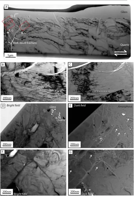
material is recognised in bright-field mode by the absence of Bragg diffraction contours and its uniform, unchanging contrast. The amorphous structure was confirmed by selected area electron diffraction (SAED), which shows a broad diffuse ring around the central transmitted beam, reflecting the lack of long-range crystalline order within the sample (Fig. 11A and 13C). For samples BIS010 and BIS035 this amorphous layer corresponds to the striated quenched-melt film that is visible on the surface of samples during SEM analysis. The sections from sample BIS043 (Figs. 13 - 14), were milled in locations characterised by fractured, debris-free melt patches on the fault surface. FIB Section 4 (Fig. 14) was milled across the boundary between the fractured melt patch and a region exhibiting melt flow textures. The presence of the amorphous layer on this sample adds weight to the supposition outlined in the Section 3.2.1 that this area represents melt between two asperities, and that has fractured after quenching.
Frictional Melting on Quartz Interfaces
36
Figure 11: FIB Section 1, BIS010 – High velocity slip experiment cut perpendicular to the slip direction.
37
sample tilting with the objective aperture in place, signifying diffraction by crystalline material. The SAED pattern is characterised by diffraction spots in a broader band of diffuse electron intensity that is consistent with multiple crystalline grains in an amorphous matrix (Fig. 11C).
FIB Section 3, milled from BIS043, contains a larger number of clasts than the other sections, with many having angular shapes. A number of the larger clasts are laced by a network of melt-filled fractures (see arrows, Fig. 13C). The angularity of the crystalline fragments indicates that the clasts are gouge particles that have been incorporated into the melt. The angularity may indicate that grains have not significantly melted. In contrast, in Section 6 from BIS035 (Fig. 15C), a region within the amorphous layer contains very fine quartz crystals (diameter between ~5-50nm) that are rounded in appearance, possibly signifying incorporation by the melt prior to quenching. This sample was hot pressed under isostatic conditions for 6 hours at 700°C following slip. The lack of euhedral shapes implies that these crystals did not nucleate from the silica glass during hot pressing. The absence of devitrification textures such as spherulites shows that in dry experimental conditions, the melt is relatively stable over the time frame of the hot pressing.
The sharpness of the glass - quartz substrate boundary is notable (e.g., Fig.11 and Fig. 15), with many (see black arrow, Figure 11E) being less than 10nm wide. Such boundaries are consistent with observations made of melt-crystal interfaces during thermal induced melting [Dell'Angelo and Tullis, 1988].
Frictional Melting on Quartz Interfaces
38
Figure 12: FIB Section 2, BIS010 – High velocity stick-slip event cut parallel to slip direction.
39
determined in bright-field imaging by the similarity of electron intensity between different grains within an region when the objective aperture is in place.This and other similar fragmented material may be a source of gouge particles that become entrained within the melt.
The crystalline quartz substrate in all FIB sections is recognisable in bright-field TEM images by Bragg contours corresponding to highly variable image intensity. The differences in contrast between grains relates to variations in crystal orientation and/or to sample thickness. Holes, fluid inclusions and pores appear as light grey to white, corresponding to lower scattering of electrons resulting from the reduced thickness of crystalline quartz. The SAED patterns confirm the crystallinity of the quartz substrate (e.g., Fig. 11D). The microstructure of the quartz substrate is complex, with extensive fracturing and other deformation-related microstructures such as dislocations, subgrains, and healed micro-fractures (Figs. 11-15). These complexities reflect microstructures from both the current experimental deformation, and also from the previous deformation history of the clasts forming the Fontainebleau sandstone (refer to Appendix 3). However, for the purposes of this study the main focus is on the microstructures associated with amorphisation and the amorphous-crystalline interface, so only brief observations are made regarding the crystalline substrate.
Frictional Melting on Quartz Interfaces
40
Figure 13: FIB Section 3, BIS043 – High velocity stick-slip experiment cut parallel to the slip direction on a fractured area with no visible melts textures.
During milling it was apparent that there was fracture or plane of weakness ~1.7μm beneath the surface of
41 as extension veins during fault slip.
Variable densities of dislocations are present within the crystalline substrate of the samples, as expected given the presence of undulose extinction in the starting material (see Appendix 3). Localised dislocation arrays are accompanied by a high density of fluid inclusions (see arrows, Fig 15E). These dislocations are interpreted to have developed along healed micro-cracks [cf. Fitz Gerald et al., 1991] in the quartz prior to erosion and incorporation of clasts in the Fontainebleau sandstone, rather than during experimental deformation.However, the crystalline substrate of FIB Section 4 (Fig. 14) is characterised by the formation of parallel linear defects in the ~2μm adjacent to the melt interface. TEM analysis indicates that these structures are dislocation lines and their approximately straight orientation suggests that they are restricted to their glide planes, forming parallel to (0001).
Dark-field imaging of the crystalline substrate in areas where the dislocations have formed shows the presence of amorphous material within fractures (Fig. 14E,G). Brittle deformation of this region of the substrate also appears to be controlled by crystallographic orientation, with consistently oriented fractures assumed to be forming parallel to a plane (not identified) of weakness within the crystal. The morphology of the melt-substrate interface and the formation of gouge fragments within the melt layer are governed by the geometry of the defects, with melt invasion of these sites forming stacked blocks of similarly oriented crystals making up the gouge (Fig. 14D). The change in orientation of the upper 1-2 clasts (shown by a change in diffraction intensity relative the rest of the sequence) implies the beginning of rotation and entrainment of the clasts within the shearing melt layer.
Frictional Melting on Quartz Interfaces
[image:57.595.56.506.59.722.2]42
Figure 14: FIB Section 4, BIS043 – high velocity experiment cut parallel to slip direction on an boundary between striated melt textures and a fractured, debris free patch.
43
amorphous material within area B (Fig. 13) and also weak crystalline spots. Porosity is variable within the substrate of this sample with higher porosity regions being located either adjacent to clasts or away from the glass-substrate boundary.
3.3.2 Low velocity stick-slip events
A FIB sample was milled into a fractured, debris-free patch on the surface of BIS041 (Pc = 50MPa, T = 900°, Fig. 16), which is a sample that experienced a small
displacement (106μm) slip event. SEM analysis of the slip interface had shown no visible signs of melt flow textures, other than the fractured, glass-like debris-free patches (Fig. 6E). However, TEM of a cross section of the fault zone uncovers many of the first-order features that are present in the high slip velocity samples, including an approximately 600nm wide amorphous layer between the fault surface and the crystalline substrate. Compositional analysis of the amorphous material using TEM-EDS reveals that the material is essentially pure silica, with other detected elements being attributable to contamination associated with FIB sample preparation (such as gallium and platinum; for analysis locations see red dashed circles, Fig. 16).
Comparatively more clasts occur within the amorphous layer of this FIB section than occur in the high slip velocity samples described in Section 3.3.1, with clasts ranging in size between <10nm to 200nm. A number of the clasts exhibit textures indicative of
Figure 14 continued.
Frictional Melting on Quartz Interfaces
44
Figure 15: FIB Section 5, BIS035 from high velocity slip experiment cut parallel to slip direction and perpendicular to slip surface; hot-pressed for 6 hours following slip.
45
partial melting, including embayed margins and the development of incipient melt veins within the entrained clast. In topographically lower regions of the amorphous-crystalline interface, a number of pockets of gouge remain, while in contrast, other regions of the interface are characterised by a sharp, debris-free boundary. In many locations within the amorphous layer, the crystalline gouge particles are irregularly distributed, whereas in other areas the clasts occur in clusters and form trails of particles approximately parallel with the melt-substrate boundary (see dashed lines, Fig. 16F). The absence of microstructures such as elongate vesicles or melt-flow textures indicating viscous flow suggests the possibility that these debris trails may not be a shear-related feature, but instead may represent features such as grain-size variation in the fault zone prior to melting.
Within the melt layer are a number of fractures oriented parallel to the melt formation surface (e.g., Fig. 16A, F). These fractures possibly form as a result of local tensile stresses within the glass layer during quenching, unloading or decompression. Intense fracturing is also observed in a clast at the slip interface, resulting in the formation of closely-spaced (<50nm) parallel fractures (see arrows, Fig. 16F) orientated at a high angle (~90º) to the slip surface, again suggesting possible crystallographic control. These fractures contain amorphous material as shown by the lack of contrast change during specimen tilting in bright-field mode; the presence of amorphous material could arise from either melt injection or from preferential melting along the fracture boundaries. Regardless, such fractures must have formed during slip activity.
3.3.2 Microstructures formed during stable sliding
A TEM foil was milled perpendicular to the slip surface and parallel to the slip direction of BIS037 (Pc = 150MPa, T = 800°, Fig. 17) in an area where densely-packed particles
Frictional Melting on Quartz Interfaces
46
Figure 16: FIB Section 6, BIS041 - Low velocity stick-slip experiment cut perpendicular to the slip surface and parallel to slip direction.
47
increasing away from the principal slip zone. A few much larger, fractured, but unrotated grains occur close to the undamaged substrate and have a diameter of approximately 0.5μm.
During high resolution SEM imaging, the morphology of the lineated patches pointed to the formation of a non-crystalline matrix, recognisable by its film-like properties. However, TEM analysis of the fine-grained quartz within the gouge zone proved difficult due to the relative thickness of the sample (~100nm) compared with the size of gouge particles and potential for overlap of fragments and pores. For this reason identification of potentially amorphous material was extremely difficult using bright-field imaging and consequently dark-bright-field imaging was employed [cf. Yund et al., 1990]. In dark field mode, potential amorphous material is found to have an intermediate contrast between the bright crystalline gouge fragments, whose reflections fall within the objective aperture, and the low intensity of the crystalline material whose reflections fall outside the aperture. Comparative bright-field and dark field images are shown in Figure 17(B-E).
Frictional Melting on Quartz Interfaces
48
Figure 17: FIB Section 7, BIS037– Aseismic creep experiment cut perpendicular to the slip surface and parallel to slip direction.
49
3.3.2 Hydrothermally-treated fault surfaces
A TEM foil was milled on the surface of BIS028, an experiment involving hydrothermal treatment for 1hr at 500ºC following melt-inducing slip. The area that was chosen was one of the regions interpreted as a melt generation surface on the basis of SEM analysis, which indicated the presence of linear fractures perpendicular to the slip direction, as well as lobate domains interspersed with fine particles (e.g., Fig. 10C-D). Unfortunately this foil represents far from ideal sample preparation with the platinum coat and small particles separating from the substrate.
TEM imaging indicates the sample surface has a microstructure very different from the slip surfaces that had not been hydrothermally treated. Fractures and other fault surface damage appear to have largely healed during the 1 hour of hydrothermal treatment. The partially healed fractures are decorated by trails of elongate fluid inclusions which range in size from <5nm-70nm (Fig. 18). The activation of dissolution-precipitation processes is reflected by the development of euhedral grain shapes in gouge particles (Fig. 18E) and a rounding of the surface topography (Fig. 18D-E).
An amorphous film, with a maximum thickness of ~30-40nm, is observed to coat many of the fault surfaces adjacent to the slip zone; this includes both surface particles and the cohesive slip surface. It is uncertain whether these zones of material represent remnant melt, with the exposed surfaces forming dissolution zones; sites of silica precipitation upon quenching or hydrous crystalline epitaxial overgrowths that have been ion beam damaged prior to the deposition of the platinum. Previous research suggests that experimentally generated crystalline overgrowths can be sensitive to electron beam damage [e.g., Rutter and White, 1979] and the fact that the layer is not evenly deposited on all exposed surfaces suggests that the layer is not the product of quenching.
3.4 XRD analysis
Frictional Melting on Quartz Interfaces
50
Figure 18: FIB Section 8, BIS028 – Hydrothermally treated sample cut perpendicular to slip surface and parallel to slip direction.
51
4.
Discussion
4.1 Amorphisation on fault surfaces
In the preceding section, it has been shown that the development of amorphous material is a significant feature in the microstructural development of the experimentally slipped faults in quartz sandstone under nominally dry conditions. The process of quartz amorphisation within fault zones and its potential impact on the behaviour and stability of faults remains poorly understood, especially at high ambient temperatures and high normal stresses. In the following section the mechanisms that cause amorphisation are briefly described and discussed in terms of how they may relate to conditions and processes active in the fault zone. An overview is then provided of experimental work that has been undertaken over the past several decades with respect to the role that amorphisation plays in influencing mechanical behaviour during slip in fault zones. Finally a series of simple thermal calculations are presented to gain insights into the conditions required for frictionally induced thermal melting; feasibility of the results are assessed in terms of the observed microstructures, mechanical behaviour and fault strength.
4.1.1 Mechanisms for amorphisation
Amorphous material or glass can be defined as a solid phase that has lost long-range crystalline order (lattice periodicity) and assumed a liquid-like structure where a short-range order, similar to that found in the original crystalline lattice, can still be present. Although thermal induced melting, followed by quenching, is the most common way for a crystal to lose long-range structure, numerous other mechanisms exist that result in the same structural changes. These include: mechanical amorphisation that results in defect accumulation and structural disorder (includes processes such as comminution and frictional shear amorphisation) [Tkacova et al., 1993; Nakamura et al., 2012], high isostatic pressure [Hemley et al., 1988; Kingma et al., 1993] and particle irradiation. These methods all represent a large departure from thermodynamic equilibrium conditions [Delogu, 2004].
Frictional Melting on Quartz Interfaces
52
Many of these stress states lie within what is traditionally considered to be the thermodynamic stability field of crystalline quartz, thus potentially making mechanical amorphisation during faulting feasible. It has been shown experimentally that increasing differential stress lowers the transition pressure between crystalline and amorphous phases of silica [Cordier et al., 1993], possibly through the formation of dynamic instability [Watson and Parker, 1995].
It has been observed [Winters et al., 1992], that the structure and properties of amorphous SiO2 subtly change depending on the method of synthesis, with pressure
amorphisation resulting in an increased number of densified atomic defects (5 and 6 fold coordination defects). Conceivably variations in the structure and short-range order of the amorphous material may provide diagnostic methods of identifying the mode of amorphisation. However, given the very small quantity of amorphous material present on the experimentally slipped faults produced in this study, this is likely to prove difficult (and beyond the scope of the current research).
4.1.2 Influence of amorphisation on mechanical behaviour
While numerous experiments performed on frictional welding apparatus [Spray, 1987, 1995, 2010] and rotary shear apparatus [e.g., Shimamoto and Tsutsumi, 1994; Di Toro et al., 2006a; Proctor et al., 2014] have produced unequivocal evidence of frictional heating and melting on many rock types, melt has been less prevalent during the experimental deformation of in pure-quartz rocks such as quartzites [Goldsby and Tullis, 2002], cherts [Hayashi and Tsutsumi, 2010] and novaculites [Di Toro et al., 2004]. In quartz-rich rocks such as granites, quartz is generally observed to be the one of the last minerals to melt, commonly forming residual clasts in a silica-depleted melt matrix, thus suggesting non-equilibrium melting [e.g. Lin and Shimamoto, 1998]. This could be a result of the very high melting temperature of quartz relative to the other minerals, the sluggish kinetics of quartz melting or a consequence of the low normal stresses used during the rotary shear experiments.