Int. J. Electrochem. Sci., 10 (2015) 1833 - 1842
International Journal of
ELECTROCHEMICAL
SCIENCE
www.electrochemsci.orgIncreasing the Surface Properties of a Vanadium Microalloyed
Steel by Current-Controlled Plasma Nitriding
J. C. Díaz-Guillén1*
, E. E. Granda-Gutiérrez1, I. Guzman2, J. del Prado2, J. J. Gasca2, A. Garza1
1 Corporación Mexicana de Investigación en Materiales S.A. de C.V. Ciencia y Tecnología 790 Fracc.
Saltillo 400. Saltillo, Coahuila México. C. P. 25290 *Cátedras-CONACYT
2 Centro de Investigación, Innovación y Desarrollo Avanzado Sustentable I2
DEAS. Manufacturera de Cigüeñales de México S.A. de C.V. Km. 38.5 Carretera La Marquesa-Tenango, Tenango, Estado de México, México. C. P. 52300
*
E-mail: [email protected]; [email protected]
Received: 19 November 2014 / Accepted: 21 December 2014 / Published: 30 December 2014
In the present work it was studied the effect of discharge current density on surface properties of a pulsed plasma nitriding vanadium microalloyed steel. It was analyzed the response of surface characteristics as phases composition, compounds layer thickness, hardness, depth case and electrochemical corrosion resistance for current density values of 0.5, 1 and 1.5 mA/cm2. Results showed a detachable increasing of surface hardness from 312 HV0.5 to 834 HV0.5 for untreated and 1.5 mA/cm2 nitrided sample respectively. This increasing has been attributed to formation of a 10 m thickness white layer constituted by a mixture of Fe3N and Fe4N phases. Corrosion study reveals that
plasma nitriding significant rise the corrosion performance in terms of rest potential, corrosion current density and corrosion rate. It was registered the drop of corrosion rates values in two orders of magnitude for sample processed at 0.5 mA/cm2 in reference to untreated material.
Keywords: Pulsed Plasma Nitriding, Vanaduim microalloyed steel, Discharge current density.
1. INTRODUCTION
of industrial applications. Although it’s excellent mechanical qualities, these micro alloyed steels are susceptible to increase its surface hardness and wear and fatigue resistance characteristics by means of surface engineering processes. The combination of both remarkable bulk and surface properties will let these alloys to be used in a wider range of applications [1]. The detachable characteristics of VMS has been exploited in applications which demands both, resistance and tribological properties; in this sense, fabrication of automotive crankshafts by forging, machining and plasma nitriding in line processes has been carried out with excellent results.
Ion nitriding is a surface engineering technology used to introduce nascent nitrogen to the surface and sub-surface of metallic pieces [2]. This technique has been employed in several iron alloys to increase the surface hardness, fatigue life, tribological properties and the corrosion resistance of the materials. For the most of iron alloys, during plasma nitriding it is performed a surface bi-layer identified as compound zone, in the external surface and as a diffusion zone, below the compounds zone. Compounds or white layer is constituted mainly by iron nitrides (Fe4N and/or Fe2-3N) while
diffusion zone is constituted by dissolved nitrogen interstitially and dispersed nitrides of the alloying elements.
The plasma assisted incorporation of nitrogen in micro alloyed steels has been applied with good results for automotive applications which include connecting rods and crankshafts. Good results can be attributed to the presence of important amount of nitrided formed elements in these alloys which contribute to achieve good tribological properties as well as high resistance and toughness [1]. It has been reported that through well controlled processes during nitriding, it can be obtained a combination of detachable properties as high strength and ductility [3, 4]. Although pulsed plasma nitriding of microalloyed steels have been carried out in the industry, just few investigations have been published in order to establish the influence of process parameters on the surface properties of these alloys.
Mahboubi et. al. [5,6] evaluated the influence of a serial of nitriding processes identified as DC plasma nitriding, plasma immersion ion implantation and RF plasma nitriding, on the characteristics of Nb microalloyed steel (an alloy similar in characteristics to VMS). Plasma immersion ion implantation and RF plasma nitriding reported a considerable increase in surface hardness of material from 366HV0.25 to values close to 900HV0.25 and 700HV0.25 respectively. So it was evidenced for both processes, the decrease of these hardness values when processing temperature increases and the absence of a consistent compounds zone for all evaluated conditions. Plasma nitriding process showed a surface hardness around 900 HV0.1 when processing is carried out at 450°C and 550°C during 5 h and 10 h. For this case, they reported the formation of a consistent compounds layer with thickness between 5.5 and 22 m; this layer is mainly constituted of -Fe3N for samples treated at 450°C and
predominantly composed of -Fe4N when processing temperature is 550°C. These data can be
considered as a reference of nitriding process for microalloyed steels, however, it is so few the information reported on these fields specifically about VMS.
2. EXPERIMENTAL DETAILS
Small square samples of 15 mm in side and 6 mm in thickness were sectioned from a commercial plate of VMS. The chemical composition of VMS was measured in weight percent as 0.46 C, 0.024 S, 1.49 Mn, 0.016 P, 0.75 Si, 0.29 Cr, 0.02 Mo, 0.035 Cu, 0.155 V, 0.021 Ti, Balance-Fe. Samples were ground to 1200 grit SiC paper and then polished using 0.5 m diamond pastes to the mirror-like finish, followed by an ultrasonic cleaning process in acetone during 15 minutes. Pulsed plasma nitriding was carried out in an own design 42 l cylindrical reactor with capability to manipulate all the process variables such as: sample temperature, atmosphere composition and pressure, discharge current and voltage, pulse duration and frequency. Reactor was pumped down to a base pressure of 10
-3
Torr. A central cathode was negatively biased with respect to the vessel wall by means of a high voltage pulsed power supply; an auxiliary heating system provided full control over the sample temperature. The gas inlet system allowed a precise control on pressure and gas mixture ratio aided by the use of mass flow controllers.
As an additional step for cleaning and removal of the naturally formed oxide layer on the samples surface, these were exposed to a sputtering stage during heating stage in a pulsed plasma maintained in a 50% Ar 50% H2 atmosphere at pressure of 2 Torr (266 Pa). Pulsed plasma nitriding
was carried out immediately after sputtering stage in a glow discharge plasma generated in a gas mixture constituted of 50 % N2 and 50% H2 at work pressure of 2 Torr (266 Pa). Process time, sample
temperature, and the frequency and duty cycle of the applied pulsed signal were kept constant at values of 6 h, 530°C, 1000 Hz and 50 % respectively. In order to study the influence of discharge current density, a parameter that has been related to both plasma density and process energy consumption [7], this variable was set for values of 0.5, 1 and 1.5 mA/cm2. The current density was computed though the quotient “discharge current / cathode total surface”. The discharge current was determined by the measurement of the potential drop in a sampling resistor of known value.
Once plasma nitriding was carried out, the samples characteristics as surface hardness, thickness of nitrided layer, case depth, crystalline phases on the surface and electrochemical corrosion performance, were evaluated. Surface and cross hardness was determinate using Vickers scale applying loads of 0.5 kg and 1 kg respectively during 10 s. The treatment depth was established, in agreement with JIS G0562 standard, as the distance from surface where the hardness value got 50 HV0.5 above of the core hardness [8].
X-ray diffraction (XRD) analysis was used to identify crystalline phases present on the VMS surface, by using a Cu Kα radiation 40 kV and 35 mA. Scanning was carried out from 35° to 80° 2 with a scanning rate of 0.04°/s.
3. RESULTS AND DISCUSSION
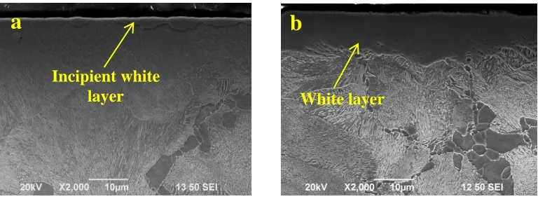
Pulsed plasma nitriding of VMS promotes morphological changes in the surface micro-roughness of the samples, for all processing conditions. The SEM micrographs of the figure 1 shows surface views of samples nitrided using current densities of a) 0.5 mA/cm2 and b) 1.5 mA/cm2. It can be appreciated an increase in the surface roughness level when the applied current density increase from 0.5 mA/cm2 to 1.5 mA/cm2, these fact occurs for all samples processed using current density above 0.5 mA/cm2. Increasing in roughness can be related to the formation of semi spherical particles on the surface of samples, which could be product of a highest interaction between samples surface and nitrogen from plasma. Figure 2 shows a cross view of plasma nitrided samples using current densities of a) 0.5 mA/cm2 and b) 1.5 mA/cm2. It can be appreciated an incipient white layer (Maximum thickness of 3 m) for sample treated at 0.5 mA/cm2
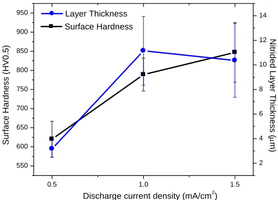
, which increase in thickness when the current density is modified to higher values. As it can be noted in the graph of figure 3, the thickness of the white layer increase from 3 m for treatment at 0.5 mA/cm2 to around 11 m for samples nitrided at 1.0 mA/cm2. Non additional significance variation in white layer thickness is registered when 1.5 mA/cm2 is used as nitriding current density.
Figure 1. SEM surface views of samples processed using current densities of a) 0.5 mA/cm2 and b) 1.5 mA/cm2.
Figure 2. SEM cross view of samples nitrided using current densities of a) 0.5 mA/cm2 and b) 1.5 mA/cm2
White layer Incipient white
layer
a
b
[image:4.596.103.500.363.506.2] [image:4.596.108.492.574.716.2]
It is well established that the discharge current density in a plasma assisted process is directly related with the parameter identified as ion fluence (F) [10, 11, 12]. F is defined as the quantity of ions from plasma impinging on the processing samples surface and it is additionally related with parameters as duty cycle and frequency for case of pulsed discharges [12]. In this sense, for a constant duty and frequency, the quantity of nitrogen ions impinging on surface of samples during pulsed plasma nitriding process will increase when the discharge current density grows. So, there will be greater nitrogen availability on the surface of samples and, if temperature is adequate, there will be a higher interaction level between atoms from substrate and nitrogen from plasma, resulting in formation of consistent and thicker compounds layers. The increase in ion fluence brings together an increase in the sputtering phenomenon [11] which in this case, could limit the growing of white layer when 1.5 mA/cm2 is used as nitriding current density. It has been reported, the negative influence of sputtering on growing of nitrided layers [13].
Graph of figure 3 also shows the relationship of surface hardness with the current density used during nitriding process. As a firs highlight, it is noted that plasma nitriding treatment let to increase the surface hardness of VMS from 312 HV0.5 to values around 847 HV0.5 (1.5 mA/cm2), which can be translated as an increase in the surface hardness around 2.7 times. A detachable finding is the fact that although no presence of consistent white layer on sample nitrided at 0.5 mA/cm2, surface hardness close to 620 HV0.5 were obtained, which can be related to obtaining of a hard consistent diffusion zone. It is important to remark that although no significant change in the white layer thickness is registered when current density change from 1.0 mA/cm2 to 1.5 mA/cm2, there was an increased in surface hardness from 789 HV0.5 to 847 HV0.5 respectively.
0.5 1.0 1.5
550 600 650 700 750 800 850 900 950 Surface Hardness
Discharge current density (mA/cm2)
[image:5.596.162.435.455.652.2]Su rfa ce H a rd n e ss ( H V0 .5 ) 2 4 6 8 10 12 14 Layer Thickness N itr id e d L a y e r T h ick n e ss ( m)
Figure 3. Surface harness and nitrided layer thickness as a function of discharge current density.
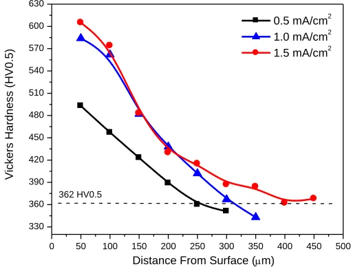
particular for each sample. In these sense the determinate treatment depth was around 250 m, 311 m and 400m form samples processed using 0.5 mA/cm2
, 1.0 mA/cm2 and 1.5 mA/cm2 respectively.
0 50 100 150 200 250 300 350 400 450 500
330 360 390 420 450 480 510 540 570 600 630
362 HV0.5
Vickers Ha
rd
ne
ss (HV0.5
)
Distance From Surface (m)
0.5 mA/cm2 1.0 mA/cm2 1.5 mA/cm2
Figure 4. Hardness profile of nitrided samples.
The XRD patterns obtained from nitrided samples are showed in figure 5. It can be appreciated the characteristic XRD reflections for iron in sample treated at 0.5 mA/cm2. Additionally, for this sample it is identified incipient reflections corresponding to Fe4N phase. These results are in coherence
with the SEM analysis which showed the presence of a thin white layer for this sample. For the case of samples nitrided at 1.0 mA/cm2 and 1.5 mA/cm2 there is a clear coexistence of both Fe4N and Fe3N. In
order to do evident predominance of one of both crystalline phases, it was computed the intensity quotient Iq (Fe4N/Fe3N) for reflections at 2 angles of 47.84° and 43.92°. These are the exclusively
highest intensity reflections which correspond to crystalline planes (200) and (2-11) of phases Fe4N
and Fe3N respectively. Iq for sample treated using 1.0 mA/cm2 results as 1.048 while, for sample
treated at 1.5 mA/cm2 the Iq obtained value was 0.98. In these sense, these data can be indicative of a lightly increase in the content of Fe3N when current density grows from 1.0 mA/cm2 to 1.5 mA/cm2,
which could be related with a higher incorporation of nitrogen as a consequence of the increasing in ion fluence. In the same way it can be noted the increase of around 7% in the intensity of XRD reflection at 38.48° (exclusively for Fe3N) when current density increase from 1 to 1.5 mA/cm2.
Based on results, it can be argued that although increase in the current density from 1 to 1.5 mA/cm2 do not modified significance the white layer thickness, the increase in nitrogen availability on the surface of samples induce a deeper penetration of nitrogen (thicker diffusion zone) and the lightly microstructural evolution from Fe4N to Fe3N in the compounds zone. In agreement to some works
carried out, here evidenced nitrides (Fe4N and Fe3N) in a white layer promotes the registered
increasing in surface hardness, as well as the increase in the tribological properties as wear and abrasion as well as fatigue resistance [14,15].
[image:6.596.171.426.135.329.2]
35 40 45 50 55 60 65 70 75 80
Fe 4 N Fe 4 N Fe 4 N
1.5 mA/cm2
1.0 mA/cm2
0.5 mA/cm2
Fe Fe Fe 3 N Fe 3
N / Fe
4 N Fe 3 N Fe 4 N Fe 3 N Fe 3
N / Fe
4 N Fe 3 N No rm al ize d in ten sity (AU)
2 Theta angle (Degrees)
Figure 5. XRD patterns of nitrided samples using different discharge current density values.
-810 -780 -750 -720 -690 -660 -630 -600 -570
1E-8 1E-7 1E-6 1E-5 1E-4 1E-3 0.01 0.1 1
Corrosion Current Density (mA/cm2)
Poten
tial
(m
V)
[image:7.596.175.427.75.293.2]Untretaed 0.5 mA/cm2 1.0 mA/cm2 1.5 mA/cm2
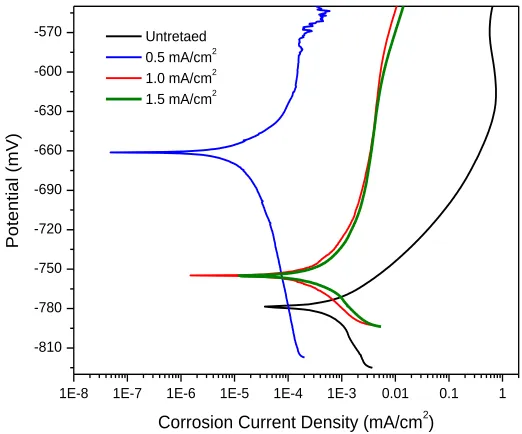
Figure 6. Potentiodynamic polarization curves of untreated and nitrided samples.
[image:7.596.166.427.342.559.2]
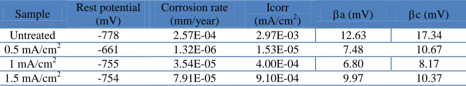
Table 1. Summary of electrochemical corrosion data obtained for untreated and nitrided samples.
Sample Rest potential (mV)
Corrosion rate (mm/year)
Icorr
(mA/cm2) a (mV) c (mV)
Untreated -778 2.57E-04 2.97E-03 12.63 17.34
0.5 mA/cm2 -661 1.32E-06 1.53E-05 7.48 10.67
1 mA/cm2 -755 3.54E-05 4.00E-04 6.80 8.17
1.5 mA/cm2 -754 7.91E-05 9.10E-04 9.97 10.37
Tafel extrapolation technique was used to determinate corrosion current (Icorr), corrosion rate, rest potential as well as Tafel anodic (a) and cathodic (c) slopes reported in the summary of table 1. For all the evaluated cases, it is evident the decreasing in the corrosion rate and Icorr values in reference to untreated sample. Untreated sample shows corrosion rate value of 2.57X10⁻⁴ mm/year while samples with a thicker white layer (1.0 and 1.5 mA/cm2) showed corrosion rate values of an order of magnitude below untreated sample. For these both cases, the decreasing in corrosion rate can be attributed to the development of a dense compound zone with around 10 m in thickness constituted by coexistence of both Fe3N and Fe4N [16]. This compounds layer aids to the passivation
phenomenon and prevents penetration of Cl- ions [17]. It is well established the preference of a smaller Tafel slope because it can be translated in a less polarization loss [18] in this sense, results show that for all nitrided samples, values of both Tafel anodic and cathodic slopes are below than such slopes determinate for untreated sample..
The augment in the discharge current density from 1.0 to 1.5 mA/cm2 kept the values of corrosion rate, rest potential and corrosion current in the same order of magnitude, which could be related with its similarity in the surface morphology and crystalline phase’s composition. It has been reported than predominance of Fe3N in the compounds zone brings together the increase in the
corrosion performance [19] which is attributed to its crystalline structure and higher nitrogen content; however for this case, the slightly increasing in the Fe3N content, although lightly modified the
surface hardness, is not enough to influence the corrosion performance.
For the specific case of sample treated at 0.5 mA/cm2 it was registered the highest corrosion performance of nitride samples obtaining the most noble potential and corrosion rate and current of two orders of magnitude in reference of untreated material. Although this sample has the lowest surface hardness values and the thinnest white layer, its white layer is constituted only by an individual phase (Fe4N) and it was visually appreciated as the sample with the lower roughness. In this sense it
could be inferred that such characteristics promote the best corrosion performance of set of evaluated samples.
4. CONCLUSIONS
Plasma nitriding at 0.5 mA/cm2 promotes formation of a 3 m average in thickness mono phase white layer constituted by Fe4N. The increase in discharge current density from 0.5 to 1.0 mA/cm2
encourages the growing of white layer to thickness around 10m which kept when the current density is additional increased to 1.5 mA/cm2. For both current densities, white layer are constituted by a coexistence of both Fe3N and Fe4N.
Surface hardness and case depth are influenced directly by the increase in the nitriding current density, getting the highest values (834 HV0.5 and 400 m case depth) in sample processed at 1.5 mA/cm2.
The electrochemical corrosion study reveals that for all analyzed cases pulsed plasma nitriding treatment significance improves the corrosion performance. Sample processed using 0.5 mA/cm2 as a nitriding current density promotes the decrease in the corrosion rate in two orders of magnitude in reference to untreated material and the shift to rest potential from -768 to -661 mV. Additionally it was evidenced a wide passive region generated in samples processed at 1.0 and 1.5 mA/cm2.
ACKNOWLEDGEMENTS
Authors acknowledge to the financial support from the Program for Innovation Stimulus, National Council for Science and Technology (CONACyT-México) and to “Manufacturera de Cigueñales de México S.A. de C.V.” (MACIMEX) for the support to conduct this study, providing the samples material and the scientific contribution of its research center I2DEAS.
References
1. T.N. Baker. Mat. Sci. Technol. 25 (2009) 1083.
2. David Pye. Practical nitriding and ferritic nitrocarburizing. ASM International, USA. 2003 3. Y.Z. Shen. K.H. Oh, D.N. Lee. Mat. Sci. Eng. A434 (2006) 314.
4. K. Y. Xie, C. Zhu, J.M. Cariney, S.P. Ringer, C.R. Killmore, F.J. Barbaro, J.G. Williams. Mat. Sci. Forum 654 (2010) 106.
5. F. Mahboubi, M.Samandi, D. Dunne, A. Bloyce, T.Bell. Surf. Coat. Technol 71 (1995) 135. 6. F. Mahboubi, M. Samandi, D. Dunne. Surf. Coat. Technol 85 (1996) 44.
7. E. E. Granda Gutiérrez, R. López Callejas, R. Peña Eguiluz, R. Valencia, A. Mercado Cabrera, S. R. Barocio, A. de la Piedad Benitez, J. S. Benítez Read and J. O. Pacheco Sotelo: J. Phys: Conf. Ser, 100 (2008) 062019.
8. Japanese Standard Association. Standard JSA-JIS G 0562 “Method of Measuring Nitrided Case Depth for Iron and Steel”. JSA Japan 1993
9. ASTM International Standards. ASTM G5. “Standard Reference Test Method for Making
Potentiostatic and Potentiodynamic Anodic Polarization Measurements” ASTM International USA 2004.
10.S. Mändl, J. Lutz, C. Díaz, J.W. Gerlach, J.A. García. I. Surf. Coat. Technol. 239 (2014) 116. 11.Naresh T. Deoli, Lucas C. Phinney, Duncan L. Weathers. Nuclear Instrum. Methods in Physics
Research B 332 (2014) 286.
12.R. López Callejas, R. Valencia Alvarado, A.E. Muñoz Castro, O.G. Godoy Cabrera, J.L. Tapia Fabela. Rev. Scientific Instrum. 73 (2002) 4277.
15.S.M. Hassani-Gangaraj, A. Moridi, M. Guagliano, A. Ghidini, M. Boniardi. Int. J. Fatigue. 62 (2014) 67.
16.A. Basu, J. Dutta Majumdar, J. Alphonsa, S. Mukherjee, I. Manna. Mater. Letters 62 (2008) 3117. 17.Yang Li, Liang Wang, Lie Shen, Dandan Zhang, Chunhua Wang. Surf. Coat. Technol. 204 (2010)
2337.
18.Robert Steinberger-Wilckens, Werner Lehnert,. Innovations in Fuel Cell Technologies. Royal Society of Chemistry. Germany 2010. .
19. S.D. Oliveira, A.P. Tschiptschin, C.E. Pinedo, Mater Des. 28 (2007)1714