1 Highlights
Development and progress in Zn-Ce flow batteries are comprehensively reviewed.
Electrode thermodynamics, electrode kinetics and cell performance aspects are included.
The kinetics of Ce redox reactions in sulphuric and methanesulfonic acids are summarised.
The critical aspects of zinc deposition and stripping in methanesufonic acid are considered.
The performance of laboratory half-cells and flow cells is illustrated.
3
Revised version of Invited review paper for ChemPlusChem: Special Issue – Metal-Air and Redox Flow Batteries, 2014. Guest Editors: Jaephil Cho, Linda F. Nazar & Peter G. Bruce
18 August 2014
The development of Zn-Ce hybrid redox flow batteries for energy storage and
their continuing challenges
Frank C. Walsh. a,b Carlos Ponce de Léon, a Len Berlouis, b George Nikiforidis, c Luis F. Arenas-Martínez, a David Hodgson,d David Hall. e
a.Electrochemical Engineering Laboratory, Engineering Sciences, University of Southampton, Highfield, Southampton, SO17 1BJ, UK
b. WestCHEM, Department of Pure and Applied Chemistry, University of Strathclyde, Glasgow G1 1XL, UK
c. School of Energy and Environment, City University of Hong Kong, Kowloon, Hong Kong.
d. Electrochemical Innovation Lab, Department of Chemical Engineering, University College London, Torrington Place, London WC1E 7JE, UK
e. C-Tech Innovation, Capenhurst, Chester, CH1 6EH, UK * Author for correspondence; f.c.walsh@soton.ac.uk
Abstract
The Zn-Ce flow battery is a recently introduced hybrid redox flow battery (RFB) but has been extensively studied in the laboratory and at the industrial pilot-scale since its introduction in 2005. The cell has the highest open-circuit cell potentials amongst aqueous RFBs, which can exceed 2.4 V at full charge. While original patents were filed in 2004 and 2005, the history of the half-cell reactions stretches back many decades, the Ce(IV)/Ce(III) redox couple being well studied in sulphuric acid as a redox mediator in organic electrosynthesis or in nitric acid for specialist cleaning in the chemical and nuclear industries while zinc deposition and stripping in acid media are well known in hydrometallurgy and electroplating of metals as well as in other batteries using zinc negative electrodes. Methanesulfonic acid electrolytes were introduced in surface finishing several decades ago but their use in flow batteries is only 20 years old. This review considers the thermodynamics and kinetics of the electrode reactions (desired and secondary) in each half-cell, operational variables, materials for cell components, cell design and performance of the zinc-cerium flow battery. Continuing challenges are highlighted and critical research needs for the science and technological development are considered.
4 Contents
1. Introduction
2. The cerium (positive) electrode 2.1 General
2.2 Electrolytes
2.3 Electrochemical measurements 2.3.1 Linear sweep voltammetry
2.3.2 Concentration of methanesulfonic acid
2.3.3 Concentration of cerium (III) methanesulfonate 2.3.4 Electrolyte temperature
2.3.5 Reversibility of the Ce(III)/Ce(IV) redox couple 3. The zinc (negative) electrode
3.1 General
3.2 Common electrode materials 3.3 Porous, 3-D substrates 4. Cell design and performance
4.1 The essential needs of a Zn-Ce cell 4.2 Electrolytes
4.3Electrodes
4.4Operational variables 4.4.1 Temperature
4.4.2 Electrolyte flow rate 4.4.3 Current density
4.4.4 Charge conditions and cycle life 5. Scale-up and progression
6. Conclusions and future developments
A review (ca. 12,000 words; 18 figures; 7 tables; 108 references) Impedance analysis at halfwave potential
(0.75 V) on Pt based electrode (5 g m-2 Etched) at
5
1.
Introduction
Redox flow batteries (RFBs) are one of the most viable technologies for larger scale energy
storage and load levelling in grid supply systems and have been the subject of several recent
reviews [1-4]. Classical RFBs utilise a solution based redox couple recycled through each
half-cell to a reservoir, a common strategy being to separate the half-half-cells by an ion exchange
membrane in a bipolar plate filter-press reactor.
Hybrid RFBs, which combine a solution-based redox couple with an electrode surface/solution
electrode reaction (such as solid state transformation, gas evolution/reduction or metal
deposition/stripping), include soluble lead, [5] zinc-air, [6] zinc-lead dioxide, [7] zinc-cerium [8]
and zinc-bromine [9]. Zinc-air, zinc-bromine and zinc-cerium flow cells have been considered
and contrasted in a recent book chapter and the significance of the negative standard potential of
the zinc electrode potential has been highlighted [10].
The principle of the Zn-Ce cell is shown in Figure 1. The desired electrochemical reactions are:
At the negative electrode
Zn Eo= 0.76 V vs. SHE (1) Zn(II) + 2e–
At the positive electrode
Ce(III) – e– Ce(IV) Eo= ca. 1.44 V vs. SHE (2)
The overall cell reaction is then
discharge charge
6
2Ce(III) + Zn(II) 2Ce(IV) + 2Ce(IV) + Zn Ecello= 2.2 V (3)
The cell reaction corresponds to a thermodynamic energy change, Gcell = 425 kJ mol–1 Zn. In
practice, hydrogen at the negative electrode and oxygen evolution at the positive one can occur
as side reactions during charge:
2H+ + 2e– = H2 Eo= 0.0 V vs. SHE (4)
2H2O 4e– = 1/2O2 + 4H+ Eo= 1.229 V vs. SHE (5)
This water electrolysis results in loss of charge efficiency as well as pH changes near the
electrodes and ohmic or safety problems linked with gas evolution. Another loss reaction is the
corrosion of the freshly deposited zinc when it is not under sufficient cathodic protection, i.e.,
the electrode potential is not sufficiently negative (see section 3) and leads to the dissolution of
the electrodeposited zinc:
Zn + 2H+ = Zn2+ + H2 (6)
Some of the main features during the development of the Zn-Ce RFB are indicated in Figure 2.
Early work on the Zn-Ce battery was carried out at EDA (which became AIC in 2007), from
1999 in California, USA, and a patent was granted in 2004 [8]. Between 1999 and 2009,
EDA/AIC claim to have raised approximately $40 million to support this R&D effort. In 2005,
the newly formed company Plurion was opened in Glenrothes in Scotland. In 2009, Scottish
7
economic downturn being severe for an emerging high technology company with a single
product in its early development phase.
The concept of the zinc-cerium battery originally resulted from the high positive standard
potential of the Ce(IV)/Ce(III) couple, a high negative potential for Zn dissolution/deposition,
the high solubility of metal ions in aqueous methanesulfonic acid [1] and the possibility of
generating the highly oxidising, cerium(IV) with good current efficiency at an inert anode
[11,12]. In addition, the Ce(IV)/Ce(III)couple has been reported to have relatively fast kinetics
in a variety of media [13-19]. The idea to employ methanesulfonic acid as the electrolyte for the
zinc/cerium battery was disclosed in US Patents [20, 21] although much of the practical
development was carried out later at Plurion [22].
Figure 1 shows this chemistry in a unit cell with a cation exchange membrane and electrolytes
containing only zinc(II) and cerium(III). In practice, the battery commonly consists of multiple
unit cells compressed together in a bipolar stack with massive end-plates. The size of the
electrodes and number of cells determine the maximum battery current and cell potential,
respectively. In practice, the membrane is not completely selective to proton transport and over
time, mixing of the zinc(II) and cerium(III) ions occurs. This has resulted in operating the
battery without a membrane or with both half-cell electrolytes containing both zinc(II) and
cerium(III) ions. The performance of each half-cell reaction will be outlined while cell
components and cell design will be discussed. In particular, this review considers the importance
of operational conditions and cell components on the performance of both divided and undivided
8
The Zn(II)/Zn couple is attractive as the negative electrode in aqueous redox flow batteries since
(a) Zn(II) is highly soluble in many aqueous electrolytes, b) the couple has a more negative
standard potential (–0.76 V vs. SHE) than almost any other possible couple in aqueous media
and c) the reaction has rapid kinetics allowing both charging and discharging with small
overpotentials. At this potential, the hydrogen evolution reaction (HER) via proton reduction is
thermodynamically the preferred reaction but zinc is a relatively poor electrocatalyst for HER.
Hence, charging and discharging a zinc electrode is possible under controlled conditions but
performance is always limited by the current efficiency for zinc deposition during charge and the
stability of the zinc to corrosion on open-circuit (i.e., during storage in the charged state). The
other challenge is to deposit the zinc metal as a compact, uniform layer free of dendrites or
voids. With large area electrodes, ‘shape change’ is a related problem depicted by more
pronounced deposition occurring in the lower regions of the cell during charge cycling.
Zinc electrodes have a well-established position in battery technology [1, 10, 23]. Zinc/carbon
primary batteries (Leclanché cells) were amongst the earliest batteries while zinc/air and
nickel/zinc batteries have also found markets. Amongst all redox flow batteries, the most
successful is the zinc/bromine flow battery [24]. The zinc/cerium flow battery continues to
attract substantial interest for energy storage, however, primarily due to its relatively large
open-circuit cell potential on full charge (Ecell = ca 2.5 V). The unit Zn-Ce cell is usually operated
with acid half-cell electrolytes (usually methanesulfonic acid) with a proton exchange membrane
separating the electrodes.
Much of the available information on Zn-Ce flow batteries is due to research at the universities
of Southampton and Strathclyde in the PhD programmes of P.K. Leung (2007-2010) [25] and G.
9
RFB are discussed in terms of the operating conditions of the cell. Charge current densities of 5
mA cm2 to 40 mA cm2 have been employed over the 25-60 oC temperature range. Several carbon composite materials and porous, 3-D carbon electrodes have been evaluated for use as
the negative electrode whilst for the positive electrode, a platinised titanium mesh has typically
been employed The half-cells were separated by a Nafion® 117 proton exchange membrane.
2.
The cerium (positive) electrode
2.1 General
The Ce(IV)/Ce(III) redox couple has been well studied in sulphuric acid as a redox mediator in
organic electrosynthesis [7] or in nitric acid for chemical decontamination and specialist
cleaning in the chemical and nuclear industries [27]. TheCe(IV)/Ce(III) redox process, reaction
(2), suffers competition from oxygen evolution, reaction (5) during battery charging, which
results in a lowering of voltage and charge efficiencies and the need to control current density or
potential.
The voltammetry of the Ce(IV)/Ce(III) couple has been studied in a variety of acidic, aqueous
solutions and the couple has been found to have quite rapid kinetics [14]. In most media,
however, the solubility of the cerium species is insufficient for practical flow battery operation.
Interest in Ce(IV) in methanesulfonic acid electrolytes as an oxidising agent in the mediated
electrochemical oxidation of organic compounds has generated useful background information
for the application of the Ce(IV)/Ce(III)couple in batteries. Preliminary voltammetric studies
[28, 29] showed that the Ce(IV)/Ce(III) is a quasi-reversible couple in methanesulfonic acid.
Spotnitz et al [30] have reported the solubility of the cerium species as a function of
methanesulfonic acid concentration, showing that it declined rapidly above 4 mol dm–3 acid. They also reported on its electrolysis in three different parallel plate reactors including a cell Impedance analysis at halfwave potential
(0.75 V) on Pt based electrode (5 g m-2 Etched) at
10
with a reticulated Ti electrode coated with a precious metal oxide catalyst. The performance of
the cells declined with anodes in the order PbO2 > Pt > coated Ti > C. For the Pt electrode, the
current efficiency was 96 % at a current density of 100 mA cm–2. Harrison and Theoret [31] extended this development to larger flow cells and investigated the influence of current density,
flow rate and anode material. Carbon was not considered a suitable material and the authors
employed a DSA-coated titanium. The technology was scaled up for a 100 tonne/year
anthraquinone plant where the electrolytic step was the cerium mediated oxidation of
naphthalene to naphthaquinone.
Xie et al [32] used cyclic voltammetry to find the appropriate conditions for the use of the
Ce(II)/Ce(III) couple in a flow battery. They reported that the Ce(IV)/Ce(III) couple has a more
positive standard potential in methanesulfonic acid than in sulphuric acid, consistent with the
single charge anion being a weaker complexing agent for Ce(IV). The couple has the advantage
that both Ce(IV) and Ce(III) are completely stable up to 60°C although at more elevated
temperatures, Ce(IV) may slowly precipitate from electrolytes containing concentrated Ce(IV).
The Ce(IV)/Ce(III) couple has rather rapid kinetics at a graphite electrode leading to a cyclic
voltammograms with a peak separation close to that expected for a reversible couple. On the
other hand, the standard rate constant measured at Pt is significantly lower. At sufficient
overpotentials, both the oxidation and reduction reactions may be driven into mass transport
control. A parallel plate membrane cell with 3 × 3 cm electrodes was examined as a battery
using constant current cycling. The positive electrode here was a 3 mm thick carbon felt with a
11
Leung et al [33] also used voltammetry to examine the kinetics of the couple at Pt and glassy
carbon electrodes. Ce(IV) reduction was particularly poor at glassy carbon. Even at Pt, the peak
separations were substantial due to the large IR drop due to the high Ce(III) concentrations used
here in order to mimic the battery situation. As expected, the kinetics became faster at higher
temperatures. The optimum concentration of methanesulfonic acid in the electrolyte is a
compromise of several factors. A high acid concentration is advantageous to maintain Ce(IV) in
solution but this also decreases the solubility of Ce(III). In addition, increasing the concentration
of methanesulfonic acid decreased the amount of competing O2 evolution reaction (OER) during
charge but also increased the viscosity of the electrolyte which reduced the mass transfer
coefficient. Using a membrane divided cell and a three-dimensional electrode [34], containing
either Pt/Ti meshes, graphite felt or carbon felt (to aid the slow kinetics of the Ce(IV)/Ce(III)
couple), it was possible to obtain an 80 % conversion of 0.8 mol dm–3 Ce(III) to Ce(IV) using a current density of 50 mA cm-2 for 4 hours, representing a charge efficiency >75 %.
The use of the Ce(III)/Ce(IV) redox couple has long been suggested as the positive electrode
reaction for use in flow batteries [35-37]. This idea was exploited in the zinc-cerium [38-40]
and vanadium-cerium redox flow batteries [41] as the couple offers a large positive potential,
between 1.28 V and 1.72 V vs. SHE depending on the supporting electrolyte [42], and so leads
to a high cell voltage for a charged battery.
Cerium in methanesulfonic acid is an attractive half-cell electrolyte for flow battery application
as it can be easily prepared at concentrations as high as 1 mol dm–3 compared to less than 0.5 mol dm–3 in sulphuric acid. In order to optimise the resulting cerium half-cell as the positive electrode reaction in a redox flow battery, an improved understanding of the electrochemical
12
crucial. To date, only a limited number of studies have been directed to the electrochemistry of
cerium in methanesulfonic acid, the reduction of Ce(IV) and to the reversibility of the
Ce(III)/Ce(IV) system. Earlier studies have mainly focused on the oxidation of Ce(III) in
sulphuric and nitric acid electrolytes. Previous studies of the oxidation of Ce(III) and reduction
of Ce(IV) in methanesulfonic acid have typically used 0.01 to 0.1 mol dm–3 cerium (III) methanesulfonate [43-45]. Such a low concentration of the electroactive species is not practical
in a redox flow battery since the amount of energy that can be made available in the system
depends on the concentration of the electroactive species. These investigations are useful to
calculate the kinetic parameters of the Ce(III)/Ce(IV) redox couple but a cerium based flow
battery requires a higher concentration of cerium (III) methanesulfonate, typically 0.5 to 2.0 mol
dm–3 in a wide range of methanesulfonic acid concentration e.g. from 1.0 to 6.0 mol dm–3. This is mainly due to changes in the electrolyte concentration during the charge-discharge cycles.
During battery charge, for every Ce(III) oxidised, a proton is transferred to the negative
electrolyte from the positive side and the generated Ce(IV) species is complexed by the
methanesulfonate anions.
Leung et al have reported the electrochemistry of the Ce(III)/Ce(IV) redox couple in
methanesulfonic acid over a range of electrolyte compositions typically found in a redox flow
battery [33]. The oxidation of Ce(III) and reduction of Ce(IV) were studied via cyclic
voltammetry at a platinum disc electrode and during constant current electrolysis in a divided,
two compartment parallel plate flow reactor. The reversibility of the Ce(III)/Ce(IV) redox couple
as a function of Ce(III) and methanesulfonic acid concentrations at various electrolyte
temperatures was also investigated. The OER was inhibited at high acid concentrations (5 mol
13 2.2 Electrolytes
Figure 3 shows the cyclic voltammetry of the Ce(III)/Ce(IV) redox couple recorded at platinum
and glassy carbon disk electrodes in an electrolyte containing 0.8 mol dm–3 cerium(III) methanesulfonate and 4.0 mol dm–3 methanesulfonic acid at 22 oC using a potential sweep rate of 50 mV s–1. The oxidation of Ce(III) started at approximately + 1.2 V vs. Ag|AgCl on both electrodes and the anodic current rose steadily as the potential became more positive. A higher
current density of 39 mA cm–2 was recorded on the platinum electrode compared with c.a. 25 mA cm–2 on the glassy carbon electrode at around 1.65 V vs. Ag|AgCl for both electrodes. At a more positive potential, the anodic current at the glassy carbon electrode decayed while at the
platinum electrode continued to rise sharply due to the oxygen evolution reaction (and the
formation of platinum oxides) [46,47]. The influence of oxygen evolution reaction does not
seem to be significant on the glassy carbon electrode as the current during the oxidation of
Ce(III) on this electrode did not increase at more positive potentials. However, this can also be
attributed to the oxidation of carbon at such potential. On the reverse scan, a more negative
potential was required for the reduction of Ce(IV) on the glassy carbon than on the platinum
electrode. A maximum cathodic peak current density of 15 mA cm–2 on platinum was observed at c.a. + 1.05 V vs. Ag|AgCl while only 7.5 mA cm–2 at + 0.65 V vs. Ag|AgCl at the glassy carbon electrode. The separation between the oxidation and reduction peaks on each electrode
was approximately 0.7 V on platinum and 1.0 V on carbon. The anodic current was higher than
the cathodic one and the ratio of cathodic to anodic peak current was approximately 0.4 to 0.6 on
both electrodes. Platinum gives a more favourable electrochemical response than carbon for the
oxidation of Ce(III) and reduction of Ce(IV) in methanesulfonic acid because the peak
separation is smaller. Several features in the voltammogram are worth mentioning: the
14
cathodic to anodic peak current is far below 1, the value expected for an ideally reversible
system. The magnitude of oxygen evolution as a secondary reaction on the platinum electrode
also needs to be reduced in order to improve the current and conversion efficiencies. Since
platinum gave a higher oxidation current than glassy carbon and the separation between the
oxidation and reduction peaks was smaller than using the glassy carbon electrode in the cyclic
voltammograms, subsequent studies were carried out on a platinum electrode.
2.3 Electrochemical measurements
2.3.1 Linear sweep voltammetry
Figure 4a) shows the effect of the potential sweep rate on the cyclic voltammetry of the
Ce(III)/Ce(IV) redox couple on a platinum electrode in an electrolyte containing 0.8 mol dm–3 cerium (III) methanesulfonate and 4.0 mol dm–3 methanesulfonic acid at 22 oC. The peak current density of the oxidation and reduction processes increased linearly with the square root of the
potential sweep rate. Figure 4b) shows the linear Randles-Sevćik relationship [48-50] indicating
that the oxidation of Ce(III) and reduction of Ce(IV) in methanesulfonic acid were diffusion
limited. In this work, the diffusion coefficient (D) of cerium(III) ion was determined using the
anodic current densities as the experiment was carried out in the cerium(III) electrolyte. Using
the value of the slope from this plot during the oxidation process, the diffusion coefficient of
Ce(III) ion in methanesulfonic acid was estimated to be 1.67 10-6 cm2 s–1 at 22 oC. This value agrees with previous measurements of diffusion coefficients that where in the range of 0.27 to
15
The D value of Ce(III) ions in methanesulfonic acid was slightly smaller than those reported for
many metal ions in aqueous electrolytes, which are typically (4.0 to 6.0) 10–6 cm2 s–1 [52,53] possibly due to the complexation with the methanesulfonate anions [45]. Indeed, lower diffusion
coefficient values were found at increased methanesulfonic acid concentration, e.g. in an
electrolyte containing 0.152 mol dm–3 cerium (III) methanesulfonate, the diffusion coefficient of Ce(III) was approximately 0.69 10-6 cm2 s–1 in 1.0 mol dm–3 methanesulfonic acid but only 0.27 10–6 cm2 s–1 in 4.0 mol dm–3 methanesulfonic acid [51].
At all potential sweep rates, the ratio of cathodic to anodic peak current was approximately 0.5.
The charge density for the reduction of Ce(IV) was lower than that involved in the oxidation of
the Ce(III) ion possibly due to the OER secondary reaction. Earlier investigations also suggested
that the larger anodic peak current could also be due to the contribution of the weak adsorption
of Ce(III) ions on the electrode surface, which was demonstrated via cyclic voltammograms of
the Ce(III)/Ce(IV) redox couple in sulphuric and methanesulfonic acids [45]. Recent studies
have also shown that the cathodic and anodic peak currents can be brought closer via the
complexation of Ce(III) and Ce(IV) ions with ligands such as ethylenediaminetetraacetic acid
and diethylenetriaminepentaacetic acid [54,55]. Such a strategy has been advantageous since the
reversibility of the Ce(III)/Ce(IV) redox couple was significantly improved and higher charge
densities were obtained [56]. The work also showed that the faster electrochemical kinetics in
the presence of the ligands are due to a higher charge transfer coefficient and an increased
electron transfer rate constant for the Ce(III) Ce(IV) redox reaction. The electron transfer
rates were also found to be similar for the oxidation of Ce(III) and the reduction of Ce(IV),
confirming that an improvement in the reversibility of these reactions could be achieved using
16
By increasing the potential sweep rate during the oxidation of Ce(III), the peak potential shifted
to more positive values while for the reduction of Ce(IV) to more negative potentials. The
separation of the peak potentials increased at higher potential sweep rates e.g. 560 mV at 8 mV
s–1 compared to 790 mV at 64 mV s–1. Devadoss, Noel, Jayaraman and Basha [43] reported in an electrolyte containing 0.034 mol dm-3 cerium (III) methanesulfonate in 4.0 mol dm–3 methanesulfonic acid at a glassy carbon electrode that the reduction peak shifted by
approximately –100 mV as the potential sweep rate increased from 10 to 160 mV s–1. Earlier investigations also showed a quasi-reversible behaviour of the Ce(III)/Ce(IV) redox couple in
commodity electrolytes, such as sulphuric acid [35, 57]. These observations suggest poor
reversibility of the Ce(III) to Ce(IV) reaction.
2.3.2 Concentration of methanesulfonic acid
Cyclic voltammograms of the Ce(III)/Ce(IV) redox couple were recorded at a platinum electrode
in a wide range of methanesulfonic acid concentration from 0.1 to 5.0 mol dm–3. Figure 5a) shows that the anodic current density for the oxidation of Ce(III) decreases as the concentration
of methanesulfonic acid increased when the electrolyte contained 0.8 mol dm–3 Ce(III) methanesulfonate. For example, the anodic peak current density was approximately 50 mA cm–2 in 2.0 mol dm–3 methanesulfonic acid but no oxidation peak (but a plateau) was observed with 5.0 mol dm–3 acid concentration, although the current density reached 20 mA cm–2. The change in the peak current density was due to the increase in the solution viscosity at high acid
concentrations and to the high conductivity of the acid at low concentrations in aqueous
electrolytes [33]. Other findings reported in the literature also showed similar observations: the
17
current after the oxidation of Ce(III) was caused by oxygen evolution, which was found to be
influenced by the methanesulfonic acid concentration. The linear sweep voltammograms in the
absence of Ce(III) with different concentrations of the acid in Figure 5b) show that oxygen
evolution shifted to more positive potentials at a higher acid concentration. For example, at an
electrode potential of c.a. +1.8 V vs. Ag|AgCl, the anodic current density was c.a. 80 mA cm–2 in 2.0 mol dm–3 methanesulfonic acid, but at the same potential the current density was only 40 mA cm–2 in 5.0 mol dm–3 methanesulfonic acid. Although similar behaviour has been found in sulphuric acid [58], the cathodic current density was smaller. These findings suggest that the
oxidation of Ce(III) is the dominant reaction at higher concentrations of methanesulfonic acid
and is consistent with observations during the experiment where less oxygen bubbles appeared
on the electrode surface during the oxidation of Ce(III) under these conditions.
Figure 5c) shows the charge density involved in the oxidation and reduction of Ce(III) and
Ce(IV) ions respectively, vs. the concentration of methanesulfonic acid. The charge density
calculated from the area under the curve of the cyclic voltammogram, during the oxidation of
Ce(III) is constant up to 1 mol dm–3 of methanesulfonic acid and then decreases sharply as the acid concentration increases. This is consistent with the observations made on the cyclic
voltammograms shown in Figures 5a) and 5b). The charge density for the reduction of Ce(IV)
increased significantly with the concentration of acid up to 1 mol dm–3, after that the charge increase is slow and reaches a maximum at 4.0 mol dm–3 methanesulfonic acid. A further increase in the acid concentration led to a slight reduction in both charge and current density for
the reduction of Ce(IV). This is attributed to an increase in solution viscosity [59] and the
solubility limit of Ce(III) in 5.0 mol dm–3 in methanesulfonic acid, which might have been exceeded. At such a high acid concentration, the solubility limit of Ce(III) was estimated to be
18 2.3.3 Concentration of cerium (III) methanesulfonate
Figure 6 shows that the charge density for both the oxidation of Ce(III) and reduction of Ce(IV)
increased when the Ce(III) methanesulfonate changed from 0.1 to 1.0 mol dm–3 in a solution containing 4.0 mol dm–3 methanesulfonic acid. A further increase in the concentration of cerium (III) methanesulfonate to 1.2 mol dm–3, which was a relatively viscous solution, led to a reduction in the charge density for both processes. This was due to the limited solubility of
Ce(III) at such acid concentration as previous results showed that 1.0 mol dm–3 was the solubility limit for Ce(III) and Ce(IV) in 4.0 mol dm–3 methanesulfonic acid at room temperature [44, 60]. This observation is also consistent with previous results where a high concentration of Ce(III) could only be achieved in a low concentration of methanesulfonic acid. The
concentration of Ce(IV) however, could only be increased in higher methanesulfonic acid
concentrations [44].
Since the acidity of the electrolyte in the flow battery will change during charge-discharge
cycles, the challenge is to use an appropriate concentration of methanesulfonic acid which
provides sufficient solubility for both Ce(III) and Ce(IV) species. The above results indicate that
a solution with higher concentration of Ce(III), e.g. 1.5 to 2.0 mol dm–3 could be prepared in a low acid concentration. However, the Ce(IV) solution obtained during or from a constant current
electrolysis under these conditions was highly viscous with evidence of a slurry [60]. A high
concentration of Ce(IV) could be prepared if the concentration of the acid was high but the
solubility of Ce(III) became limited and the Ce(III)/Ce(IV) redox couple demonstrated poor
19 2.3.4 Electrolyte temperature
Figure 7 shows that the charge density during the oxidation of Ce(III) increases with
temperature. The reduction of Ce(IV) also increased but reached a maximum at 50 oC. The higher charge density for the oxidation of Ce(III) could be due to the simultaneous oxygen
evolution reaction which is favourable at high temperatures. Cyclic voltammograms recorded for
0.01 mol dm–3 Ce(III) in 1.0 mol dm–3 sulphuric acid also showed an increase in the charge density at elevated electrolyte temperature, e.g. 60 oC [35]. During the electrolysis of Ce(III) ions in both undivided
and divided electrochemical cells in 3.0 mol dm3 nitric acid electrolyte, the applied cell potential difference decreased slightly as the temperature increased due to improved reaction
kinetics, increased electrolyte conductivity and reduced viscosity. The study also showed that the
current efficiency of the electrolysis of Ce(III) to Ce(IV) improved from 77 % at 40 oC to 93 % at 90 oC in nitric acid [59].
An increase in the diffusion coefficient of Ce(III) ions and the rate constant for Ce(III) oxidation
have also been observed at elevated electrolyte temperature [42]. Literature studies confirmed
that an Arrhenius, semi-logarithmic plot of the diffusion coefficient against the inverse of the
electrolyte temperature is a linear relationship for the Ce(III) Ce(IV) redox reaction in nitric
and sulphuric acid electrolytes [58].
2.3.5 Reversibility of the Ce(III)/Ce(IV) redox couple
Cyclic voltammetry studies at a platinum electrode in various electrolyte compositions have
20
separation of the anodic and cathodic peak potentials and the ratio of cathodic to anodic peak
currents. Tables 1A and 1B summarise the results of cyclic voltammetry studies in sulphuric
acid and in other electrolytes for the proposed Zn-Ce RFBs. Table 2 shows data relating to the
reversibility of the Ce(IV)/Ce(III) system under different conditions. The peak separation of
potentials decreased at lower concentrations of cerium (III) and methanesulfonic acid as well as
at higher electrolyte temperatures. The ratio of cathodic to anodic peak current density varied
from 0.3 to 0.65 depending on the electrolyte composition. The ratio was closer to unity in an
electrolyte containing a higher concentration of methanesulfonic acid and cerium (III)
methanesulfonate as well as at an elevated electrolyte temperature (50 °C).
At higher concentrations of cerium (III) methanesulfonate and methanesulfonic acid, the
separation of oxidation and reduction peak potentials increased due to an increase in the ohmic
drop associated with larger current response and changes in the solution viscosity and
conductivity. The high concentration also reduced the reversibility of the Ce(III)/Ce(IV) redox
couple. At such concentration, the oxidation potential remained fairly constant but the reduction
potential became more negative leading to lower discharge cell potential difference of a
cerium-based redox flow battery. These observations agree with other studies, for example the
separation of peak potentials increased from 140 mV to 240 mV when the acid concentration
changed from 2 to 5 mol dm–3 in a solution containing 0.033 mol dm–3 of Ce(III) [45].
Although a low concentration of cerium (III) methanesulfonate leads to a narrower separation of
the peak potentials, such a low concentration of Ce(III) ions would not be practical for flow
battery applications. Besides, the use of a low concentration of methanesulfonic acid also limits
the solubility of Ce(IV) in the solution, hence the energy density available in a flow battery will
21
methanesulfonic acid has been suggested for flow battery applications. The use of elevated
electrolyte temperature could also provide a more reversible redox reaction but the temperature
range will be limited by the properties of the electrode materials as well as those of the
electrolytes. Table 2 summarises the impact of typical operational conditions used in RFBs on
the reversibility of the Ce(III)/(IV) redox couple.
3. The zinc (negative) electrode
3.1 General
As in all hybrid zinc redox flow battery systems [1-3], zinc is deposited on an inert collector
during charge. The zinc-halogen hybrids are amongst the most studied of the Zn-based redox
flow battery systems. Factors found to affect the zinc deposition include the electrode substrate,
the charging method, the cell geometry, the electrolyte hydrodynamics, the electrolyte
composition and the zinc electrode morphology. An investigation of zinc electrodeposition in
sulphuric acid has been carried out by Guillaume et al [61] who reported that the HER on
stainless steel was inhibited by the zinc deposits and that the deposit morphology was not
significantly influenced by current density. They also reported that increasing the concentration
of the zinc species (>2 mol dm–3) would yield higher deposition current efficiencies of 80%. However, some of the problems with the zinc-bromine battery does involve the HER at the
negative electrode on charge, which leads to lower charge efficiencies and also to non-uniform
deposition of zinc on random cycling [1]. Van Parys et al [13] investigated the zinc deposition
mechanism with simultaneous hydrogen evolution in an acidic sulphate solution (5 × 10⁻² mol dm3 ZnSO4 in 1 mol dm–3 Na2SO4). It was found that if gas bubbles were formed in the mass transport controlled region, the induced micro stirring increased the current density whereas if
the current was kinetically controlled, the current density decreased due to the increased
22
separator and redistribution of the zinc electrode active material on cycling as well as
de-zincification of the zinc electrode were found to be occur [13]. For this system, Ito et al[16]
reported that high electrolyte flow velocities, i.e. >15 cm s–1, improved the cycle life of the battery at 100 % depth of discharge.
In the industrial electrodeposition of metals, electrolyte additives are routinely used to control
the morphology and appearance of the deposits. Another objective of such additives is to reduce
simultaneous hydrogen evolved during the metal deposition process, viz. during the charging of
the battery. Classical glue and gum Arabic are the most commonly used additives in the
industry for the zinc electrowinning process [17, 18]. Glue has been reported to decrease the
grain size of the zinc deposit while gum Arabic changes the deposits orientation (basal to the
intermediate
plane). The search for better organic additives is still ongoing. It has been reported [18] that
TBABr (tetrabutyl ammonium bromide) can act as a dendritic growth suppressor whilst also
increasing the compactness of zinc deposits in alkaline zincate electrolytes. Increasing the
additive concentration though can also lead to the blockage of the active nucleation sites on the
cathode surface by adsorption of the additive, thereby decreasing the overall energy efficiency.
The use of gelatin (solid content: 80 mL g–1) to chlorine based electrolytes (pH = 4) has been shown to decrease the adsorption of H+ ions on active zinc sites and increasing the energy efficiency at 40 °C [20].
Two synthetic organic additives with superior performance to glue and gum Arabic have been
identified as nonylphenoloxylethylene [22] and 2-butyne-1, 4-diol [23]. The latter has been
reported to improve the zinc current efficiency in the presence of Ni impurities in an acidic
23
thiosemicarbazone (SaTSCN) have also been reported to achieve current efficiencies as high as
99 % and 97 %, respectively for zinc deposition in both alkaline and acidic solutions [62]. Ichino
et al[63] found that Pb(II) ions can be adsorbed at the electrode surface and strongly inhibit the
HER reaction during the zinc deposition process from acidic sulphate electrolytes. Both thiourea
and urea are known to improve the crystallographic orientation of the zinc deposits at pH = 0.5
[64]. In addition, it has been reported that decreasing the pH from 5.4 to 1 of a zinc electrolyte,
containing chromium in 0.6 mol dm3 ZnSO4.7H2O still allowed zinc deposition to occur well before the HER process [65]. The reduction in the pH resulted in a fall in the formation of
hydroxo-products of chromium in the electrolyte. Furthermore, compounds like indium have
been reported to increase the hydrogen overpotential [66]. The same effect has been reported for
polyethylene glycols (PEGs). [67]. It is important though that future studies should move in the environmental direction by investigating sustainable inhibitors and use of natural product
extracts.
3.2 Common electrode materials
Carbon-based composites are the most widely employed materials for the negative electrode in
the Zn-Ce hybrid RFB system [34, 68-71]. Much development has taken place over the last 20
years on these composite materials and various forms have been studied. Pure carbon and
graphite tend to be brittle and often difficult to work with. Hence, scaling-up to large dimensions
for use in stacks becomes a significant issue. As a result, composites of polymer binders and
conductive particles, such as carbon polymer composites [72, 73] and polymer-impregnated
graphite plates [34, 70, 74] are often used. These have the advantages of being low cost, light in
weight and having improved mechanical properties. A list of the carbon substrates is presented
24
expandable graphite have low through-plane electrical resistivity as well as low thermal
expansion but chemical stability in the methanesulfonic acid electrolyte used in the Zn-Ce
system is quite poor. On the other hand, the carbon composite materials, which are held together
by polymer binders, such as polyvinylidene difluoride, PVDF and high density polyethylene,
HDPE, [75] phenolic resin [75, 76] and polyvinyl ester (PVE) [77] have been found to be
chemically robust. These composites are commonly manufactured by compression/injection
moulding.
Cyclic voltammetry (Figure 8) has been carried out on these electrodes in neutral solutions of
sodium methanesulfonate containing 0.01 0.1 mol dm3 Zn2+ ions (Figure 8a) as well as in more concentrated zinc solutions (0.7 mol dm–3 to 2.0 mol dm–3) in methanesulfonic acid, (Figure 8b) [25,26,33,34,70]. A clear decrease in the potential for zinc nucleation with
temperature can be seen from Table 4, e.g. from –1.60 V vs. Hg|Hg2SO4|sat’d K2SO4 at 25 °C to
–1.54 V vs. Hg|Hg2SO4|sat’d K2SO4 at 60 °C for the carbon-PVDF composite electrode [70].
Rotating disk electrode (RDE) studies in this electrolyte allowed the diffusion coefficient of the
zinc(II) species to be obtained at different temperatures [25,26,33,34,70]. The value of D
increases with temperature from 4.8 × 10⁻⁶ cm2 s–1 at 25 oC to 8.5 × 10⁻⁶ cm s–1 at 40 oC and 12.7 × 10⁻⁶ cm2 s–1 at 60 oC, associated with a decrease in the viscosity of the electrolyte, from 0.0136 Pa s at 25 °C to 0.0056 Pa s at 60 °C. Further studies using the RDE system have been
carried out in order to obtain the standard heterogeneous electron transfer rate constant, k° for
the reaction at these composite electrodes [26, 70]. Data are taken from the mixed controlled
region of the RDE j-E curve using the Koutecky-Levich equation to determine the kinetic
parameters at potentials within this region (Figure 9). The k° value is then obtained from the plot
25
RT αnFE k
ln k
ln o
(8)
when E = E½, the half-wave potential chosen at the lowest rotation speed. The calculated rate
constant showed substantial variations for the various carbon-polymer composites substrates.
The HDPE-2 carbon composite exhibited slightly faster kinetics (k° = 1.57 103 cm s1 at 25 °C) compared to the other electrodes. For the C-PVDF, glassy carbon and HDPE-2 carbon
composite substrates, the rate constant increased from 1.16 103 cm s1 to 2.32 103 cm s1 when the temperature was increased from 40 °Cto 60 °C. The standard rate constant of the PVE electrode was smaller by a factor of 3.5 compared to the one of the HDPE-2 carbon, indicating
that kinetics on this electrode surface are slow, even at 60 °C. Interestingly, the values of
Mendoza et al[78] in chloride solution (0.5 mol dm–3 ZnCl2 and 0.4 mol dm–3 H3BO3) for the standard rate constant was8.73 × 10–3 cm s–1 for the glassy carbon electrode compared to 1.60 103 cm s1 in the methanesulfonate medium, emphasising the important role played by the CH3SO3counter ions in adsorption and complexation of the depositing species.
The nucleation and growth of zinc at the negative electrode on charge has been examined by
current density vs. time behaviour (Figure 10). The potential at which zinc deposition begins is
seen to decrease at higher temperatures but some variation occurs on the different
carbon-polymer composite surfaces, as indicated in Table 4. Nucleation studies on various carbon
electrode surfaces have been carried out in solutions containing different concentrations of
zinc(II) in 5.7 mol dm–3 MSA, using potential steps in the range from –1.60 V to –1.85 V vs.
26
and Hills [79] for instantaneous and progressive nucleation and growth of the nuclei. Normalised
plots for the nucleation of zinc at –1.68 V vs. Hg|Hg2SO4 on the PPG86 composite carbon
electrode presented in Figure 10a indicates that the nucleation here (and indeed on the other
composite materials) occurred via the instantaneous route [70]. The nucleation densities on
various carbon composite electrodes in 0.7 or 1.5 mol dm–3 Zn(II) + 5.7 mol dm–3 methanesulfonic acid are given in Table 5. The data from these tables clearly show No increasing
at more negative potentials and depending on the electroactive species concentration. The No
values found for the solution containing 0.01 mol dm–3 Zn(II) are in a similar range to the ones found by Marquez et al [80] for silver nucleation on glassy carbon electrodes from silver cyanide
solutions and by Yu et al [81] for zinc nucleation on glassy carbon from sulphate, chloride and
acetate solutions at 25 °C.
With an increase in temperature to 60 °C, the deposition potentials are considerably higher for
the PVE and PVDF electrodes, albeit at a lower zinc composition, Figure 10b) [26, 70]. For the
PVE carbon composite electrode, the difference was 310 mV while for the PVDF composite it
was ca. 140 mV. This unusual behaviour may be linked to the nature of the composite electrode
material. The higher temperature could lead to the expansion of the matrix which in turn would
reduce the electrode conductivity and so necessitating the need for the higher potential observed.
Yu et al., [81] showed that elevated temperatures resulted in increased No values in an alkaline
Zn/MnO2 battery but this study however used glassy carbon electrodes. Similar analyses have
been conducted for deposition from higher zinc concentrations (0.7 mol dm–3 and 1.5 mol dm–3) in 2.4 mol dm–3 MSA except that deviations in the experimental curves occur at longer times, possibly due to changing surface area of the deposit and some contribution from hydrogen
27
The behaviour of these electrodes under multiple galvanostatic charge-discharge cycles has also
been examined [26, 70]. The parameters varied here were the current densities employed, the
duration of the charge, the temperature and the flow velocity. Typical chronopotentiometry data
recorded during these experiments are shown in Figure 11 which shows a steady potential of ca.
–1.68 V vs. Hg|Hg2SO4 during zinc deposition and ca. –1.2 V vs. Hg|Hg2SO4 during dissolution
at a current density of 50 mA cm2 at 60 °C. The open-circuit potential of 1.41 V vs.
Hg|Hg2SO4 is consistent with zinc electrodeposition on the composite carbon surface and the
data indicates that the overpotentials for the deposition and dissolution processes are similar in
magnitude. The charge efficiencies (C) evaluated from these curves for several of the composite electrodes are shown in Figure 12. The results indicate that the C-PVDF and the
HDPE-1 composite materials gave the best performance of all the electrodes examined here with
C averaging 96 %. The PVE and HDPE-2 electrodes exhibited C values averaging 95 % and
93 %, respectively. The glassy carbon electrode data is included in the figure to illustrate the
superior behaviour of the carbon-polymer composites, especially the HDPE, PVDF and
C-PVE materials, in achieving high charge efficiency for the zinc half-cell reaction of the hybrid
Zn-Ce system.
The effect of charging time on the charge efficiency and on the stability of the zinc
electrodeposits was also examined in a study where the composite material was mounted onto a
rotating disk set up and this also allowed the impact of solution velocity to be evaluated [26,70].
As the data of Figure 13 indicates, an electrode rotation rate of 10 Hz (Re = 200) for the
C-PVDF electrode, stable deposits (capable of remaining on the material surface then undergoing
anodic dissolution) could be formed over the charging duration of 5 min or less. At that current
28
Zinc-based systems tend to suffer from a high rate of self-discharge because of the highly
reducing zinc species. The main problem here is the high corrosion rate of the zinc
electrodeposit in the acid electrolyte via hydrogen evolution. Thus, the discharge current density
is important in this Zn-Ce system, since the freshly electrodeposited zinc is sitting in an
electrolyte consisting of ca. 2 mol dm-3 H+. Indeed, as Figure 14 shows, discharge current densities below 50 mA cm-2 lead to a substantial loss in the charge efficiency and this is mostly attributed to open-circuit corrosion of the zinc. The corrosion rate of zinc deposits has been
measured under different conditions by Tafel extrapolation, weight loss and hydrogen evolution
measurements giving the values shown in Table 6 [82]. The zinc corrosion is enhanced by high
acid concentrations and elevated temperatures but decreased at higher Zn(II) ion concentration.
Considering this aspect and the accompanying higher current efficiency during charging and
high charge capacity, a high zinc ion concentration is desirable.
Corrosion inhibitors such as cetyltrimethylammonium bromide (CTAB) and butyltriphenyl
phosphonium chloride have been successfully tested in these solutions, achieving 40% inhibitive
efficiency in 1 mol dm–3 MSA over a 10 h period [25,82]. Lead(II) ions were also found to be very effective (ca. 90 %) over a 4 h duration but this decreased to less than 7 % over the 10 h
period. These compounds, along with TBAOH, potassium sodium tartrate and indium oxide
have also been employed as additives to control the morphologies of the zinc deposits with
varied degree of success. However, the microstructure of the electrodeposits, even without these
additives, was quite smooth with little evidence of dendritic growth, due to the presence of
methanesulfonate ions. [25, 68]
29 4.1 The essential needs of a Zn-Ce cell
The essential components of a traditional unit Zn-Ce flow cell are a positive and negative
electrode experiencing a controlled reaction environment and divided by a proton exchange
membrane. The usual choice of cell stack is the parallel plate reactor in the bipolar electrode,
filter-press mode [83, 84].
In work carried out at the University of Southampton, Leung et al described the operation of a
divided laboratory cell (Figure 15) [25,34] consisting of two acrylic chambers provided with
flow channels and separated by a Nafion® 115 proton membrane. A PVC casing was used to
hold and press the cell components. The positive and negative electrodes were placed in their
corresponding half-cells with a membrane-electrode gap of 11 mm. Each electrode had an active
surface area of 9 cm2. In order to avoid leaks, silicone rubber gaskets were placed between the cell components to provide an elastomeric seal. Planar carbon-polyvinyl ester composite was
used as the negative electrode and several 2-D and 3-D materials were tested as the positive
electrode. It was found that platinized titanium mesh and carbon felt yielded the best
performance, while the 2-D materials gave poor results. Low current densities at the positive
electrode were beneficial for the cerium reaction. Under optimal conditions, the cell showed a
charge efficiency of 99.4 % and an energy efficiency of 59.3 %. The different composition of the
electrolytes used in each side of the membrane promoted the migration of protons into the
negative half-cell. The resulting change of acidity was the main issue affecting the capability of
the cell, especially in the positive compartment.
Nikiforidis et al at the University of Strathclyde used a divided Zn-Ce laboratory flow cell to test
30
negative electrodes, as well as the operational conditions of the system [26, 85]. A platinized
titanium mesh was used as positive electrode. The anode and cathode compartments were
separated by a Nafion® 117 membrane. Both electrodes had a geometric area of 100 cm2, which makes them the largest electrodes evaluated outside of Plurion. Each half-cell had
custom-designed channels to ensure a uniform flow of the electrolytes, which were recirculated with a
peristaltic pump. Silicone rubber gaskets were used to adjust the separation of the cell
components. This cell yielded charge efficiencies of more than 90 % and energy efficiencies
above 60 % at 10 mA cm−2, values similar to those obtained by Leung et al. [34] The electrodes tested with this cell were cycled over 100 times with good stability, indicating that this system is
suitable for the pilot-scale.
An undivided cell (Figure 16) has also been described by the group at the University of
Southampton [69]. Both electrodes were placed in a single chamber of the cell, eliminating the
need for a membrane as only one electrolyte was needed for the cell operation. The positive
electrode consisted of carbon felt compressed onto a planar carbon polyvinyl ester, while planar
carbon polyvinyl was used as the negative electrode. The exposed surface of each electrode was
1.6 cm2, with a separation of 2 cm. As well as avoiding the cost of the membrane and the ohmic drop associated with it, the use of a single methanesulfonic acid electrolyte, containing cerium
and zinc ions, greatly simplifies the flow system associated with the cell. The use of carbon felt
gave low overpotentials at the positive electrode but the carbon felt eventually suffered from
oxidation. The cell could be operated over a range of current densities (20-80 mA cm–2) and the improved voltage efficiency, expected in the absence of membrane, was achieved. At 20 mA
cm–2, the battery could be cycled and the charge and energy efficiencies were 82 % and 72 %, respectively. Of course, the presence of Ce(IV) in the electrolyte in the charged state led to a
31
possibility might be to operate the cell with a reduced area of negative electrode.
The usual industrial design for a redox flow battery system is the bipolar filter-press stack with
internal electrolyte manifolds which is discussed in section 5. Such a cell may accommodate
different electrode surfaces for the positive and negative electrodes, which may be coated or
uncoated 3-D materials or planar carbon-polymer composites.
4.2 Electrolytes
The concentration of the redox species in a RFB is directly related to the current output of the
battery. In the Zn-Ce system, the concentration of the acid also determines the solubility of the
cerium species and even the overall durability of the device. Thanks to its capacity to dissolve
cerium ions in relatively high concentrations, MSA has been used as support electrolyte in most
reported Zn-Ce cells. [30]
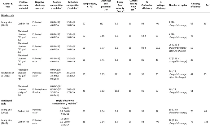
Divided cells use two different electrolytes, one for each half-cell. Leung et al used 0.8 mol dm−3 Ce(III) dissolved in 4.0 mol dm−3 MSA for the positive half-cell and 1.5 mol dm−3 Zn(II) in 1.0 mol dm−3 MSA for the negative half-cell. [33, 34]. The difference in the composition of the electrolyte allowed ions to migrate through the membrane into the negative half-cell, which
altered the performance of the cell and constituted a limiting factor to its service-life. Nikiforidis
et al used a slightly lower concentration of cerium in the positive half-cell electrolyte, 0.59 mol
32
is more concentrated that in the previous work. Discharge results for these divided and
undivided cells are presented in Table 7.
Undivided cells could solve some of the issues found in divided cells by the use of only one
electrolyte containing both redox species. Leung et al prepared a single electrolyte consisting of
0.2 mol dm−3 Ce(III), 1.5 mol dm−3 Zn(II) and 0.5 mol dm−3 of MSA [69,86]. The low acid concentration in this case minimised the HER and facilitated the electrodeposition of zinc. The
cerium concentration was also kept low as well as otherwise, the zinc electrodeposition
overpotential increased significantly due to competition with Ce(IV) ions at the electrode
surface. As shown in Table 7, coulombic and energy efficiencies were higher than those
obtained with some divided cells. Nevertheless, the low cerium concentration meant that the cell
had a relatively poor energy density (ca. 11 W h dm–3).
The use of mixed acid electrolytes has been proposed to solve some of the limitations of the
current Zn-Ce RFBs. Xie et al reported an increment of the cerium species solubility and
enhanced reversibility of the cerium reaction when a mixture of 2.0 mol dm−3 MSA and 0.5 mol dm−3 sulphuric acid was used to dissolve 0.3 mol dm−3 of Ce(III) [87, 88]. The coulombic and energy efficiencies of this cell are 87.1 % and 73.5 %, respectively. The effect of sulfuric acid on
the stability of the carbon-based electrodes in the most advanced laboratory cells has yet to be
investigated. On the other hand, mixed acid media can be detrimental to undivided cells, by
diminishing the efficiency of both cerium reaction and zinc electrodeposition due to the high
proton concentration [86]. Nikiforidis and Daoud [89] recently published a study of
hydrochloric, sulfuric and nitric acids for mixed acid electrolytes for the Zn-Ce RFB. These
33
Ce(III) and 4.0 mol dm−3 of MSA has an significant positive effect on the reversibility and kinetics of the cerium redox reaction for temperatures ranging from 25 ºC to 55 ºC. While
sulfuric acid (0.5 to 2 mol dm−3) in the electrolyte also produced higher exchange current densities and diffusion coefficients, the reversibility of the reaction did not improve.
Electrolytes containing nitric acid (0.5 to 2 mol dm−3 HNO3 + 4 M MSA) were found to be unsuitable.
Alternatives to MSA as supporting electrolytes have also been suggested. A Zn-Ce test cell with
sulfamic acid media yielded a coulombic efficiency of 90 % [90]. Xie et al presented kinetic data
for the cerium reaction in a mixture of sulfosalicylic and sulphuric acid, although this option has
not been tested in a flow cell [91]. Modiba et al proposed a different cerium RFB in which
cerium in sulphuric acid is used in both half-cells, in a way comparable to the vanadium system
[56, 92-94]. This can be achieved by use of cerium species complexed with
diethylenetriaminepentaacetic acid (DTPA) in one side of the membrane. The reported
improvement of the cerium reaction kinetics when complexed with DTPA suggests that the
addition of such complexing agents in Zn-Ce RFBs could prove beneficial. The stability of
DTPA and similar substances in MSA electrolytes has to be investigated further though under
operational conditions. Preliminary tests by Xie et al showed a positive effect of DTPA [88].
4.3 Electrodes
The composition of electrodes plays a crucial role in the performance of RFBs, particularly in
the Zn-Ce system. Electrodes have to withstand strong acid conditions at relatively high
temperatures (>50 ºC). In addition, the positive electrode has to operate under the oxidizing
34
materials during the early stages of development. Nevertheless, it was also clear that
carbon-based materials offered a much cheaper and practical option, either as plates, felts or foams, all
of which are widely available in the electrochemical industry. As discussed in the next section,
evidence seems to point in the direction of carbon based materials as the best option for the
Zn-Ce RFBs. Inevitably, inclusion of polymer particles in composite electrodes decreases the
conductivity compared to graphite and may give rise to feeder contact problems [85] but
provides a practical, robust carbon-polymer composite for use in larger cells. The use of certain
carbon felt electrodes may avoid the need for expensive platinum coatings for positive electrodes
but careful choice and preparation of such materials is needed as well as adequate attention to
full backplate feeders to distribute the current density as evenly as possible over the 3-D
electrode surface.
4.3.1 Positive electrode
Several positive electrode materials have been tested in a divided RFB, including platinized
titanium, graphite, carbon polyvinyl ester, reticulated vitreous carbon and carbon felt [34]. Of
these, platinized titanium meshes (Pt loading: 70 g m−2) and some carbon felts were found suitable for Zn-Ce RFBs, showing the highest discharge current densities. In these conditions
platinized titanium electrodes yielded coulombic and voltage efficiencies of 99.4 % and 59.6 %,
respectively, at a current density of 50 mA cm−2 (Table 1B). Favourably, the performance of the carbon felt electrodes was very close to the platinum materials, with coulombic and energy
efficiencies of 92 % and 63 % respectively. This indicates that certain carbon felts might be used
instead of noble metal substrates as positive electrodes, greatly reducing the cost of a Zn-Ce
RFB system. A method to improve the binding of the carbon felt to its substrate (graphite plate)
has to be found in order to reduce the ohmic loses and increase the durability of the electrode.
35
efficiency of 76 % [69, 86]. The felts were pressed onto a polyvinyl ester-carbon plate. Other
examples of carbon felt use can be found in the cells used by Xie et al [87] and Xiong et al [90]
for the evaluation of acid electrolyte alternatives. The presence of uncoated parts of carbon
electrode surfaces, however, requires care due to possible oxidation. Ce(IV) oxidation of carbon
is a key reason titanium sheets were used as current collectors and normally compression was
employed to provide contact between the backplate and the 3-D electrode as adhesives suffer
from long-term degradation and conductance problems.
Similar results were obtained using platinized titanium mesh as the positive electrode in another
divided cell [85]. The highest values for coulombic and energy efficiency were 90 % and 64 %,
respectively. It is worth noting that the Pt content was lower (only 10 g m−2) than in the cell mentioned above, yet the performance was almost the same. This indicates that a relatively thin
Pt coating is sufficient to provide high current densities, at least in short term trials.
A recent electrochemical evaluation of different Pt-based metallic coatings on Ti substrates as
positive electrode materials for the Zn-Ce system suggest that the presence of a Pt-Ir coating
increased the kinetics of the Ce(III)/(IV) reaction substantially. This was especially so at
elevated temperatures where increases in the exchange density by factors of ca. 40 100 were
measured over the temperature range 25 °C to 60 °C [95, 96]. This was aided in no small part by
the large specific electrochemical area of the order of ~100 cm2 mg1 and ~40 cm2 mg1 achieved by the Pt-Ir and Pt coatings, respectively. Clearly then, for commercial exploitation,the
investigation of practical catalyst-modified carbon felts as positive electrodes is an important
36 4.3.2 Negative electrode
Nikiforidis et al has published two electrochemical studies of several carbon-based materials as
negative electrodes in the Zn-Ce RFB [70, 97]. Carbon-polyvinyl ester, polyvinylidene fluoride,
high-density polyethylene, glassy carbon, and graphite foil were considered. It was found that
carbon polyvinyl ester-carbon and polyvinylidene fluoride-carbon composites exhibited high
coulombic efficiencies and maintained their integrity over more than 200 charge/discharge
cycles. These materials were used in flow battery studies, where they exhibited coulombic
efficiencies of 90 % and 81 %, respectively [85]. Carbon-polyvinyl ester was superior to
polyvinylidene fluoride, with an energy efficiency of 64 % vs. 61 %.
One of the major factors impacting on the voltage efficiency (and so energy efficiency) of the
RFB in the design used by Nikiforidis et al [85] has been the resistance of the negative electrode.
The carbon composite plates are attached to the electrode holder (e.g. Ti base plate) using a
variety of conducting media (such as Leit-C conductive carbon cement, Plano Gmbh or silver
conductive paint, RS Components) and pressure was applied to provide a good ohmic contact.
Preparation of the adjoining surfaces, viz. via mechanical roughening of the carbon composite
and surface oxide film removal of the base plate by acid or other etching procedure has to be
carefully carried out in order to ensure that the area resistance of the electrode is of the order of
0.02 cm2 or less. It may well be that better performance could be achieved by direct thermal bonding of the composites to the base plate.
The divided and undivided cells reported by Leung et al used polyvinyl ester plates as the
negative electrode [33, 34, 69, 86]. Zinc electrodeposition on this material was previously
studied in a parallel flow cell under different zincate and acid concentrations and over a range of
37
observed. No degradation was reported during the operation of the divided RFBs, which is in
accordance with materials testing carried out by Nikiforidis et al [26].
Some divided cells in the literature have used the convenience of zinc plates as the negative
electrode to eliminate any effects from the negative electrode in experiments where the
conditions in the positive half-cell were studied [87, 90].
4.4 Operational variables 4.4.1 Temperature
Charge/discharge performance of divided Zn-Ce RFBs shows improvement at relatively elevated
temperatures. Cells tested in the temperature range of 25 ºC to 60 ºC showed that voltage and
charge efficiencies increase along with temperature [34, 85]. The same effect could be seen with
the energy efficiency. After evaluating other parameters, an operating temperature of 50 ºC was
selected as the most adequate. The coulombic efficiency fell significantly at the lowest
temperature, while the optimal temperature had a different value for each of two negative
electrode materials, 55 ºC and 45 ºC for polyvinyl ester and polyvinilydene fluoride composites,
respectively. These effects can be explained by faster kinetics and increments in the diffusion
coefficient due to a reduction in electrolyte viscosity [95].
The relationship between performance and temperature was quite different for an undivided cell,
where charge efficiencies decreased with increasing temperature [69, 86]. The optimum
performance of the undivided system was found to be at room temperature (23 ºC), which could