Clarke, J.A. and Conno, G. and Grant, A.D. and Johnstone, C. (2009)
Development and in-sea performance testing of a single point mooring
supported contra-rotating tidal turbine. In: 28th International Conference
on Ocean, Offshore and Arctic Engineering, OMAE 2009, 2009-05-31 -
2009-06-05, Hawaii, USA. ,
This version is available at
https://strathprints.strath.ac.uk/16324/
Strathprints is designed to allow users to access the research output of the University of Strathclyde. Unless otherwise explicitly stated on the manuscript, Copyright © and Moral Rights for the papers on this site are retained by the individual authors and/or other copyright owners. Please check the manuscript for details of any other licences that may have been applied. You may not engage in further distribution of the material for any profitmaking activities or any commercial gain. You may freely distribute both the url (https://strathprints.strath.ac.uk/) and the content of this paper for research or private study, educational, or not-for-profit purposes without prior permission or charge.
Any correspondence concerning this service should be sent to the Strathprints administrator:
Clarke, J.A. and Conno, G. and Grant, A.D. and Johnstone, C. (2009) Development and in-sea performance
testing of a single point mooring supported contra-rotating tidal turbine. In: 28th International Conference
on Ocean, Offshore and Arctic Engineering, OMAE 2009, 31 May - 5 June 2009, Hawaii, USA.
http://strathprints.strath.ac.uk/
16324
/
Strathprints is designed to allow users to access the research output of the University of
Strathclyde. Copyright © and Moral Rights for the papers on this site are retained by the
individual authors and/or other copyright owners. You may not engage in further
distribution of the material for any profitmaking activities or any commercial gain. You
may freely distribute both the url (
http://strathprints.strath.ac.uk
) and the content of this
paper for research or study, educational, or not-for-profit purposes without prior
permission or charge. You may freely distribute the url (
http://strathprints.strath.ac.uk
)
of the Strathprints website.
Proceedings of the ASME 28th International Conference
on Ocean, Offshore and Arctic Engineering
OMAE2009
May 31 - June 5, 2009, Honolulu, Hawaii
Paper No. OMAE2009-79995
DRAFT
DEVELOPMENT AND IN-SEA PERFORMANCE TESTING OF A SINGLE POINT MOORING
SUPPORTED CONTRA-ROTATING TIDAL TURBINE
Joe Clarke
Energy Systems Research Unit, Dept. of Mechanical Engineering, University of
Strathclyde, Glasgow, Scotland, UK
Andrew Grant
Energy Systems Research Unit, Dept. of Mechanical Engineering, University of
Strathclyde, Glasgow, Scotland, UK
Gary Connor
Energy Systems Research Unit, Dept. of Mechanical Engineering, University of Strathclyde, Glasgow, Scotland, UK
Cameron Johnstone
Energy Systems Research Unit, Dept. of Mechanical Engineering, University of Strathclyde, Glasgow, Scotland, UK
ABSTRACT
A 2nd generation, contra-rotating marine current turbine has been developed by the Energy Systems Research Unit at the University of Strathclyde. This system can be tuned to extract energy over a wide range of water depths by “flying” a neutrally-buoyant device from a flexible, tensioned mooring. After successful proof of concept turbine trials, the development programme has moved on to investigate the performance of a scaled prototype system comprising of a dual rotor, contra-rotating turbine directly coupled to a submersible contra-rotating generator; and held on station via a gravity based tensioned mooring system. The turbine/generator assembly was initially tested in a towing tank, before the entire system underwent sea trials initially at the Kyles of Bute in the River Clyde Estuary before being deployed in eth Sound of Islay of eth West Coast of Scotland.
An investigation into turbine wake development (an area in which it is hoped that the contra-rotating turbine will have uniquely beneficial properties) has
recently begun. Small single-rotor model turbines have been deployed in a flume. Trends observed so far are in accordance with those observed by other researchers.
1. INTRODUCTION
2
The early stages of marine current exploitation are likely to be served by 1st generation turbine technologies on fixed piles [3] or gravity base structures, but if the full benefits from the resource are to be gained and larger scale commercial deployment is to be undertaken, it will be necessary at some stage to deploy larger machines in deeper water using lower cost flexible, single riser, tensioned moorings.
The ESRU contra-rotating turbine is specifically designed for such a mooring system and as such is widely regarded as a “second-generation” device. Its operation hinges on the principle of “flying” a neutrally-buoyant turbine from a single-point mooring. There are issues relating to stability and station-keeping in streams with variable speed and direction, and these are presently under investigation. However, initial results are highly positive showing great stability being maintained. Studies of a prototype system in a towing tank then in real sea conditions will be described in this paper.
A second feature of the ESRU turbine which follows from minimising reactive torque of the supporting system is the reduction of swirl in the wake. This touches on an issue which will assume increasing importance as the deployment of increasing numbers of full-scale marine current turbines within tidal farms progresses: namely, the influence of wakes on the performance of turbine arrays and, more importantly, the packing density. Experiences with wind farm design are of limited value given the differences in fluid properties and boundary conditions. It is widely accepted [4] that wake-turbine interaction may prove to be a major limiting factor in the exploitation of coastal sites.
A contra-rotating turbine may to some extent alleviate this problem. There is evidence from studies on helicopter rotors [5] that a contra-rotating machine produces a fundamentally different wake structure, with more favourable dissipation characteristics. The present state of knowledge is far from complete; the problem stretches mathematical modelling techniques to the limit. However, prediction methods for turbine wake development are the subject of intensive research, and signs of progress are encouraging [6].
Reliable experimental data are hard to find: few facilities exist for investigating flow through turbine arrays, even at very small scales. A small number of investigations have been made in recent years; more are clearly needed.
2. EXPERIMENTAL TURBINES
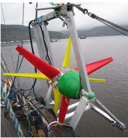
After successful proof of concept trials on a 0.9 m diameter contra-rotating turbine in a towing tank [1], a larger 2.5 m diameter prototype was constructed (see Figure 1).
[image:4.595.316.526.291.518.2]Sea trials in the Clyde estuary confirmed the inherent stability of the contra-rotating design and for the first time provided high-resolution measurements of blade bending moments, from strain gauges attached to blade roots on both rotors. Of particular interest was the loading on the downstream blades, as the turbine configuration inevitably raises questions about blade/blade interactions and consequent fatigue loading.
Figure 1: Prototype contra-rotating marine turbine being deployed in the Sound of Islay
Figure 2 gives time-series data for the turbine during normal operation, with both rotors turning at similar (but not identical) speeds. Because the upstream rotor has 3 blades, blade/blade interaction in the turbine would be expected to manifest itself as pulses at a frequency of 3(f1+f2), where f1 and f2 are the
Figure 2: Time-series blade bending moment data for upstream (R1) and downstream (R2) rotors, to
an arbitrary scale; normal operation
0 5 10 15 20 25 30
0 1 2 3 4 5 6 7 8
Frequency (P)
A
m
p
li
tu
d
e
No window Hanning
Figure 3: FFT for rear blade thrust loading during normal contra-rotating operation.
By contrast, a time series was obtained when the upstream rotor was deliberately stalled (Figure 4). This clearly shows large regular shock loadings on the downstream blade as it passes through the bluff body wake created by the stationary blades upstream.
[image:5.595.309.524.104.281.2]When viewed together, Figures 2 and 4 give some perspective on the magnitude of cyclic loads during normal operation of the turbine. The spectrum is dominated by gravitational loads and the wakes behind fixtures, which can be minimised by careful design. In contrast, blade/blade interactions are relatively very small indicating a reduction in dynamic fatigue loading thus increasing operational life expectancy
Figure 4: Time-series blade bending moment data for upstream (R1) and downstream (R2) rotors, to
an arbitrary scale; R1 stalled
3. MOORING CONSIDERATIONS
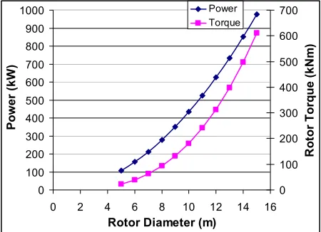
The torque produced by a turbine and the resultant power capture is largely proportional to the swept area and hence diameter of the turbine. This in turn will influence the type of supporting structure used to keep the device on station. For a conventional 1st generation single rotor turbine, operating in a designed tidal velocity of 3 ms-1, a power coefficient of 0.4 and a blade tip velocity ratio ( ) of 4; Figure 5 identifies the power rating and resulting torque on the rotor, and reactive torque absorbed by the supporting structure as the rotor diameter increases.
0 100 200 300 400 500 600 700 800 900 1000
0 2 4 6 8 10 12 14 16
Rotor Diameter (m)
Po
w
e
r
(k
W
)
0 100 200 300 400 500 600 700
R
o
to
r
T
o
rq
u
e
(
k
N
m
)
Power Torque
[image:5.595.56.273.353.478.2] [image:5.595.309.534.516.679.2]4
These high levels of torque make it very difficult for a 1st generation, single rotor turbine to be supported by a tensioned, single riser mooring system and provide good station keeping properties.
[image:6.595.309.543.148.327.2]The ESRU contra-rotating turbine has specifically been designed to neutralise the reactive torque and facilitate operation from a tensioned, single riser mooring secured to the sea-bed. One problem is to provide sufficient buoyancy to maintain the operating depth of the turbine between reasonable limits; even at small scales this is not easy to accomplish. The simplest method is to employ an auxiliary float (Figure 6).
Figure 6: Neutrally-buoyant turbine on a tensioned cable.
Here the turbine itself would have near-neutral buoyancy with the excess provided by the tensioning float. For the lower part of the cable, static analysis
simplifies to the equation
B FD
= φ
tan , but in
this case FD is the summation of the drag forces on
the turbine and float; the latter may be quite substantial. It can be reduced significantly by placing the float on the surface, if excitation by waves is not a problem.
The intention with this configuration would be to operate at small values of φ by building in greater excess buoyancy. Variations in operating depth with current velocity V would then be significantly reduced.
As identified by Betz [12], when a turbine operates at its maximum Cp the drag coefficient of the rotor equates to 8/9. Figure 7 demonstrates the drag created and buoyancy forces required in order to prevent angle exceeding 40º when a turbine
operates at its maximum rated power capture in a tidal stream velocity of 3 ms-1.
0 100 200 300 400 500 600 700 800
0 2 4 6 8 10 12 14 16 Rotor Diameter (m)
[image:6.595.65.268.275.439.2]D ra g F o rc e ( k N ) 0 100 200 300 400 500 600 700 800 900 1000 B u o y a n c y F o rc e ( k N ) Drag Buoyancy
Figure 7: Drag and buoyancy forces relative to rotor diameter (tidal velocity = 3 ms-1)
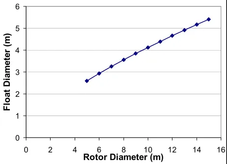
The effects of these forces and the scaling may have an influence on the choice of single riser mooring configuration and fixing to the sea bed. Drag forces rise approximately with the square of the linear dimension, whereas buoyancy increases with the cube. Figure 8 illustrates this with regard to a spherical surface float or floatation chamber.
0 1 2 3 4 5 6
0 2 4 6 8 10 12 14 16
Rotor Diameter (m)
F lo a t D ia m e te r (m )
Figure 8: Float diameter versus turbine diameter (maximum tidal velocity = 3 ms-1).
While it is possible to make the rotor and nacelle to have near-neutral buoyancy, the active material weight of the Permanent Magnet Generator (PMG) is likely to be the most significant part-mass of the
[image:6.595.302.533.477.644.2]turbine. The PMG mass may be calculated by rearranging equation (1): where J is the conductor maximum current density, rI is the inner core radius, rO is the outer core radius, B is the average flux
density in the winding, n is the rotational speed, and
a is the winding axial thickness.
(
2 2)
2
.
.
.
4
J
r
IB
n
a
r
Or
IP
=
π
−
(1)rO was set to be √3 rI thus optimising the power for a
given outside diameter and loading [7]. This is unlikely to be an optimal mechanical or economic design, but allows sufficient radius information to estimate the weight of a PMG. This was added to the calculation for buoyancy used to produce Figure 8.
There are a number of issues pertaining to the use of these moorings for marine current turbines which require further investigation. One of course is the behaviour at slack water, where the turbine must avoid fouling the mooring, and re-align itself when the current starts to flow. A number of solutions are possible including motoring a main rotor or the use of modified marine thrusters to provide additional yaw control.
Another issue is cable twist: repeated uni-directional circular motions of the device about its tethering point would eventually damage the electrical power cable, which must necessarily follow the route of the main riser to the sea bed. The aforementioned yaw mechanism could provide an unwind function, or a slip-ring style electrical coupling could be employed – the life-cycle duty of such a mechanism being very small compared to that used in high-speed machinery.
Yet another issue is stability in turbulent flows: tests by the authors on small models in flumes (only qualitative so far) and in the sea trials of a scaled prototype device. The testing undertaken in the flume indicated that the shape of the nacelle may be an important factor. With some shapes, oscillations in yaw or pitch seem to occur despite the large self-aligning effect of the drag force on the rotor itself.
4. SCALED PROTOTYPE SYSTEM
The “proof of concept” approach has been extended recently to cover the complete system: contra-rotating turbine, generator and tensioned mooring. A scaled prototype has been constructed, for sea trials to demonstrate the following features:
• the performance of a complete contra-rotating power train;
• the production of electricity from a submerged generator; and
• the stability of the complete system on a single-point mooring.
Figure9: Rendering of scaled prototype nacelle.
The turbine uses a direct-drive generator, resulting in a large nacelle diameter. There was also a demand for a reasonably high rotational speed, which imposed limits on overall rotor diameter. The result was a turbine with hub diameter 0.43m and overall diameter 0.92m. The complete turbine is illustrated as a cut-away drawing in Figure 9 and demonstrated as a system being deployed for in-sea testing in Figure 12.
Despite the bulky nacelle, it was found to be difficult at this scale to go much beyond neutral buoyancy and a tensioned cable with auxiliary float (Figure 6) was adopted for the trials.
It has been recommended that the generator diameter should not be greater than 10% of the rotor diameter for wind turbines [7], however it is presently unknown whether this holds for tidal machines. Options exist to reduce the diameter of the generator:
• Several axial generator units may be connected in series on the same frame, • The electrical output may be generated at a
lower frequency and converted to that required, although core copper losses increase significantly at very low frequencies [8]
Contra-rotating
Generator
Buoyant
Cone
Contra-rotating
Blades
Spine
Buoyant
6
5. DIRECT DRIVE GENERATOR
The relatively slow prime mover rotational speed of a tidal turbine necessitates a gearbox to increase the speed suitably for a common four-pole generator. Another option is a direct drive generator with a large number of poles. This has the distinct advantages of: a higher overall power take off efficiency of typically 90% near rated load [9] compared to around 85% for a costly multi-stage high torque gearbox (4-stage efficiency of 94%) and generator (90%) combination [10]; greater reliability; and a diminished maintenance requirement.
The manufactured direct drive generator has an axial magnetic field created by 24 Neodymium-Iron-Boron (Nd-Fe-B) N50 grade permanent magnets distributed on the 2 rotors making up 12 magnetic poles, and sandwiching the stator which contains 9 copper windings encased within a polymer resin disk. Nd-Fe-B magnets have vastly superior magnetic properties over traditional Ferrite magnets. The remanence flux density Bτ of the chosen magnets is
1.42T. The maximum operating temperature (150
oC) of Nd-Fe-B magnets is unlikely to be an issue in
a submerged tidal generator.
The axial-flux generator is configured to provide a 3-phase electrical output. This is converted to DC via a 3-phase rectifier. The energy may therefore be efficiently transmitted underwater and inverted at the grid end, or in this experimental case, fed into a resistive dumped load by a Pulse Width Modulated (PWM) driven Insulated Gate Bipolar Transistor (IGBT) allowing the turbine microcontroller to regulate the overall turbine speed and attain maximum Cp throughout the tidal cycle. The contra-rotating prime mover torque balance critical to maintaining the zero reactive torque and thus providing turbine hydrodynamic stability is provided inherently by the magnetic flux linkage across the stator-rotor air gap. The machine as constructed is illustrated in Figures 10 and 11.
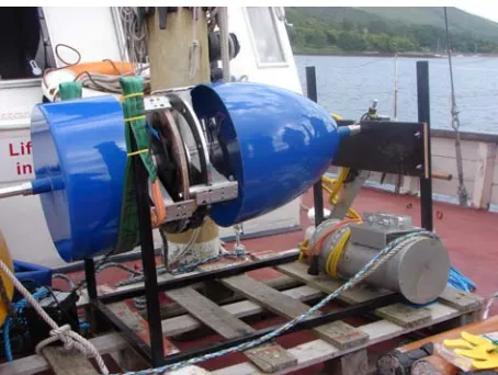
[image:8.595.308.536.100.275.2]In addition it was decided to experiment with a submersible generator, that is, the rotors and stator both operate in sea-water. Although the magnetic properties of sea-water and air are not significantly different, the electrical insulating properties and corrosive abilities certainly are. The rotors and nickel coated permanent magnets are therefore coated in a hard wearing polymer to provide corrosion protection.
Figure 10: Encapsulated coils and permanent magnets of contra-rotating axial flux generator
Figure 11: Generator location within the turbine nacelle
The stator is constructed from polyurethane resin into which the copper coils are hermetically sealed with glands allowing the electrical output cables to exit the generator. The advantages of a generator open to seawater are:
• ease of construction,
• generator/nacelle casing leaks are non issues,
• cooling is naturally provided, • no complex sealing requirements, • no large diameter seal friction.
Possible drawbacks are:
[image:8.595.308.535.327.498.2]• marine growth on exposed stationary components.
The first drawback is partly mitigated by the relatively low rotational speeds and the hydrodynamically efficient design of the exposed parts. Marine growth may be mitigated against by the high levels of water turbulence experienced, speed of rotation, the use of anti-fouling compounds or a mechanical ‘wiper’ system on the active generator surfaces.
6. SCALED PROTOTYPE TESTING
[image:9.595.310.559.144.286.2]In-sea testing of a scaled prototype system has been undertaken in the last quarter of 2008 (Figure 12).
Figure 12: Trial deployment of scale prototype
Trial deployment and recovery of the gravity base, buoy and mooring has been successfully accomplished, and stability trials of the turbine assembly have been conducted both in a towing tank then at sea.
Some measurements from the towing trials are shown in Figure 13. The generator output voltage indicates the duration of the towing period. The turbine nacelle is fitted with inclinometers to monitor its attitude in the flowing stream. Measurements indicated excursions in pitch and roll up to 15° from nominal, possibly in response to turbulence downstream from a rather heavy towing strut. But the stability of such a bulky device (hub diameter almost 50% of the overall diameter) is likely to be poor; the more elegant proportions of larger,
[image:9.595.62.289.294.500.2]production turbines should confer more sedate behaviour.
Figure 13: Results from towing tank trials
But this remains to be seen. The scaled prototype system has been deployed at sea, for evaluation over full tidal cycles. The nacelle attitude, mooring loads, rotor speeds and electrical output was monitored continuously over the test period. Figure 14 provides data on the roll and pitch of the prototype device supported by a single riser mooring during the sea trials. This shows the device to be relatively stable during operation, with turbine roll not exceeding 3° and pitch not exceeding 1.5°. This makes it ideal for using a single riser mooring support system for station keeping, resulting in the mooring system only having to accommodate the resulting drag and buoyancy forces enacting on it.
Figure 14: Roll and pitch results from in-sea testing.
It should be emphasised that a good peak hydrodynamic efficiency is not essential to achieving the aims of the test programme. Performance of the
-2 -1.5 -1 -0.5 0 0.5 1 1.5 2 2.5 3 3.5
0 500 1000 1500 2000 2500 3000 3500
Time (seconds)
D
e
g
re
e
s Turb Pitch (deg)
Turb Roll (deg)
-20 -10 0 10 20 30 40 50
0 20 40 60 80 100
Time (seconds)
[image:9.595.299.551.498.657.2]8
contra-rotating turbine was compromised to some extent by the decision to use existing blades in the interests of saving time, whose chord and pitch distributions had originally been optimised to suit a different set of parameters. Predictions of power and thrust coefficients (CP and Ct) for the complete
2-rotor machine are given in Figure 15. The project is essentially a “proof of concept” exercise.
0 0.1 0.2 0.3 0.4 0.5 0.6
2 4 6 8 10
Tip speed ratio
[image:10.595.71.267.208.431.2]Cp Ct
Figure 15: Performance predictions for turbine to be used in full system sea trials.
The tip speed ratio at which peak CP is achieved
reflects the geometric limitations imposed on the design; a higher value would perhaps have been desirable.
7. CONCLUSIONS
The ESRU marine current turbine development programme is continuing with investigations into the performance of a scaled prototype of the complete system, including a submersible contra-rotating generator and tensioned moorings. The prototype has been constructed, and trials carried out on individual components; and the complete system has undergone sea trials off the West coast of Scotland. Turbine station keeping in real sea conditions, in terms of pitch and roll, has been demonstrated to be very stable. The viability of using a single riser mooring system has been demonstrated, the forces acting on this identified, and a good correlation between predicted and actual forces achieved. The results from the turbine tests and single riser mooring
assessments will enable the developers to produce a robust single riser mooring system and commercial sized turbine for large scale demonstration purposes.
9. REFERENCES
[1] Clarke J A, Connor G, Grant A D and Johnstone C M. Design and initial testing of a contra-rotating tidal current turbine. Proc 6th European Wave and Tidal Energy Conference (2005), Glasgow, UK.
[2] Clarke, J A, Connor, G, Grant, A D and Johnstone, C M. Design and testing of a contra-rotating tidal current turbine. Proc I Mech E Part A, Journal of Power and Energy, 221, 2, pp 171-179, Professional Engineering Publishing, 2007. ISSN 0957-6509.
[3] www.marineturbines.com
[4] Myers L and Bahaj A J. Wake studies of a 1/30th scale horizontal axis marine turbine. Ocean Engineering 34 (2007), pp 758-762.
[5] Kim H W and Brown R E. Coaxial rotor performance and wake dynamics in steady and manoeuvring flight. American Helicopter Society 62nd Forum (2006), Phoenix, Arizona, USA.
[6] McCombes T, Grant A, Johnstone C: Wake modelling for marine current turbines. 2nd International Conference on Ocean Energy, Brest, France, October 2008.
[7] Soderlund L, Eriksson J T, Salonen J, Vihriala H, Perala R. A Permanent-Magnet Generator for Wind Power Applications, IEEE Transactions on Magnetics, Vol. 32, No. 4, July 1996.
[8] Segergren E, Nilsson K, Leijon M. Frequency Optimisation with Respect to Weight and Electrical Efficiency for Direct Drive Underwater Power Generator. IEEE Journal of Oceanic Engineering, November 2004.
[9] Nilsson K, Segergren E, Sundberg J, Sjostedt E, Leijon M. Converting Kinetic Energy in Small Watercourses Using Direct Drive Generators. Proceedings of OMAE04 23rd International Conference on Offshore Mechanics and Arctic Engineering (2004), Vancouver, British Columbia, Canada.
Wind Turbines, 21st American Society of Mechanical Engineers (ASME) Wind Energy Symposium, Reno, Nevada, January, 2002.