UNIVERSITI TEKNIKAL MALAYSIA MELAKA
MODELLING EFFECT OF CUTTER GEOMETRICAL FEATURE
FOR SHOULDER MILLING OF THIN DEFLECTING WALL
This report submitted in accordance with requirement of the Universiti Teknikal Malaysia Melaka (UTeM) for the Bachelor Degree of Manufacturing Engineering
(Manufacturing Process) (Hons.)
by
HELMI AFFENDI BIN MOHAMAD AZMI
B051110291
880331-56-5451
UNIVERSITI TEKNIKAL MALAYSIA MELAKA
BORANG PENGESAHAN STATUS LAPORAN PROJEK SARJANA MUDA
TAJUK: MODELLING EFFECT OF CUTTER GEOMETRICAL FEATURE FOR SHOULDER MILLING OF THIN DEFLECTING WALL
SESI PENGAJIAN: 2013/14 Semester 2
Saya HELMI AFFENDI BIN MOHAMAD AZMI
mengaku membenarkan Laporan PSM ini disimpan di Perpustakaan Universiti Teknikal Malaysia Melaka (UTeM) dengan syarat-syarat kegunaan seperti berikut:
1. Laporan PSM adalah hak milik Universiti Teknikal Malaysia Melaka dan penulis. 2. Perpustakaan Universiti Teknikal Malaysia Melaka dibenarkan membuat salinan
untuk tujuan pengajian sahaja dengan izin penulis.
3. Perpustakaan dibenarkan membuat salinan laporan PSM ini sebagai bahan pertukaran antara institusi pengajian tinggi.
4. **Sila tandakan ( )
SULIT
TERHAD
TIDAK TERHAD
(Mengandungi maklumat yang berdarjah keselamatan atau kepentingan Malaysia sebagaimana yang termaktub dalam AKTA RAHSIA RASMI 1972)
(Mengandungi maklumat TERHAD yang telah ditentukan oleh organisasi/badan di mana penyelidikan dijalankan)
Alamat Tetap:
23 Laluan Desa Tambun 4,
Taman Desa Tambun,
31400 Ipoh, Perak.
Tarikh: ________________________
Disahkan oleh:
Cop Rasmi:
Tarikh: _______________________
DECLARATION
I hereby, declared this report entitled “Modelling Effect of Cutter Geometrical Feature for Shoulder Milling of Thin Deflecting Wall” is the results of my own research except as cited in references.
Signature :……….
Author’s Name : HELMI AFFENDI BIN MOHAMAD AZMI
Date :23 JUNE 2014.
APPROVAL
This report is submitted to the Faculty of Manufacturing Engineering of UTeM as a partial fulfillment of the requirements for the degree of Bachelor of Manufacturing Engineering (Manufacturing Process). The member of the supervisory committee is as follow:
………. Dr. Raja Izamshah Bin Raja Abdullah
i
ABSTRAK
ii
ABSTRACT
iii
ACKNOWLEDGEMENT
iv
TABLE OF CONTENT
Abstrak i
Abstract ii
Acknowledgement iii
Table of Content iv
List of Tables viii
List of Figures ix
List Abbreviations, Symbols and Nomenclatures xi
CHAPTER 1: INTRODUCTION 1
1.1 Research Background 1
1.2 Problem Statement/ Current Technique in Machining Thin-Wall 3
1.3 Objectives 4
1.4 Scope of Project 5
CHAPTER 2: LITERATURE REVIEW 6
2.1 Introduction 6
2.2 Thin Wall Machining 6
2.2.1 Shoulder Milling 7
2.2.2 Milling Thin-Walls 8
2.2.3 Milling Thin Bases 10
2.2.4 Cutting Medium 11
2.2.5 Thin-Wall (Workpiece) Material 12
2.3 Cutting Tool 13
2.3.1 End Mill 13
2.3.1.1 Two-Flute End Mills 13
2.3.1.2 Three-Flute End Mills 14
v
2.3.2 End Mill Geometrical Feature 15
2.3.3 Importance of Helix Angle on End Mill Geometrical Feature 16
2.3.4 Cutting Tool Material 17
2.4 Finite Element Analysis 18
2.4.1 Modeling, Simulation and Prediction 19
2.4.2 Deflection When Machining Thin-Wall Part 20
2.4.3 Modelling On DEFORM-3D 21
CHAPTER 3: METHODOLOGY 22
3.1 Introduction 22
3.2 Research Flow Chart 22
3.3 Cutter Geometrical Feature 25
3.4 Thin-Wall Component 25
3.5 Design of Experiment (DOE) 26
3.6 Part Modeling 27
3.7 Finite Element Analysis (FEA) 28
3.7.1 Mesh Types 29
3.7.2 Mesh Size 29
3.7.3 Boundary Conditions 31
3.7.4 Contact Conditions 32
3.7.5 Other Finite Element Condition 33
3.7.6 Simulations 34
3.8 Experimental Setup 34
CHAPTER 4: RESULTS AND DISCUSSIONS 37
4.1 Introduction 37
4.2 Surface Error 38
4.2.1 Run 1 (2 flute 45° helix angle of end mill with 2.5 mm wall thickness and 25
mm wall height of thin-wall) 39
4.2.2 Run 2 (3 flute 45° helix angle of end mill with 1.5 mm wall thickness and 30
vi 4.2.3 Run 3 (3 flute 35° helix angle of end mill with 2.5 mm wall thickness and 35 mm
wall height of thin-wall) 40
4.2.4 Run 4 (4 flute 25° helix angle of end mill with 2.5 mm wall thickness and 30 mm
wall height of thin-wall) 41
4.2.5 Run 5 (4 flute 35° helix angle of end mill with 1.5 mm wall thickness and 25 mm
wall height of thin-wall) 42
4.2.6 Run 6 (2 flute 35° helix angle of end mill with 2 mm wall thickness and 30 mm
wall height of thin-wall) 43
4.2.7 Run 7 (2 flute 25° helix angle of end mill with 1.5 mm wall thickness and 35 mm
wall height of thin-wall) 43
4.2.8 Run 8 (3 flute 25° helix angle of end mill with 2mm wall thickness and 25mm wall
height of thin-wall) 44
4.3 Simulation Validation 44
4.3.1 Simulation (Predicted) Surface Error 46
4.3.2 Experiment Surface Error 47
4.3.3 Surface Error Comparison 48
4.4 Statistical Analysis of Experimental Data 52
4.4.1 Statistical Design Matrix 52
4.4.2 Statistical Output Analysis 53
4.4.2.1 ANOVA Output 53
4.4.2.2 Residual Analysis 54
4.4.2.3 Response Surface 56
4.4.3 Optimization and Validation 56
CHAPTER 5: CONCLUSION AND RECOMMENDATION 60
5.1 Conclusion 60
5.2 Recommendations 61
vii APPENDICE
viii
LIST OF TABLES
2.1 Cutting parameter 12
3.1 Fix parameter used 25
3.2 Variable cutter geometrical feature used 25
3.3 Material and geometry of the thin-wall component 26 3.4 Process controls parameters and their limits 26 3.5 Design of experiment (DOE) for finite element analysis 27
3.6 Other finite element condition for workpiece 33
3.7 Other finite element condition for tool 33
3.8 Machining parameters used for simulation and experiment 36
4.1 Displacement results 38
4.2 The geometrical value of simulation (predicted) 46
4.3 The geometrical value of experiment 47
4.4 Error between predicted and experiment 48
4.5 Statistical design matrix 52
4.6 ANOVA Output 53
4.7 Error predicted vs actual 54
4.8 Constraints of the factor and response 57
4.9 Optimization and validation results 57
ix
LIST OF FIGURES
1.1 Aerospace monolithic component 2
1.2 Dimensional surface errors produce in machining thin-wall feature 3
2.1 Waterline milling 9
2.2 Step-support milling 9
2.3 Unsupported thin-base features 10
2.4 Strategy for the milling of thin-bases 11
2.5 Titanium alloy 12
2.6 Example of two-flute end mills 14
2.7 Example of three-flute end mills. 14
2.8 Example of multiple-flute end mills 15
2.9 End mill geometrical terminology 16
2.10 Carbide cutting tools 17
2.11 Machining sketch of thin-wall part deflection 20
3.1 Process plan flowchart 24
3.2 Illustration of thin-wall component with 1.5 wall thickness and 28 35 wall height
3.3 Illustration of cutter geometrical feature of endmill 4 flutes with 28 35° helix angle
3.4 Tetrahedral mesh element constructed for the endmill. 30 3.5 Tetrahedral mesh element constructed for the workpiece shows 31
a high resolution mesh at the machining area.
3.6 Boundary condition and Initial start condition 32 3.7 Master and slave object definition for contact conditions in 33
machining simulation
x
3.9 Straight line workpiece machining 35
3.10 Geometrical accuracy measurement 35
4.1 Displacement in x-direction of run 1 39
4.2 Displacement in x-direction of run 2 40
4.3 Displacement in x-direction of run 3 40
4.4 Displacement in x-direction of run 4 41
4.5 Displacement in x-direction of run 5 42
4.6 Displacement in x-direction of run 6 43
4.7 Displacement in x-direction of run 7 43
4.8 Displacement in x-direction of run 8 44
4.9 55 point of measurement 48
4.10 Graph of comparison of geometrical accuracy between simulation 50 (predicted) and experiment
4.11 3D Graph of surface error in simulation (predicted) 50
4.12 3D Graph of surface error in experiment 51
4.13 Comparison of error 54
4.14 Normal Probability Plot 55
4.15 Residual vs Predicted plot 55
4.16 Predicted vs Actual plot 55
4.17 3D Surface plot 56
4.18 Pertubation plot of optimization 58
xi
LIST OF ABBREVIATIONS, SYMBOLS AND
NOMENCLATURE
AMG - Automatic Mesh Generator ANOVA - Analysis of Variance CAD - Computer Aided Design
CMM - Coordinate Measuring Machine CNC - Computer Numerical Control
D - Diameter
DOE - Design of Experiment DW - Inscribed Circle Diameter FEA - Finite Element Analysis HSM - High Speed Machining
JIT - Just-in-Time
N - Number of Flute
RSM - Response Surface Method Ti6Al4V - Titanium Alloy
WC - Tungsten Carbide
% - Percent
° - Degree
hₑ - Helix Angle
γ - Rake Angle
1
CHAPTER 1
INTRODUCTION
1.1 Research Background
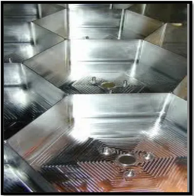
2 Figure 1.1: Aerospace monolithic component. Retrieved from http://www.autindustries.com
Tongyue et al. (2010) demonstrated, deformation is occur in the machining of thin-wall part which resulting a dimensional surface error, due to the poor stiffness of thin-wall feature. The dimensional surface error is caused generally by the deflection of the thin-wall workpiece and the end mill tool during milling, which results in variation of the tool radius immersion.
According to Izamshah et al. (2013), end mill geometrical features effect on the cutting performance such as the cutting forces, quality of machined surfaces, shape accuracy, cutting edge wear and tool life. Peterka et al. (2010) have added that the deflection and chatter vibration of the workpiece in milling a thin-walled structure is due to low stiffness, had a negative effect on the geometric accuracy and surface integrity. Therefore, it is necessary to select optimal cutter features when considering those effects. The geometrical feature of end mills includes the helix angle, number of flutes, rake angle and clearance angle. Each of the geometric features has their own specific function and need to be modelled and simulate using the finite element analysis method to effectively predict the machining surface errors.
3 performance based on the cutter helix angle and number of flutes when milling of thin-wall component.
1.2 Problem Statement/ Current Technique in Machining Thin-Wall
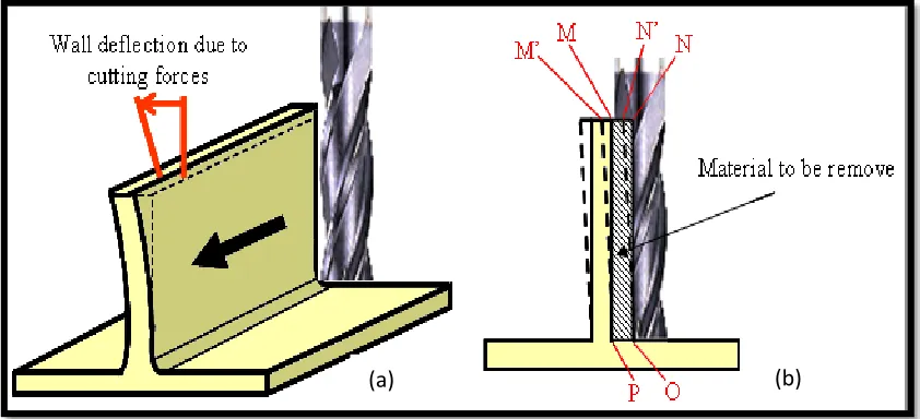
[image:18.612.116.537.407.599.2]Manufacturer poses a great challenge especially on machining aerospace component that contains a thin-wall feature due to the tight dimensional tolerance. One of the challenges faced is the dimensional errors caused by the cutting forces. The machining force caused the part deflection to deflect and away from the cutting tool. Figure 1.2 shows the surface dimensional errors produce in machining thin-wall feature. Material in the shaded areas MNOP as depicted in Figure 1.2 (b) is to be removed. However, due to the milling force the wall is deflected which make point M moves to point M′ as well as point N to point N′. As a result, only material MN′OP is removed and produce dimensional surface errors in NON’ areas. (Panadian P, 2013)
Figure 1.2: Dimensional surface errors produce in machining thin-wall feature
(a) Deflection of the wall resulting from cutting force (b) Machining sketch of thin-wall component
Tool geometrical feature has a direct influence on the cutting performances. Each of the geometric feature has their own specific function and need to be investigate. However, the
4 conventional trial and error approach to investigate the effects of cutter geometrical feature on part deflection are often very costly, labour intensive and time consuming.
In addition, most of the related work on predicting surface error are concentrated on machining parameter and the chatter vibration of the workpiece. To the best of author knowledge, none of the past research work, study the effect of cutter geometrical feature on surface error. Thus the proposed research will benefit in providing new scientific knowledge on optimizing the tool geometric design for machining thin-wall component.
1.3 Objectives
Based on the difficulty and the time-consuming analysis process for machining thin-wall monolithic component initiated this project. Driven by the need to constantly increase the machining efficiency and part accuracy, the objectives of this project are to:
1. Modelling the effect of cutter geometrical feature (helix angle and number of flutes) for shoulder milling on surface error.
2. Validate the simulation model with experiment for an identical set of test components.
3. Once the model is validate, a set of database will be generate to analyse the effect of cutter geometrical feature namely helix angle and number of flutes on part deflection using statistical analysis.
5
1.4 Scope of Project
6
CHAPTER 2
LITERATURE REVIEW
2.1 Introduction
In this chapter, all related topics on modelling and milling of thin-wall are reviewed. This chapter will discuss mainly about cutting tool used for machining thin wall part. Apart from that, reviews on related work in machining thin-wall component also been discussed. Finally, finite element analysis is also included in this chapter for the purpose of discussing on prediction occurs during simulation of the thin wall part. The purpose of studying these topics is to collect a theoretical based for this project.
In the literatures, it shows that most of the research works done only focusing on the prediction of surface error and process planning which are difficult to control and expensive. None of the researcher investigated the effect of cutter geometrical feature on part failure for machining thin deflecting wall aerospace component.
2.2 Thin Wall Machining
7 Peterka et al. (2010) have added that thin-wall can be explained as a workpiece containing of very thin plates. Thin plate shall be deformed even a minimum cutting force acting on the surface resulted the local thickness in critical place is different. In a simple words, thin-wall component contains of walls, which is small thickness compared with other dimensions such as wall length and wall height.
According to Godoy (1996) thin-walled structures are used as structures or structural components in many engineering applications, including civil, naval, aeronautical, mechanical, chemical, and nuclear engineering. In aeronautical engineering, thin-walled is a monolithic structural component consists of several thin-wall rib and flange sections that need to be machined.
Pandian P et al. (2013) found a new approach to that to machine thin-wall component, which is use high speed machining, but it needs a high speed-milling machine. Because of that factor, high speed machining technique has been adopted for machining thin ribs. High Speed Machining (HSM) is machining of materials with 4 to 6 times the cutting speed used in conventional machining.
Apart from that, Grzesik (2008) has stated that HSM allowing machining of thin-walled parts with relatively high precision and can reduce cutting forces and heat transfer into the workpiece. Currently, the HSM of monolithic component is widely used in the aerospace industry, replacing assembled sheet metal components.
2.2.1 Shoulder Milling
8 consider the operational requirements carefully before make an optimal choice. (Mills & Persson, 2013)
According to Smith (2008), in combination of face milling with peripheral milling to produce shoulder milling, face milling is operation combined cutting action by the inserts, in the main on the tool’s periphery and, to a lesser extent by insert edges on the cutter’s face. In face milling, the cutter rotates at 90° to that of the direction of radial feed against the workpiece.
Apart from that, Smith (2008) posited that peripheral milling utilises peripherally with cutting edges that are situated in a milling cutter body which is horizontally spindle mounted. The cutter rotates around a horizontal axis, this axis being parallel to the tangential feeding direction. Peripheral milling has a depth of cut in a radial direction that will determine how deep the cutter diameter will penetrate into the workpiece. There are two peripheral milling strategies that can be used with these horizontally-mounted cutters, these are either ‘Up-cut’, or ‘Down-cut’ milling operations. This project only focus on ‘up-cut’ milling operations.
2.2.2 Milling Thin-Walls
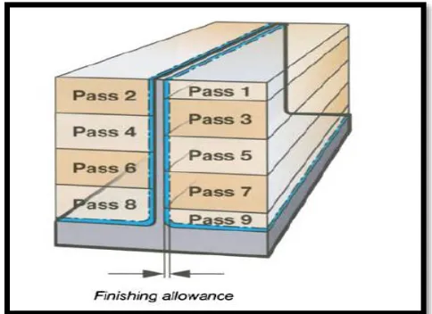
9 a) ‘Waterline milling’(Figure 2.1) – this is where either side of the thin-wall feature is milled
[image:24.612.204.450.134.312.2]to set depths, in non-overlapping passes. (Smith, 2008)
Figure 2.1: Waterline milling (Smith, 2008)
b) ‘Step-support milling’ (Figure 2.2) – this technique utilizes a similar approach to the previous method, but in this case, there is an overlap between passes on opposite sides of the wall. This strategy gives more support at the vicinity where machining occurs and the cutting forces are less likely to distort the wall as its height increases. (Smith, 2008)
[image:24.612.204.446.456.632.2]