Theses
Thesis/Dissertation Collections
5-1-1979
An electronic switching system: a computer model
for traffic study
Richard McInnes
Follow this and additional works at:
http://scholarworks.rit.edu/theses
This Thesis is brought to you for free and open access by the Thesis/Dissertation Collections at RIT Scholar Works. It has been accepted for inclusion
in Theses by an authorized administrator of RIT Scholar Works. For more information, please contact
.
Recommended Citation
A COMPUTER MODEL FOR TRAFFIC STUDY
by
Richard D. McInnes
A Thesis Submitted
in
Partial Fulfillment
of the
Requirements for the Degree of
MASTER OF SCIENCE
in
Electrical Engineering
Approved by:
Prof.
Prof.
Prof.
George A. Brown
(Thesis Advisor)
Name Illegible
Harvey E. Rhody
(Department Head)
DEPARTMENT OF ELECTRICAL ENGINEERING
COLLEGE OF ENGINEERING
ROCHESTER INSTITUTE OF TECHNOLOGY
ROCHESTER, NEW YORK
I
wouldlike
to
thank
Professor
George
A.
Brown
for
his
guidance andencouragement,
Ms.
Paula
Victor
for
her
long
hours
oftyping,
andmy
wife,
Barbara,
for
her
patience and understanding.-x-When
designing
atelephone
switching
system,
it
is
necessary
to
ensurethat
the
system willbe
ableto
handle
a prescribedquantity
oftraffic
(telephone
calls)
;
both
atany
particularinstant
andduring
agiven period of
time.
By
modelling
the
switching
system with a
digital
computer,
it
is
possibleto
determine
the
traffic
handling
capability
ofthe
system prior
to
investing
in
a prototype.In
this
manner,
the
system architecture canbe
alteredby
merely
changing
software ratherthan
by
rearranging
the
hardware
in
a prototype.The
savingsin
terms
of
time
andmoney
providethe
stimulusfor
taking
this
type
of approach.-11-Page
Acknowledgments
'.i
Abstract
ii
List
ofTables
iv
List
ofFigures
vI
.Introduction
2
II
.Call
Switching
Matrix
6
III.
Path
Search
Algorithm
10
IV.
Program
Operation
13
V.
Program
Utilization
33
VI
.Summary
3
9
Bibliography
4 0
-in-Page
Table
1:
Sample
Statistics
for
100
Call
Attempts
35
-iv-Page
Figure
1:
A
Six-by-six
Crosspoint
Switch
2
Figure
2:
A
4096
x4096
Matrix
3
Figure
3
:Schematic
Representation
of aThree
Stage
Matrix
5
Figure
4
:Schematic
Representation
of aFolded
Three
Stage
Matrix
5
Figure
5
:One
Grid
Layout
7
Figure
6:
Three
Stage
Matrix
(Shown
Schematically)
Showing
Redundant
Paths
9
Figure
7
:Matrix
Simulation
Program
Flowchart
13
[image:7.569.82.425.273.504.2]-v-I
.INTRODUCTION
The
programdescribed
in
this
paper simulatesthe
callswitching
matrixin
a4 096
line
telephone
central
office.
Any
ofthe
4096
lines
canbe
connectedto
any
otherline
with a maximum of128
connections atany
giventime.
The
matrix consists ofindividual
solid state switches called crosspoints which can
be
closed
to
complete
an electrical circuit.These
crosspoints
are arrangedin
a grid as shownin Figure
1.
Crosspoint
B
Inlets
C
v
ct r/
j
\4
r
> c>
ct c
, r
('
li
3 '1
'
S
c i n > t7
> (>
1
l
c
L
(
J
ci cI <.
>-
it i
C
f
'< 1 <i
t
Outlets
o =
Open
Crosspoint
Q
=Closed
Crosspoint
Figure
1
The
six-by-six crosspointin
Fig.
1
has
36
individual
crosspoints.Of
these
36
crosspoints,
33
are open and
three
are closed.In
this
case,
the
closed crosspoints are
designated
(B,5)
,(D,4)
,and(E,l)
and
connect
inlets
B,D,
andE
to
outlets5,4,
and1
respectively.
Any
inlet
canbe
connectedto
any
outlet.The
matrixis
abidirectional
device.
The
inlets
couldhave
been
1
to
6
andthe
outletsA
to
F;
it does
notmatter.
It
is
the
conceptthat
is
important.
It
would seemthat,
if
this
system would workfor
a single six-by-sixmatrix,
it
would also workfor
a
4096
by
4096
matrix.Each
line
wouldhave
two
appearances one as an
inlet
and one as an outlet asshown
in
Figure
2.
As
an addedbenefit,
this
systemwould permit a maximum of
4096/2
or2048
simultaneousconnections.
Everyone
couldbe
using
the
phone atthe
same
time!
1
>-2
>-Inlets
3
>-4095
V
4096
>-1
3
...Outlets
v
4095
4096
Figure
2
At
first
glance,
this
system seemsideal.
However,
this
is
notthe
case.To
implement
such asystem would require a
4
096-by-4096
matrix.This
matrix would
have
4096
x4096
or16,777,216
crosspoints.The
size and cost wouldbe
prohibitive.The
possibility
of crosspoint
failure
leads
to
anotherdrawback.
If,
for
example,
the
(1,3)
crosspoint wereto
fail,
1
couldnot call
3.
This
makes100
per centreliability
arequirement of
the
system.Such
reliability
is
notavailable at
any
price.It
is
obviously
notnecessary
for
100
per centof
the
telephones
to
be
in
use atany
onetime.
Normally,
less
than
20
per cent arein
use atany
onetime.
If
50
phones arein
use,
there
are50/2
or25
connections.This
indicates
that
there
needbe
only
half
asmany
pathsor ways
to
getthrough
the
switching
matrix asthere
aretelephones
in
use.By
using
a multistagematrix,
it
is
possibleto
decrease
the
cost ofthe
connection matrixby
using
fewer
crosspoints and atthe
sametime
improve
its
reliability.
A
three
stage matrixis
shownschematically
Inlets
Outlets
[image:11.569.78.501.103.728.2]Figure
3
Schematic
Representation of aThree
Stage
Matrix
All
ofthe
inlets
are atthe
left
side ofthe
diagram
and all of
the
outlets are atthe
right.A
pathfrom
an
inlet
to
an outlet starts atthe
left
andtraces
from
left
to
rightthrough
the
A,B,
andC
stages.It
must
be
pointed outthat
a pathdoes
notactually
existin
the
matrix untilthe
appropriate crosspoints are closed.A
telephone
mustbe
ableto
both
make(originate)
a call and receive
(terminate)
acall;
therefore,
eachline
musthave
two
appearances one as aninlet
and oneas an outlet.
This
leads
to
the
concept ofthe
folded
matrix shown
schematically
in
Figure
4.
The
set ofinlets
is
identical
withthe
set of outlets.These
appearancesare called ports.
a . ... \
A
B
C
Ports
I
\
7
Figure
4
Schematic
Representation
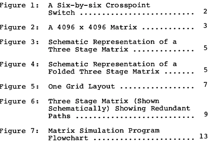
ofII.
CALL
SWITCHING
MATRIX
The
A
stage ofthe
three
stage matrixfor
which
the
programin
this
paper was written consistsof
128
A
switches,
each with32
inlets
andfour
(4)
outlets.
The
B
stagehas
64
B
switches,
each witheight
(8)
inlets
andfour
(4)
outlets;
andthe
C
stage made
up
of256
C
switches,
each with16
inlets
and
16
outlets.Each
group
of eightA
switches andfour
B
switches comprise aGrid.
There
are16
Grids
in
a4096
line
switching
system.One
Grid
andits
connections
to
the
C
stage are shownin
Figure
5
onthe
following
page.The
B
andC
stages are connectedin
the
samefashion
asthe
A
andB
stages.The
portsare numbered
from
0
to
31
to
facilitate
their
representation
in
binary.
The
inlets
in
each switch are referredto
ascolumns and
the
outlets as rows.The
outlets of anA
switch are
A
rows andthe
inlets
of aB
switch areB
columns.
Note
in
Figure
5
that
row3
from
A
stage,
switch
0
goesto
B
stage,
column0
onB
switch3.
(Recall
that
anA
switchhas
four
rows oroutlets.)
The
matrixis
designed
sothat
the
A
row numberis
alwaysthe
same asthe
B
switch number andthe
A
switch numberis
alwaysthe
sameas
the
B
column number.This
greatly
simplifiesthe
task
ofA STAGE
B STAGE
Inlet
Column
#
Cutlet
Row
#
31
0
31
0
31
0
31
0
31
0
31
0
31'
-I
:
i
2
3
4
-->
4
*|_
i"^"
5
6
Inlet
Column
#
Outlet
Row
#
Figure
5
[image:13.569.72.501.113.646.2]The
three
stage matrix system makesit
possible
to
construct
the
pathsin
steps ratherthan
all at once as
in
the
matrix picturedin
Figure
2.
Six
steps are requiredin
athree
stage system-three
to
getfrom left
to
right andthree
moreto
get
back
from
rightto
left.
The
sixstep
pathconstruction provides great
flexibility
because
there
aremany
possible variations of each step.This
flexibility
allowsthe
smallthree
stagematrix
to
do
the
work of a muchlarger
one stagematrix.
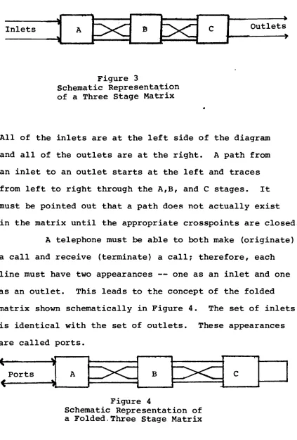
Reliability
ofthe
matrixis
greatly
increased
because
it
is
possibleto
connectany
two
ports with severaldifferent
paths as shownin
Figure
6
onthe
following
page.Thus,
if
acrosspoint which
forms
part of one pathfails,
A
STAGE
B
STAGE
C
STAGE
Orig
inating
0
31
*
Termin
ating
0
0
0
0
0
Figure
6
Three
Stage
Matrix
(Shown
Partially)
[image:15.569.83.512.95.706.2]III.
PATH
SEARCH
ALGORITHM
The
path searchbegins
withthe
loading
ofthe
originating
andterminating
equipment numbersinto
the
path search register.The
originating
grid,
originating
A
stage switch andA
row zero are compared withthe
contents ofthe
call store memory.If
there
is
amatch,
it
meansthat
zerois
busy
andA
row oneis
then
tried
in
the
same manner.If
A
row onei%
busy,
A
rowtwo
is
tried
andthen,
if
necessary,
A
rowthree
is
tried.
The
callis
blocked
if
A
rowthree
is
busy.
When
afree
A
rowis
found,
the
B
stage switchis
known.
(A
row equalsB
stageswitch.)
The
B
rowis
found
by
comparing
the
originating
grid,
originating
A
switch,
andB
row zeroto
the
contents ofthe
call store.If
B
row zerois
busy,
oneis
addedto
the
B
row andthe
new
B
rowis
tested
for
busy.
If
B
row3
is
busy,
oneis
added
to
the
A
row andthe
tests
are repeated.When
afree
B
rowis
found,
the
C
stage switchis
known.
(B
row equalsC
stageswitch.)
The
C
rowis
found
by
comparing
the
originating
grid,
originating
A
switch,
originating
A
row,
originating
B
row,
andC
row zeroto
the
contents of
the
call store.If
the
C
rowis
busy,
oneis
added
to
it
and a newtest
is
made.If
C
row15
is
busy,
one
is
addedto
the
B
row and newtests
are made onthe
B
row and
then
onthe
C
rows again until afree
C
rowis
found.
terminating
half
ofthe
pathbecause
the
multistage matrixis
designed
sothat
there
is
only
oneway
to
getto
any
given
terminating
equipment numberfrom
any
givenoriginating
C
column.The
terminating
C
row equalsthe
originating
C
switch and
the
terminating
C
switch equalsthe
originating
C
row except whenthe
originating
C
row equalsthe
originating
C
switch.Then
the
terminating
C
switch equalsthe
terminating
C
row.The
terminating
C
switch equalsthe
originating
C
switch plus one whenthe
originating
C
switchis
even orit
equalsthe
originating
C
switch minus one whenthe
originating
C
switchis
odd.Path
Search
Sequence
1.
Find
originating
A
row(0-3)
Then
originating
B
switch =originating
A
row.2.
Find
originating
B
row(0-3)
Then
originating
C
switch =originating
B
row.3.
Find
originating
C
row(0
-15)
Then
terminating
C
switch =originating
C
rowAnd
terminating
C
row =originating
C
switch(if
originating
C
roworiginating
C
switch)
OR
terminating
C
row =terminating
C
switchAnd
terminating
C
switch =originating
C
switch+
1
(if
originating
C
switchis
even)
OR
terminating
C
switch =originating
C
switch -1
(if
originating
C
switchis
odd)
known.
Now
allthat
remainsis
to
checkfor
busy
onseveral parts of
the
terminating
path.The
path searchchecks
for
busy
onthe
terminating
B
row.If
the
terminating
B
rowis
busy,
oneis
addedto
the
C
row andthe
appropriatebusy
tests
arethen
made.The
terminating
A
rowis
checkedfor
busy
in
anidentical
manner.
One
last
busy
checkis
required.*If
the
originating
andterminating
lines
are onthe
sameA
switch,
they
mightbe
connectedto
the
sameA
row atthis
stage of
the
path search algorithm.The
originating
andterminating
grids,
A
switches andA
rows are compared.If
they
areequal,
oneis
addedto
the
originating
C
row and newbusy
tests
are made.This
concludesthe
path search.Calls
canbe
blocked
in
three
ways.The
first
occurs when
the
terminating
numberalready
has
acall,
i.e.
it
is
busy.
The
second occurs whenthe
matrixcontains calls whose paths
block
all possible pathsbetween
the
neworiginating
andterminating
numbers.This
callis
referred
to
asbeing
blocked.
The
third
way
a call canbe
blocked
occurs whenthe
new callis
the
12
9th
callin
the
matrix simultaneously.
The
callprocessing
circuitry
in
the
matrix
is
designed
to
hold
a maximum of128
callssimultaneously
due
to
memory
constraints.Thus,
the
129th
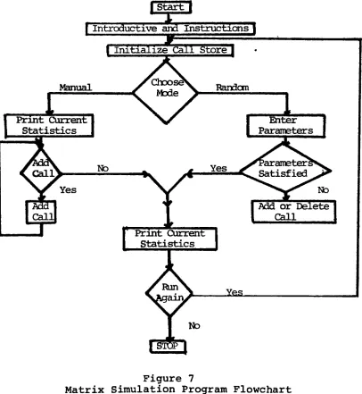
The
operation
ofthe
Matrix
Simulation Program
is
illustrated
in
Figure
7
below.
I
Start
1
.
1
,
[
Introductive
andInstructions
|
\
Call
Store
|
I"^i
-S
I
Manual
Current
Statistics
Yes
No
Randcm
1
Enter
Parameters
Md
orDelete
Call
J&s-Figure
7
[image:19.569.84.490.202.643.2]Introduction:
Lines
10
-190:
The
beginning
ofthe
program containsthe
necessary
declaration
statements and provides anexplanation of
its
use.Descriptions
ofthe
two
modes,
manual and
random,
are printed.Lines
200
-220:
This
is
followed
by
initialization
ofthe
Call
Store
(M)
memory
matrix andsetting
the
number of callsin
the
matrix(N)
to
zero.Lines
230
-330:
The
operatoris
next askedto
choosethe
mode ofcall programming.
He
respondsby
assigning
a valueto
a mode select variable
(Q0$)
whichis
then
tested
andthe
program
branches
to
the
desired mode,
manual or randomsimulation,
orto
the
conclusion ofthe
simulation.Manual
Mode
:Lines
340
-390:
In
the
manualmode,
the
memory
timeslot
(T)
,number of calls attempted
(Al)
, number of callsbusy
(Bl)
,The
operatoris
told
how many
calls arecurrently
in
the
matrix(N)
andis
askedto
assign a variable(Ql$)
expressing
his
desire
to
add another call orfinish
the
simulation.
This
variable(Ql$)
is
tested
andthe
programbranches
to
the
appropriatelocation.
Lines
480
-620:
The
operatoris
askedto
type
in
the
Originating
Equipment
Number
(Nl)
whichis
then
broken
down
into
Originating
Grid
(A)
,Originating
A
switch(B)
, andOriginating
A
column(C)
.Lines
630
-690:
The
Call
Store
memory
matrix(M)
is
searchedto
determine
whetherthe
Originating
Equipment Number
(Nl)
is
busy
oridle.
Lines
700
-770:
If
it
is
busy,
the
operatoris
informed
and askedto
assign a variable(H0$)
whose valuedepends
on whetherhe
wantsto
terminate
the
call or continue.The
programthen
branches
to
the
appropriatelocation.
Lines
78
0
-810:
(M(13,WD)
is
setto
zero,
the
number of callsin
the
matrix(N)
is
decremented,
and controljumps
to
line
480.
Lines
820
-990:
The
program asksfor
the
Terminating
Equipment
Number
(N2)
.It
is
comparedto
the
Originating
Equipment
Number
(Nl)
and,
if
they
areequal,
the
busy
call counter(Bl)
and attempted call counter(Al)
areincremented.
The
operator
is
informed
that
the
originating
equipment number(Nl)
is
equalto
the
terminating
equipment number(N2)
.Control
then
passesto
line
48 0.
Lines
1000
-1030:
If
the
Originating
Equipment
Number
(Nl)
is
notequal
to
the
Terminating
Equipment
Number
(N2)
,the
Terminating
Equipment
Number
(N2)
is
broken down
into
Terminating
Grid
(J)
,Terminating
A
switch(K)
, andTerminating
A
Column
(L)
.Lines
1040
-1090:
The
program searchesthe
Call
Store
memory
matrix
(M)
to
determine
whetherthe
Terminating
Equipment
Number
(N2)
is
idle
orbusy.
Lines
1100
-1210:
busy
(Al)
areincremented.
The
operatoris
told
that
the
equipment number
is
busy
andis
askedto
assign a variable(Hl$)
telling
whetherhe
wantsto
terminate
the
call orcontinue.
If
it
is
idle,
control passesto
line
1260.
Lines
1220
-1250:
If
the
callis
to
be
terminated,
theidle-busy
git
(M(13,XD)
is
setto
zero andthe
number of callsin
the
matrix(N)
is
decremented.
Control
then
jumps
to
line
43
0.
If
the
callis
notto
be
terminated,
controljumps
directly
to
line
48 0.
Lines
1260
-1320:
The
calls attempted counter(Al)
andtimeslot
(T)
areincremented.
If
the
timeslot
(T)
is
less
than
129,
controljumps
to
line
2130;
otherwise,
128
is
subtracted
from
the
timeslot
(T)
andit
is
tested
againuntil
it
is
less
than
129.
Random
Mode:
Lines
1330
-1400:
In
the
Random
Mode,
the
operatoris
askedto
enter
the
number of callsto
be
attempted(Al)
andthe
Lines
1410
-1470:
The
calls attempted(Al)
, callsbusy
(Bl)
,calls
blocked
(Kl)
, and alltimeslots
full
(Fl)
countersare
initialized
at zero andthe
always add callflag
(A3)
is
setto
one.If
the
value ofthe
calls attempted counter(Al)
is
greaterthan
or equalto
the
number of callsto
be
attempted(El)
, controljumps
to
line
2960.
Lines
1480
-1500:
If
the
number of callsin
the
matrix(N)
is
less
than
the
average number of callsto
be
in
the
matrix(E2)
, controljumps
around a statement which setsthe
always add
flag
(A3)
to
zero.Then,
if
the
flag
(A3)
is
equal
to
one,
controljumps
to
line
1710
where a callis
attempted.
Lines
1510
-1570:
A
variable(A4)
takes
on a random valuebetween
zero and
one;
exclusive ofboth.
If
that
variable(A4)
is
less
than
0.5,
controljumps
to
line
1560
wherethe
programtests
to
seeif
there
areany
callsin
the
matrix.If
there
are no
calls,
controljumps
to
line
1710
to
add a call.If
there
is
acall,
it
is
deleted
in
the
nextblock
ofthe
program.
If
the
variable(A4)
is
greaterthan
0.5,
control(when
A4
=0.5),
controljumps
back
to
line
1510
and anew random value
is
assigned.Lines
1580
-1700:
The
callsin
matrix counter(N)
is
decremented
and
the
delete
timeslot
counter(Vl)
is
initialized
to
zero.
The
delete
timeslot
(V)
takes
on a randominteger
value
between
one and128,
inclusive.
Then
the
delete
timeslot
counter(Vl)
is
incremented
andtested.
If
it
(VI)
is
greaterthan
128,
controljumps
to
line
1470.
Otherwise,
the
idle-busy flag
(M(13,V)
is
tested
for
busy
condition-that
is
equalto
one.If
it
(M(13,V)
is
equalto
one,
controljumps
to
line
1690
wherethe
flag
(M(13,V)
is
setto
zero;
then
back
to
line
1510.
If
the
flag
(M(13,V)
is
equalto
zero-idle
condition,
the
delete
timeslot
(V)
is
incremented.
If
the
timeslot
(V)
is
less
than
129,
controljumps
back
to
line
1620;
otherwise,
128
is
subtractedfrom
(V)
andthen
controljumps
back
to
line
162
0.
Lines
1710
-1860:
The
calls attempted counter(Al)
is
incremented
and
the
addtimeslot
counter(Ul)
is
initialized
to
zero.The
addtimeslot
(U)
takes
on a randominteger
valuebetween
is
incremented
andtested.
If
it
(Ul)
is
less
than
orequal
to
128,
controljumps
to
line
1810
wherethe
idle-busy
flag
(M(13,U)
is
tested
for
idle
condition-that
is
equal
to
zero.If
the
flag
(M(13,U)
is
equalto
zero,
control
jumps
to
line
1860
wherethe
value ofthe
addtimeslot
(U)
is
assignedto
the
path searchtimeslot
(T)
.Otherwise,
the
addtimeslot
(U)
is
incremented
andtested
to
determine
if
it
is
less
than
129.
If
so,
controljumps
back
to
line
17 60
wherethe
addtimeslot
counter(Ul)
is
incremented.
If
the
addtimeslot
(U)
is
notless
than
129,
then
129
is
subtracted andit
is
tested
again.If
the
addtimeslot
counter(Ul)
is
greaterthan
128,
the
number oftimes
alltimeslots
arefull
counter(Fl)
is
incremented
and control
jumps
back
to
line
156
0.
Lines
1870
-1960:
A
randominteger
valuebetween
one and4
096,
inclusive
is
assignedto
the
originating
equipment number(Nl)
.The
originating
equipment number(Nl)
is
then
broken
down
into
originating
grid(A)
,originating
A
switch(B)
,and
originating
A
column(C)
.The
originating
equipmentnumber
(Nl)
is
comparedto
all equipment numbersin
the
matrix.
If
it
(Nl)
is
busy,
controljumps
back
to
line
1870
and a neworiginating
equipment number(Nl)
is
chosen.The
terminating
equipment number(N2)
takes
on an
integer
valuebetween
one and4096,
inclusive.
It
(N2)
is
tested
to
determine
if
it
is
equalto
the
originating
equipment number(Nl)
.If
they
areequal,
anew
terminating
equipment number(N2)
is
chosen andthe
test
is
repeated.Next
the
terminating
equipment number(N2)
is
comparedto
all equipment numbers*in
the
matrix.If
the
terminating
equipment number(N2)
is
busy,
the
busy
counter(Bl)
andthe
number of calls attempted counter(Al)
controljumps
back
to
line
147 0.
Path
Search:
Lines
2130
-2300:
The
originating
A
row(D)
is
initialized
atminus one and
then
incremented.
It
(D)
is
tested
andif
it
is
greaterthan
three,
controljumps
to
line
2190
wherethe
callsblocked
counter(Kl)
is
incremented.
Next,
the
value of
the
mode select variable(Q0$)
is
tested
to
determine
whetherthe
programis
being
runin
the
Manual
or
Random
mode and controljumps
back
to
the
beginning
ofthe
appropriateblock
of code.If
the
callis
notblocked,
control
jumps
to
line
2260.
Then
the
originating
grid(A)
of
the
matrixto
determine
if
the
(D)
is
busy
-equal
to
one.
If
the
originating
A
row(D)
is
busy,
controljumps
back
to
line
2150
whereit
(D)
is
incremented
andtested
again,
first
for
being
greaterthan
three
andthen
for
being
busy.
If
the
originating
A
row(D)
is
notbusy,
control passes
to
the
next section ofthe
program.Lines
2310
-2400:
The
originating
B
row(E)
is
initialized
atminus one and
then
incremented
andtested.
If
it
(E)
is
greater
than
three,
controljumps
back
to
line
2150
wherethe
originating
grid(A)
,originating
A
switch(B)
,originating
A
row andthe
originating
B
row(E)
are comparedto
the
contents ofthe
matrixto
determine
if
the
originating
B
row(E)
is
busy
-equal
to
one.If
the
originating
B
row(E)
is
busy,
controljumps
back
to
line
2330
whereit
(E)
is
incremented
andthe
tests
arethen
repeated.
If
the
originating
B
row(E)
is
notbusy,
controlpasses
to
the
next section ofthe
program.Lines
2410
-2500:
The
originating
C
row(F)
is
initialized
at minusone and
then
incremented
andtested
to
determine
if
it
(F)
is
greaterthan
15.
If
the
originating
C
row(F)
is
greateroriginating
originating
grid(A)
,originating
A
row(D)
andoriginating
C
row(F)
are comparedto
the
contents ofthe
matrix
to
determine
if
the
originating
C
row(F)
is
busy
-equal
to
one.If
the
originating
C
row(F)
is
busy,
controljumps
back
to
line
2430
wherethe
originating
C
row(F)
is
incremented
andthe
tests
arerepeated.
Lines
2510
-2640:
The
originating
C
switch(03)
is
computed.If
the
originating
C
row(F)
equalsthe
originating
C
switch(03)
, controljumps
to
line
257
0
and a variable(0)
takes
on
the
integer
value ofhalf
the
value ofthe
originating
C
switch(03)
.This
is
usedto
determine
whetherthe
originating
C
switch(03)
is
even or odd.If
it
(03)
is
even,
the
terminating
C
switch(T3)
is
equalto
the
originating
C
switch(03)
plus one andif
it
(03)
is
odd,
the
terminating
C
switch(T3)
is
equalto
the
originating
C
switch minus one.In
eithercase,
the
terminating
C
row(T)
is
equalto
the
terminating
C
switch(T3)
.If
the
originating
C
row(F)
is
not equalto
the
originating
C
switch
(03)
,the
terminating
C
row(F)
is
set equalto
the
originating
C
switch(03)
andthe
terminating
C
switch(T3)
Lines
2650
-2720:
The
terminating
A
row(G)
andterminating
B
row(H)
are computed and compared withthe
contents ofthe
matrix
to
determine
whetherthey
arefree
orbusy.
If
either
the
terminating
A
row(G)
orterminating
B
row(H)
is
busy,
controljumps
back
to
line
2430
wherethe
originating
C
row(F)
is
incremented.
Lines
2730
-2970:
The
originating
grid(A)
,originating
A
switch(B)
,originating
A
column(C)
,originating
A
row(D)
,originating
B
row(E)
,originating
C
row(F)
,terminating
A
row(G)
,terminating
B
row(H)
,terminating
C
row(F)
,terminating
grid(J)
,terminating
A
switch(K)
, andterminating
A
column(L)
are all storedin
the
matrixand
the
idle-busy flag
(M(13,T)
is
set equalto
one.The
value ofthe
mode select variable(Q0$)
is
tested
andif
the
programis
running
in
the
manualmode,
the
number ofcalls
in
the
matrix counter(N)
is
tested
andif
it
is
less
than
128,
it
is
incremented.
Then
controljumps
back
to
the
beginning
ofthe
manual section ofthe
program.If
the
program
is
in
the
randommode,
the
number of callsin
the
matrix counter
(N)
is
incremented
and controljumps
back
to
Lines
2980
-3110:
The
number of calls attempted(Al)
,the
number of calls
encountering
busy
(Bl)
, andthe
numberof calls
blocked
(Kl)
are printed out.Then
if
the
program
is
in
the
manualmode,
controljumps
back
to
line
180.
Otherwise,
the
number of callsblocked
due
to
all128
timeslots
being
full
(F)
is
printed out andthen
controljumps
to
line
210.
This
is
followed
by
Variable
Descriptions
M
Call
storememory
matrixN
Number
of callsin
the
matrixQ0$
Mode
selectT
Timeslot
Al
Number
of calls attemptedBl
Number
of callsencountering
busy
Kl
Number
of callsblocked
-01$
Manual
add questionNl
Originating
equipment numberA
Originating
Grid
B
Originating
A
Switch
C
Originating
A
Column
W
Iterative
manualoriginating
busy
counterWl
Save
iterative
manualoriginating
busy
counterH0$
Originating hang-up
or continueN2
Terminating
equipment numberJ
Terminating
gridK
Terminating
A
switchL
Terminating
A
columnX
Iterative
manualterminating
busy
counterXl
Save
iterative
manualterminating
busy
counterHl$
Terminating
hang-up
or continueEl
Enter
number of callsto
be
attemptedE2
Average
number of callsA3
Always
add a callFl
Number
oftimes
alltimeslots
arefull
A4
Add
ordelete
VI
Delete
timeslot
counterV
Delete
timeslot
Ul
Add
timeslot
counterVariable
Descriptions
(Cont'd.)
Y
Iterative
randomoriginating
busy
counterZ
Iterative
randomterminating
busy
counterD
Originating
A
rowP
Timeslot
counter1
E
Originating
B
rowQ
Timeslot
counter2
F
Originating
C
rowR
Timeslot
counter3
03
Originating
C
switchI
Terminating
C
rowT3
Terminating
C
switch0
Originating
C
switch evenMATRIX
10 REM MATRIX SIMULATOR
20
REM30 REM WRITTEN BV RICHARO
D.
MCINNESao REM
50
B9=BRK(0)
60 DIM
Mri3.129)
,Q0$t255) ,3 1t?551
,HOSt?551,HI SI255J
70 REM INTRODUCTION
BO PRINT
90 PRINT
"THIS
PROGRAMSIMJLiATES
THE
CALL
SWITCHING
MATRIX IN A 4096 LINE"100 PRINT
"CENTRAL
OFFICE FORTRAFFIC
STUDYPURPOSES.
THE LINES ARE NUMBERED"110 PRINT "FROM 0 TO
4095.
THE
MATRIX CAY HOLD A MAXIMUM OF 128 CALLS AT ANY"120
PRINT "GIVENTIME.
THESE
CALLS CANBE
PROGRAMMED MANUALLY OR SELECTED AT" 130 PRINT "RANDOM BYTHE
COMPJTER.
IFTHE
CALLS ARE PROGRAMMED MANUALLY ONLY"lttO PRINT
"THE
LAST 128CALLS
HILL
BE
INTHE
MATRIX AT ANYTIME.
ALL OTHERS" 150 PRINT"WILL
BE
REMOVED.
THISMODE
IS USEFUL FOR STUDYINGTHE
BLOCKING" 160 PRINT "CHARACTERISTICS OFTHE
MATRIX.
IF THE COMPUTERIS
ASKED TO SELECT"170
PRINT "RANDOM CALLS,THOSE
CALLSWILL
BE
SET UP AND TAKEN DOWN AT RANDOM." 180 PRINT "IF THE COMPUTER ATTEMPTS TO SET JP ACALL
WHENTHERE
ARE ALREADY"190 PRINT "129 CALLS IN
HE
MATRIX,
THATCALL
WILLBE
BLOCKED."200
REM INITIALIZE CALL'STORE
MATRIX210
MAT MsZER220 N=0
230
RE** MODE SELECT240
PRINT250
PRINT "IF YOU WISHTO
ENTER THE ORIGINATING AND TERMINATING EQUIPMENT"260 PRINT "NUMBERS MANUALLY
TY'E
'MANUAL*.
IF YOU WANT THE COMPUTER TO"270 PRIMT "SELECT RANDOM E3JI'*ENT NJBERS TY^E
'RANDOM'.
IF YOU ARE"280 PRINT "FINISHED TYPE
'rINISH'.
"?
290
INPUT 10$300
IF Q0SIl,l)s"M"THEN JttO
310
IF Q0tU,U="R"THEN 1330
320 IF QO*tl,ll="F"
THEN 3090
330 GOTO 230
340
REM MANUALMODE
350 REM INITIALIZE
TIMES.
OT,ATTEMPT,
3JSY,
AND BLOCKED COUNTERS360
T=0
370 Also
380
B1=0
390 Kl=0OOO REM ADD A CALL OR
*INISH?
410 PRINT
420 PRINT "THERE ARE PRESENTLY ":Nj"
CALLS IN
THE
MATRIX.
IF YOU WISH TO ADD"430 PRINT "ANOTHER CALL
TY^E
'A^D',
OTHERWISE TYPE'FINISH'.
"440 INPUT 11$
450 IF Q1$U,1]="A" THEN
490 460 IF 31*tl,ll="F"
THEN 290
470 GOTO 400
480 REM ADD A CALL
490 REM ORIGINATING E3JI-MENT NJM3ER
(OEN)
500
PRINT510
PRINT "ENTER ORIGINATING EOJIPMENT NUMBER"
520
INPUT Nl530
IF N1-INTCN1)#0 THEN570
540
IF Nl>'i095 THEN 570550
IF N|<0 THEN 570 560 GOTO 600570
PRINT560
PRINT "EQUIPMENT NUMBERS MJSTBE
INTEGERS BETWEEN 0 AND 4095, INCLUSIVE."590
GOTO 490600 A=INT(Nl/256)
620
C=INT(N1-256*A-32*B)
630 REM
DETERMINE
WHETHER OENIS
IDLE
OR
BUSY640
FOR
W=lTO
128650 WlsW
660 IF M(l,WJ=A AND
Mt2,WJsB
AND
Mf3,wiC
ANDMtl3,W)=l
THEN 700 670 IF MtlO.WlsA ANDMtll,W]sB
ANDMtl2,W]sC
ANDMfl3,WJs|
THEN700
680NEXT
W690
GOTO
820
700
REM OEN BUSY HANG J ORCONTINUE?
710
PRINT720
PRINT"THIS
EQUIPMENT NJM3ERIS
BUSY.
IFYOU
WISHTO
TERMINATE
ITS
CALL"730
PRINT"TYPE
'HANG
U',
OTHERWISE
TYPE
'CONTINUE'.
"
740
INPUT HOI750
IF HOStl,U="C" THEN490
760
IF H0$tl,U="H"THEN
780
770
GOTO
700
760
REM HANG UP790
M[13,W1J=0
800
N=N-1
810
GOTO
480B20
REMTERMINATING
EOUI'MENT NUMBER(TEN)
B30 PRINT840
PRINT "ENTERTERMINATING
E3JIMENT NUMBER"
850 INPUT
N2
860
IF N2-INT(N2)*0 THEN900
870
IF N2>4095 THEN 900880
IF N2<0 THEN 900 890 GOTO 930900
PRINT910
PRINT "E3UIPMENTNUMBERS
MJSTBE
INTEGERS BETWEEN 0 AND 4095, INCLUSIVE."920
GOTO 920930
IFN2=N1
THEN 950940 GOTO 1000
950
B1=B1*1
960 AisAi+i 970 PRINT980
PRINT "ORIGINATINGE3JIPMENT
NUMBER = TERMINATING EQUIPMENT NUMBER"990 GOTO 490
1000 REM BREAK DOWN TEN 1010
J=INT(N?/256)
1020
K=INT((N2-256*J)/3?) 1030 L=INT(N2-256*J-32*<)1040 REM DETERMINE WHETHER TEN IS
IDLE
OR BUSY1050 FOR X=l TO 12 1060 Xl=X
1070 IF M[i,XJ=J AND M(2,X)sK AND
M[3,X1=L
AND Mtl3,Xl=l THEN 1120 1080 IF MtlO,X)sJ AND M(ll,Xls< ANDM[12,X)=L
AND M[13,X1=1 THEN 11201090 NEXT X
1100 REM TEN IS IOLE 1110 GOTO 1260
1120 REM TEN IS BUSY
1130
BlsBl+11140 AlsAl+1
1150 PRINT
1160 PRINT
"THIS
EQUIPMENT NJ9ER ISBUSY.
IF YOU WISH TOTERMINATE
ITS
CALL" 1170 PRINT"TYPE
'HANGJ",
OTHERWISE
TYE
'CONTINUE*.
"j
1180 INPUT Hl$
1190 IF Ml'l,lJsC" THEN 490 1200 IF H1$U,U="H" THEN
1220
1210
GOTO 11501220
REM HANG UP1230 Mfl3,Xll=0
1240 N=N-1 1250 GOTO 490
1260
REM INCREMENT ATTEMT COJNTER1280 REM
INCREMENT
TIMESLOT
1290
TsT*l
1300
IF T<129 THEN 21301310
T=T-129
1320
GOTO
13001330 REM RANDOM
MODE
1340 REM ENTER PARAMETERS 1350 PRINT
1360
PRINT "ENTER NUMBER OF CALLSTO
BE
ATTEMPTED"
1370 TNPUT
El
1380 PRINT
1390 PRINT "ENTER AVERAGE NJM3ER OF CALL6
TO
BE
INTHE
MATRIX '1400 INPUT
E2
1410 REM
INITIALIZE
ATTEMPT.
3JSY,
BLOCKED,
ANDFULL
COUNTERS1420 ai=o
1430 B1=0
1440 K1=0 1450 FtsO
1460 A3=l
1470 IF Al >s El THEN 2990
1490 IF
N<E2
THEN 15001490 A3=0
1500 IF A3=l THEN 1710
1510 REM AOD OR DELETE A CALL?
1520 A4=RND(t)
1530 IF A4<.5 THEN 1560
1540 IF A4>.5 THEN 1710
1550 GOTO 1510
1560 REM DELETE A
CALL
1570 IF N <s 0 THEN 1710
1590 N=N-1 1590 VlsO
1600 REM SELECT A RANDOM TIMESLOT TO
BE
DELETED1610
VsINT((129*RND(l))*n1620 V1=V1*1
1630 IF V1M28 THEN 1470
1640 IF Mtl3,Vl=l THEN 1690 1650 V=V*1
1660 IF V<129 THEN 1620
1670 VsV-129
1680 GOTO 1620
1690 MC13,V]s0
1700 GOTO 1510
1710 REM ADD A CALL
1720 AlsA1+l
1730
UlsO1740
REM SELECT A RANDOM TIMESLOT 1750 UsINT((128*RND(l))+l)1760 U1=U1*1
1770 IF Ul <= 128 THEN 1810
1780 REM
ALL
TIMESLOTS -JLL'1790 FlsFlfl
1800 GOTO 1560
1810 IF M(13,U1sO THEN I960 1820 U=U*1
1830
IF U<129 THEN 17601840 UsU-129 1850 GOTO 1760
1860 TsU
1870 REM SELECT A RANDOM OEM 1880 NlsINT(4096*PND(l))
1890 A=INT(Nl/256)
1900 B=INT((Nl-256*A)/32)
1910
C=INT(N1-256*A-32*B)1920 REM TEST OEN FOR BJSY
1940
IF MCl.YlsA ANDM[2,V1=8
ANDMt3,Yl=C
ANDMtl3,Ylsl
THEN 1870 1950 IF M[10,Y)sA ANDMfll,Y)r3
ANDMtl2,YlsC
ANDMU3,Y1=1
THEN 1870 1960 NEXT Y1970 REM SELECT A RANDOM TEN 1980
N2sINT(4096*RND(l))
1990 IF
N2=N1
THEN 19702000
J=INT(N2/256)
2010 K=INT((N2-256*J)/32)
2020
L=INT(N2-256*J-32*<)2030
REMTEST
TEN FOR 9JSY2040
FORZ=l
TO
1282050 IF Mfl.ZJrJ AND M[2,Z]=< AND
Mf3,ZJ=L
ANDMtl3,Zl=l
THEN 20902060
IF M(io,ZJ=J AND M(ll,Zls< ANDM{12,Z)=L
ANDM(i3,Z]si
THEN 2090 2070 NEXT Z2080 GOTO
2130
2090 REM TEN IS BUSY
2100
MsRl+i 2110 AlsAltl2120
GOTO 14702130
REM TEN ISIDLE
2140 Ds(-i)
2150 RFM INCREMENT AND TEST OAR
2160
0=D+1
2170 IF D>3 THEN 2190
2180
GOTO 22602190 REM
CALL
IS BLOCKED 2200 K1=K1+12210 IF QO*tl,l]="R" THEN 1470
2220
PRINT2230 PRINT
"CALL
IS BLOCKED."2240 IF QO$tl,ll="M"
THEN 400
2250 GOTO 230
2260
REM DETERMINE IF OAR TS 3JSY2270
FOR ==1 TO 1292280 IF Mll.PJsA AND M(2,3)s* AND Mf4,Pl=D AND
M[13,PJ=1
THEN 21502290 IF MtlO,?l=A AND Mtll,ls3 AND
M(7, P]=D
AND Mfi3,pjsl THEN 21502300
NEXT P2310 RFM OAR IS IDLE
2320
E=(-l)2330
REM INCREMENT AND TEST D9R2340 E=E*1
2350 IF E>3 HEN 2150
2360 REM DETERMINF. IF 03R IS 3JSY
2370 FOR
Q=l
TO 1282380
IF M[i,3l=A AND M[2,31=B AND Mfti,Q)=0 AND M[5,Q)=E AND M'13.Q1=1 THEN 23302390 IF M[10,D1=A AND M[H,31=3 AND M[7,3]=D AND Mf8,3)=E AND C13,Q1=1 THEN 2330
2400
NFXT Q2410 REM 09R IS
IDLE
2420
F=(-l)2430
REM INCREMENT AND TEST OCR 2440 F=F*12450 IF F>15 THEN 2330
2460 REM DETERMINE IF OCR IS BUSY 2470 FOR
R=l
TO 1282480 IF Mtl.RJsA AND M{2,R!=B AND M[4,R1=D AND M[5,R)=E AND Mt6.R)=F AND M[13,R1=1 THEN 2430
2490 IF MH0,R1=A AND
Mni,Rl=3
AND M(7,RJ=D AND Mf8,Rl=E AND M[9,R]=F AND M[13,RJ=1 THEN 24302500
NEXT R2510
REM OCR IS IDLE2520
D3=4*D*E2530
IF Fs03 THEN 25702540
1=03
2550 T3=F
2560 GOTO 2650
2570
0=INT(03/2)2580 IF 0=03/2 THEN 2620
2600
I=T32610
GOTO2650
2620
T3=03+l
2630
I=T3
2640 GOTO 2650
2650
G=INT(T3/4)
2660
HaT3-4*G2670 REM
DETERMINE
IF TAR AND T3R ARE BUSY2680
FOR3=1
TO 1282690 IF M[8,S1=J AND
Mf7,S)=S
AND M[8,S1=H AND MI13,S1=1 THEN 24302700
IF M110,SJ=J AND M[11,S1=< AND M[7,S1=S AND M[13,S]=1 THEN 2430 2710 NEXT S2720
IF A=J ANO B=K ANDD=5
THEN2430
2730
REM TAR AND TBR ARE' IDLE'2740 REM
STORE
PATH IN MATRIX2750 Mtl,Tl=A
2760
Mt2,T]=B 2770M(3,T1=C
2780
M[,T)=D 2790 Mr5,Tl=E 2800 M(6,T1=F 2810 Mt7,Tl=G2920
Mr8,Tl=H 2830 Mf9,Tl=I 2840 MtlO.TlsJ 2850 Mtn.TlsK 2860Mfl2,Tl=L
2870 M(13,T)=12880 IF Q0$(1,1)="M"
THEN
2910
2B90 IF Q91>
tl,
1)="R"THEN 2950
2900
GOTO 2302910 REM INCREMENT
CALL
CDJNTER2920
IF N >= 128 THEN 4102930
N=N+12940
GOTO 4002950 REM INCREMENT
CALL
COUNTER2960 N=N+1
2970 GOTO 1470
2980 REM FINISH
MANUAL
MODE
2990 PRINT
3000 PRINT "NUMBER OF CALLS ATTEMPTED "A1
3010 PRINT
3020 PRINT "NUMBER OF CALLS ENCOUNTERING BUSY ":B1
3030 PRINT
3040 PRINT "NUMBER OF CALLS 3LDC<ED
";K1
3050 IF Q0$tl,l]="M"
THEN 210
3060 PRINT
3070
PRINT "NJMBER OF CALLS BLOCKEDCALL
TIMESLOTSFULL)
";F13080
GOTO 2103090
REM FINISH3100
STOPV.
PROGRAM UTILIZATION
The
program wasdesigned
to
be
self-explanatory
in
orderto
facilitate
its
use.Rather
than
explaining
how
the
programis
used,
it
is
easier and moreinstructive
to
illustrate
its
use with several examples.Random
Mode
:The
Random
Mode
enablesthe
userto
simulatethe
actual operation of a
telephone
exchange.The
userfirst
determines
the
number of callsto
be
attempted,
thereby
setting
alimit
onthe
amount oftelephone
traffic
to
be
simulated.
The
traffic
intensity
is
determined
by
the
average number of calls
to
be
in
the
matrix.The
programselects random equipment numbers and attempts
to
setup
and
take
down
calls.A
simulation of1,000
callsis
shownIRUN MATRIX
THIS
PROGRAM SIMULATESTHE
CALL SWITCHING HATRIX INA
4096 LINE CENTRAL OFFICE FOR TRAFFIC STUDYPURPOSES.
THE LINES
ARE NUMBERED FROM0
TO
4095. THE MATRIXCAN
HOLD A MAXIMUM OF 128 CALLS AT ANY GIVENTIME.
THESE
CALL8 CAN BE PROGRAMMED
MANUALLY ORSELECTED
AT RANDOM BYTHE
COMPUTER. IF THECALLS
ARE PROGRAMMED MANUALLY ONLYTHE LAST 128
CALLS
WILL BEIN
THE MATRIX AT ANYTIME.
ALL OTHERSWILL
BE REMOVED. THIS MODEIS
USEFULPOR STUDYING
THEBLOCKING
CHARACTERISTICS
OFTHE
MATRIX.IF
THECOMPUTER
ISASKED
TO
SELECTRANDOM CALLSr THOSE
CALLS
WILLBE SET
UP AND TAKEN DOWN AT RANDOM.IF
THE COMPUTER ATTEMPTS TOSET
UPA
CALL WHENTHERE
ARE ALREADY128
CALLS INTHE
MATRIX* THATCALL WILL
BE BLOCKED.IF YOU WISH TO ENTER
THE
ORIGINATING AND TERMINATINGEQUIPMENT
NUMBERS MANUALLY
TYPE
'MANUAL'.IF
YOU WANT THE COMPUTER TO SELECT RANDOM EQUIPMENT NUMBERSTYPE
'RANDOM'. IF YOU AREFINISHED
TYPE
'FINISH'. 'RANDOMENTER NUMBER
OF
CALLS TOBE
ATTEMPTED T1000ENTER
AVERAGE
NUMBER OF CALLS TO BE IN THE HATRIX T500NUMBER OF CALLS ATTEMPTED 1000
NUMBER OF CALLS ENCOUNTERING BUSY
43
NUMBER OF CALLS BLOCKED 43
NUMBER OF CALLS BLOCKED (ALL TIMESLOTS FULL) 251
IF YOU WISH TO ENTER THE ORIGINATING AND TERMINATING EQUIPMENT
NUMBERS MANUALLY TYPE 'MANUAL'. IF YOU WANT THE COMPUTER TO
SELECT RANDOM EQUIPMENT NUMBERS TYPE 'RANDOM'. IF YOU ARE FINISHED TYPE 'FINISH'. TFINjfSH
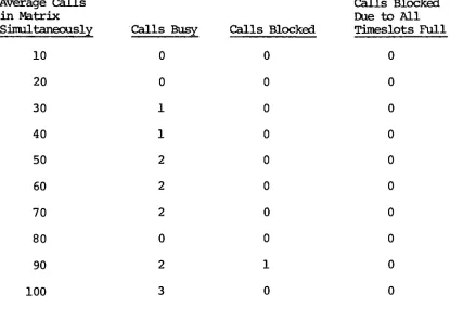
The
table
below
illustrates
the
results often
simulations
of100
random calls.In
only
one casewas a call
blocked.
No
calls wereblocked
due
to
alltimeslots
being
full.
This
is
expectedbecause
there
are
128
timeslots.
Table
1.
Sample
Statistics
for
100
Call
attempts
Average Calls
Calls
Blocked
in
Matrix
Due
to All
Simultaneously
Calls
Busy
Calls Blocked
Timeslots
Full
10
0
0
0
20
0
0
0
30
1
0
0
40
1
0
0
50
2
0
0
60
2
0
0
70
2
0
0
80
0
0
0
90
2
1
0
[image:41.569.67.482.309.604.2]Manual
Mode
:The
Manual
Mode
permitsthe
userto
setup
various call patterns and
to
study
their
effect onadditional attempted calls.
In
this
manner,
the
blocking
characteristics atthe
switching
matrix canbe
studied.The
simulation onthe
next pSge showsthat
the
fifth
calloriginating
from
anA
stage willMATRIX
THIS PROGRAM SIMULATES THE CALL SU1TCHING HATRIX IN A 4096 LINE
CENTRAL OFFICE FOR TRAFFIC STUDY PURPOSES. THE LINES ARE NUMBERED
FROM 0 TO 409S. THE HATRIX CAN HOLD A MAXIMUM OF 128 CALLS AT ANY
GIVEN TIME. THESE CALLS CAN BE PROGRAMMED MANUALLY OR SELECTED AT
RANDOM BY THE COMPUTER. IF THE CALLS ARE PROGRAMMED HANUALLY ONLY
THE LAST 128 CALLS WILL BE IN THE HATRIX AT ANY TIME. ALL OTHERS
WILL BE REMOVED. THIS MODE IS USEFUL FOR STUDYING THE BLOCKING
CHARACTERISTICS OF THE MATRIX. IF THE COMPUTER IS ASKED TO SELECT
RANDOM CALLS. THOSE CALLS WILL BE SET UP AND TAKEN DOWN AT RANDOM.
IF THE COMPUTER ATTEMPTS TO SET UP A CALL WHEN THERE ARE ALREADY
126 CALLS IN THE HATRIX. THAT CALL WILL BE BLOCKED.
IF YOU WISH TO ENTER THE ORIGINATING AND TERMINATING EOUIPHENT
NUMBERS MANUALLY TYPE 'HANUAL'. IF YOU WANT THE COMPUTER TO
SELECT RANDOM EQUIPMENT NUMBERS TYPE 'RANDOM'. IF YOU ARE
FINISHED TYPE 'FINISH'- THANUAL
THERE ARE PRESENTLY 0 CALLS IN THE HATRIX. IF VOU WISH TO ADD
ANOTHER CALL TYPE 'ADD'. OTHERWISE TYPE 'FINISH'. TADD
ENTER ORIGINATING EQUIPMENT NUMBER TO
ENTER TERMINATING EQUIPMENT NUMBER T409S
THERE ARE PRESENTLY 1 CALLS IN THE MATRIX. IF YOU WISH TO ADD
ANOTHER CALL TYPE 'ADD'. OTHERWISE TYPE 'FINISH'. TADD
ENTER ORIGINATING EQUIPMENT NUMBER Tl
ENTER TERMINATING EQUIPMENT NUMBER T4094
THERE ARE PRESENTLY 2 CALLS IN THE HATRIX. IF YOU WISH TO ADD
ANOTHER CALL TYPE 'ADD', OTHERWISE TYPE 'FINISH'. TADD
ENTER ORIGINATING EQUIPMENT NUMBER T2
ENTER TERMINATING EQUIPMENT NUMBER T4093
THERE ARE PRESENTLY 3 CALLS IN THE HATRIX. IF YOU WISH TO ADD
ANOTHER CALL TYPE 'ADD', OTHERWISE TYPE 'FINISH'. TADD
ENTER ORIGINATING EQUIPMENT NUMBER T3
ENTER TERMINATING EQUIPMENT NUMBER T4092
THERE ARE PRESENTLY 4 CALLS IN THE HATRIX. IF YOU WISH TO ADD
ANOTHER CALL TYPE 'ADD'. OTHERWISE TYPE 'FINISH'. TADD
ENTER ORIGINATING EQUIPMENT NUMBER T4
ENTER TERMINATING EQUIPMENT NUMBER T4091
CALL IS BLOCKED.
THERE ARE PRESENTLY 4 CALLS IN THE MATRIX. IF YOU WISH TO ADD
ANOTHER CALL TYPE 'ADD', OTHERWISE TYPE 'FINISH'. TADD
ENTER ORIGINATING EQUIPMENT NUMBER T5
ENTER TERMINATING EOUIPHENT NUMBER- T4OP0
CALL IS BLOCKED.
THERE ARE PRESENTLY 4 CALLS IN THE MATRIX. IF YOU WISH TO ADD
ANOTHER CALL TYPE 'ADD'. OTHERWISE TYPE 'FINISH'. TADD
ENTER ORIGINATING EOUIPHENT NUMBER 76
ENTER TERMINATING EQUIPMENT NUMBER T40B9
CALL IS BLOCKED.
THERE ARE PRESENTLY 4 CALLS IN THE HATRIX. IF YOU WISH TO ADD
ANOTHER CALL TYPE 'ADD'. OTHERWISE TYPE 'FINISH'. TFINISH
NUMBER OF CALLS ATTEHPTED 7
NUMBER OF CALLS ENCOUNTERING BUSY 0
NUMBER OF CALLS BLOCKED 3
IF YOU WISH TO ENTER THE ORIGINATING AND TERMINATING EOUIPHENT
NUMBERS HANUALLY TYPE 'HANUAL'. IF YOU WANT THE COMPUTER TO
SELECT RANDOM EQUIPMENT NUHBERS TYPE 'RANDOM'. IF YOU ARE
While
not meantto
be
exhaustive or evento
thoroughly
treat
the
subject oftelephone
callswitching
with multistagematrices,
these
simulationsillustrate
the
usefulness of computer simulated matrixVI
.SUMMARY
It
is
desirable
to
create a computer modelof a proposed
telephone
switching
matrix priorto
building
a prototype.This
approach savestime
andmoney
as well asfacilitates
analyzing
the
effectsof
design
changes.The
computer programdescribed
here
was usedto
study
the
traffic-handling
capability
andblocking
characteristics of a specialthree-stage
matrix.Other
matrix configurationsBIBLIOGRAPHY
Fundamental
Principles
ofSwitching
Circuits
andSystems
(a
text
extracted
from
"Fundamental
Principles
ofElectronic
Switching
Circuits
andSystems",
copyright
1961,
Bell
Telephone
Laboratories,
Inc.),
New York:
American
Telephone
andTelegraph
Company.
Gueldenpfennig,
Klaus
andRussell,
Stanley
L.
,"Electronic
Controls
for
Reed
Relay
Space
Divided
Switching
Matrices,"in
the
International
Switching
Symposium
Record
,New York:
The
Institute
ofElectrical
andElectronics
Engineers,
Inc.,
1972.
Jorgensen,
Adam
A.,
"The
ESC-1
An
Electronic
Switching
System
withDistributed
Control,
in
the
International
Switching
Symposium
Record
,New
York
The
Institute
ofElectrical
andElectronics
Engineers,
Inc.,
1972.
Pedersen,
Ole
A.
,"A
Statistical
Methodology
for
Estimating
Congestion
in
Complex
Link
Systems,"in
the
International
Switching
Symposium
Record
,New
York:
The
Institute
ofElectrical
andElectronics
Engineers,
Inc.,
1972.
Richards,
P.C,
"No.
2
ESS
Call
Processing
Capacity:
Estimation,
Measurement
and Control,"in
the
International
Switching
Symposium
Record
,New
York:
The
Institute
ofElectrical
andElectronics
Engineers,
Inc.,
1972.
Sligh,
Robert
L.
,"A
Description
ofthe
Datran
Network
Simulator
andIts
Use,"in
the
International
Switching
Symposium
Record,
New
York:
The
Institute
ofElectrical
andElectronics
Engineers,
Inc.,
1972.
Switching
Systems,
New
York: