*Corresponding author
E-mail address: [email protected]
Predicting Fracture Evolution During Lithiation
Process Using Peridynamics
Hanlin Wang, Erkan Oterkus* and Selda Oterkus Department of Naval Architecture, Ocean and Marine Engineering
University of Strathclyde
100 Montrose Street Glasgow G4 0LZ, United Kingdom
Abstract: Silicon is regarded as one of the most promising anode materials for lithium-ion batteries due to its large electric capacity. However, silicon experiences large volumetric change during battery cycling which can lead to fracture and failure of lithium-ion batteries. The lithium concentration and anode material phase change have direct influence on hydrostatic stress and damage evolution. High pressure gradient around crack tips causes mass flux of lithium ions which increases the lithium-ion concentration in these regions. Therefore, it is essential to describe the physics of the problem by solving fully coupled mechanical-diffusion equations. In this study, these equations are solved using peridynamics in conjunction with newly introduced peridynamic differential operator concept used to convert partial differential equation into peridynamic form for the diffusion equation. After validating the developed framework, the capability of the current approach is demonstrated by considering a thin electrode plate with multiple pre-existing cracks oriented in different directions. It is shown that peridynamics can successfully predict the crack propagation process during the lithiation process.
Keywords: Lithium-ion battery; fracture analysis; peridynamics; phase change; pressure gradient effect
Nomenclature
CCM Classic Continuum Mechanics
FEM Finite Element Method
PD Peridynamics
C Current concentration
Cavg Average concentration of two material points (mol/m3)
Cmax Maximum lithium ion concentration
E Elastic modulus or Young's modulus (N/m2)
Hx Horizon of material point x
K Fracture toughness (Pa·m0.5)
M Molecular mobility (m2J-1s-1)
NA Avogadro’s constant
T Absolute temperature
Ω Partial molar volume (m3mol-1)
b(x,t) Body force density of x at time t (N/m3) c Mechanical bond constant (N/m6)
dVx' Volume of material particle x' inside the horizon of x (m3)
f Pairwise force density (N/m6)
h Thickness of electrode plate (m)
kB Boltzmann constant (JK-1)
s Bond stretch
sc Critical bond stretch
ü(x,t) Acceleration of x at time t (m/s2) u(x,t) Displacement of x at time t (m) u(x',t) Displacement of x' at time t (m)
α Coefficient of expansion
δ Horizon size (m)
η Relative displacement of two material particles (m)
µ(t,ξ) Failure parameter of bond at time t
ν Poisson’s Ratio
ξ Relative position of two material points (m)
ρ Mass density (Kg/m3)
σ Cauchy stress (Pa)
0
σ First Piola-Kirchoff stress (Pa)
xx
σ Normal stress along x direction
yy
σ Normal stress along y direction
xy
σ ,σyx Shear stress in x-y plane
φ(x,t) Damage of material point x at time t
1. Introduction
Performance of lithium-ion batteries mainly depends on material properties of anode, cathode and electrolyte. Several metals and compounds are selected as anode material such as cobalt, nickel, manganese and iron phosphate due to their performances in terms of thermal stability, capacity, conductivity and safety [1]. Silicon is also found to be one of the most promising anode materials in lithium-ion batteries due to its high theoretical charging capacity (3600 ~ 4200mAHg-1) [2, 3]. However, as lithium ions diffuse into silicon particles, the silicon particles experience a large volume expansion up to around 400% [2, 4]. Frequent cycling of the lithium ion battery leads to stress misdistribution, degradation and delamination of the battery components which can significantly affect the battery performance.
Many studies were conducted on fracture analysis of silicon based anode. Liu et al. [5] developed a thin silicon film model to investigate the lithiation induced tensile stress and surface cracking by analytical and finite element methods. They observed a compression-traction transition zone located at lithiated and unlithiated material interface. Large volumetric expansion, plastic deformation and slow charging rate are the main factors which build up this transition zone and lead to cracks and fracture. They also argued that the magnitude and profiles of tensile stress at the surface of lithiated section depends on volumetric misfit strain, yield stress and modulus of unlithiated section.
diffusion stage, since localised pressure around the crack tip is lower than surrounding nanowire surface region, large amount of lithium-ions moves into crack tip region which cause relatively large volume expansion and the stress around crack tip eventually reduces. On the other hand, Zuo and Zhao [8] used phase field method to study the stress evolution and crack propagation [8]. A series of damaged electrode models with different crack number and different crack orientations were considered to illustrate the evolution of fracture in an electrode. They indicated that pressure gradient factor depends on Young’s modulus, partial molar volume, concentration, Poisson’s ratio and the localised concentration around the crack tip region. Gao and Zhou [9] investigated the softening effects caused by lithiation induced fracture in electrode material. They developed a finite element framework and applied J-integral method to investigate the propagation of the crack tip. They also observed large amount of lithium-ion accumulation at the crack tip regions during charging process which causes a relaxation of hydrostatic stress.
As an alternative approach to finite element method (FEM), peridynamics (PD) can be utilised. Peridynamic theory is a new continuum mechanics formulation introduced by Silling [19] to overcome the problems that Classical Continuum Mechanics encountered especially for predicting crack initiation and propagation. Peridynamic theory is based on integro-diffential equations and these equations do not contain any spatial derivatives. Since its introduction, there has been a rapid progress on peridynamics. Several novel approaches have been proposed for efficient numerical solution of peridynamic equations such as dual-horizon concept [20] and adaptive refinement [21]. The technique has been applied to many different material systems [22, 23] and extended for the analysis of multifield problems [24,25]. An extensive review on peridynamics can be found in Madenci and Oterkus [26].
In this study, peridynamic theory is used to investigate the fracture evolution in electrode plates of lithium ion batteries by considering pressure gradient and material phase change factors. Coupled field equations are expressed by using a combination of bond-based peridynamics [19] and peridynamic differential operator concept [10] to represent the relationships between the lithium ion concentration, hydrostatic stress and mechanical deformation. Several numerical cases with different crack numbers and crack orientations are considered and analysed.
2. Coupled diffusion-mechanical deformation mechanism
The general lithium diffusion phenomenon can be represented by using Fick’s Second Law [28]. Since silicon is selected as anode material for lithium ion battery in this study, there is a large amount of volume change during lithiation and delithiation processes. Therefore, the stress induced by volume change during battery cycling should not be ignored. The stress components, σij, can be expressed as [8]
σxx =
E
1−ν2
∂ux
∂x +ν ∂uy
∂y ⎛
⎝⎜
⎞ ⎠⎟−
EΩCmax
σyy = E
1−ν2
∂uy
∂y +ν
∂ux
∂x
⎛ ⎝⎜
⎞ ⎠⎟−
EΩCmax
3 1
(
−ν)
C (1b)σxy=σyx =
E
2 1
(
+ν)
∂ux ∂y +
∂uy ∂x
⎛ ⎝⎜
⎞
⎠⎟ (1c)
where Ω is the partial molar volume of silicon, ui is the displacement, Cmax is the
maximum lithium concentration in the plate and C is the current normalised concentration. As lithiation proceeds in the electrode, local stresses will increase at high geometrical singularity region such as crack tips. Due to the pressure-gradient, large amount of lithium ions move into these regions which will lead to relatively large volume expansion and increase of lithium ion concentration. By considering these factors, the general Fick’s Second Law should be modified as [8]
∂C
∂t =MkBT
∂2C
∂x2 +
∂2C
∂y2
⎛ ⎝⎜ ⎞ ⎠⎟− MCΩ NA
∂2σ!
∂x2 +
∂2σ!
∂y2
⎛ ⎝⎜ ⎞ ⎠⎟− MCΩ NA ∂C ∂x
∂σ!
∂x +
∂C
∂y
∂σ!
∂y
⎛ ⎝⎜
⎞
⎠⎟ (2)
where M is molecular mobility, kB is Boltzmann constant, T is absolute temperature,
NA is Avogadro’s constant and σ~is the hydrostatic stress.
Once the lithium-ions diffuse into the anode plate, the anode material transforms from pure silicon to lithiated silicon (LixSi). Normally, the material properties of anode plate, such as elastic modulus and fracture toughness, will decrease depending on the state of lithiation. Hence, the silicon lithiation process is also known as material softening process [11]. Zhang et al. [12] have a detailed investigation about silicon lithiation on battery electrode. They found that silicon experiences partial and fully lithiation processes. The partially liathiated silicon (LixSi) layer lies between fully lithiated silicon (Li15Si4)and pure Silicon regions. However, in this study, since the thickness of this transition layer is very thin compared to the anode geometry, this interface layer is not taken into consideration.
3. Peridynamic theory
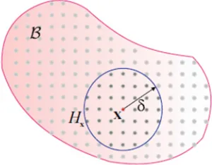
For the numerical solution of the problem, peridynamic theory [13] was utilised. Peridynamics is a new continuum mechanics formulation and it is very suitable to predict fracture initiation and propagation due to its mathematical structure. It is also advantageous to solve moving boundary problems as in the lithiation process considered in this study which is difficult to handle by using traditional techniques due to necessity of remeshing, etc. Due to its non-local characteristic [14], each material point can build up interactions with other material points within a certain distance δ (as shown in Fig.1). For material points outside this domain, it is assumed the interactions are too weak so that they can be ignored. Hence, all material points inside the domain build up the horizon (Hx) of the material point x. Each interaction
ρ!!u x
( )
,t = H f u(
( )
x′,t −u x( )
,t ,x′−x)
dVx′+b x( )
,tx
[image:6.595.220.370.122.239.2]∫
(3)Figure 1. Horizon of material point x
where b refers to the body force density and f is the pairwise force of each bond. According to bond-based peridynamic formulation used in this study, the bond force depends on the relative position and relative displacement of material points associated with this bond.
The relative position of material points, x and x′, can be expressed from the original coordinates of these points as
ξ=x′−x (4)
and the relative displacement can be calculated as
η=u
( )
x′,t −u x( )
,t (5)Hence, the stretch of a bond can be defined as
ξ ξ η
ξ + −
=
s (6)
The pairwise force for bond-based peridynamics can be expressed as [17]
f= ξ+η
ξ+η c s
(
−αCavg)
µ( )
t,ξ (7)where α is the coefficient of expansion and Cavg represents the average lithium-ion
concentration of material points x and x′, µ is the failure parameter and c is the bond constant. For two-dimensional problems and based on plane stress assumption, the bond constant can be related to Elastic modulus, E as
3 9
δ πh
E c=
where h is the thickness of the plate. Note that for bond-based peridynamics, Poisson’s ratio is constant and equal to ν=1/3 for plane stress condition.
For an elastic brittle material, it can be assumed that once a bond exceeds a critical stretch value, sc after deformation, it will break and cannot recover. The critical
stretch in peridynamic theory can be related to critical strain energy release rate. For two dimensional problems and based on plane stress assumption, critical stretch can be expressed in terms of critical strain energy release rate as
sc=
2 3
πGc
Eδ (9)
The failure condition of each bond can be represented by a failure parameter as
( )
⎩ ⎨ ⎧> ≤ =
c c
s s
s s t
0 1 ,ξ
µ (10)
Once a bond breaks, the mechanical load acting on material point x will be redistributed on remaining bonds within its horizon and mechanical condition of this point will change. The local damage of the material point x can be defined as
ϕ
( )
x,t =1− µt,ξ
( )
dVx′ Hx∫
dVx′ Hx
∫
(11)Local damage is the percentage of broken bonds associated with material point x. Local damage varies from 0 to 1 where 0 represents undamaged and 1 refers to fully damaged material point.
As mentioned earlier, the lithium-ion concentration depends on the hydrostatic stress,
!
σ . For two dimensional problems and based on plane stress assumption, hydrostatic stress of a material point x can be calculated as [15]
! σ =1
2
(
σxx+σyy)
(12)Cauchy stress tensor, σij, can be written in terms first Piola-Kirchoff stress, σ0, as
σ =Jσ0FT = σxx σxy
σyx σyy ⎡
⎣ ⎢ ⎢
⎤
⎦ ⎥
⎥ (13)
where F is the deformation gradient and J is defined as
The stress definitions are not directly used in peridynamics. However, they can be related to peridynamic parameters. Therefore, the first Piola-Kirchoff stress, σ0, can
be calculated as [18]
σ0 = H f⊗ ′
(
x −x)
dVx′ x∫
(15)Moreover, the deformation gradient, F, can also be defined in peridynamic framework as [18]
F= 2
πhδ2
1
ξ2
(
ξ+η)
⊗ξdVx′Hx
∫
(16)By recalling Eqs. (1) and (2), the mechanical stresses depend on the displacement gradients and lithium-ion concentration, while the concentration change rate depends on the hydrostatic stress gradient and lithium-ion concentration gradient. In this study, the peridynamic form of partial differential equation given in Eq. (2) is obtained by using peridynamic differential operator method developed by Madenci et al. [10].
4. Peridynamic differential operator approach
Similar to traditional finite differential schemes, peridynamic differential operator can be derived from Taylor Series [10]
f
( )
x′ = f( )
x +ξ1∂f( )
x ∂x1 +ξ2∂f
( )
x ∂x2 +1 2!ξ1
2 ∂ 2
f
( )
x ∂x12 +1 2!ξ2
2∂ 2
f
( )
x ∂x22 +ξ1ξ2∂2
f
( )
x ∂x1∂x2 +R(17)
Eq. (17) is a two dimensional second order form of Taylor Series and R represents the remainder terms which is small enough to be neglected. f is a function which depends on the problem considered. Moving the first term on the right hand side of Eq. (17) to the left hand side, multiplying each term with a peridynamic function 1 2
( )
ξ
2
p p
g (with
p1, p2 = 0, 1, 2 except p1 = p2 = 0) and integrating throughout the horizon, Eq. (17) will take a new form of
f
( )
x′ − f( )
x⎡⎣ ⎤⎦g2
p1p2
( )
ξdVx′= H
∫
x∂f
( )
x∂x1 ξ1g2
p1p2
( )
ξH
∫
xdVx′+
∂f
( )
x∂x2 ξ2g2
p1p2
( )
ξdVx′+
∂2
f
( )
x∂x12
1 2!
H
∫
xξ1 2
H
∫
xg2 p1p2
( )
ξdVx′
+∂2 f
( )
x∂x2 2
1 2!
H
∫
xξ2 2
g2 p1p2
( )
ξdVx′+
∂2
f
( )
x∂x1∂x2
ξ1ξ2 H
∫
xg2 p1p2
( )
ξdVx′
(18)
1
n1!n2!
g2
p1p2
( )
ξdVx′=δn1p1δn2p2 Hx
∫
with n1 = n2 = 0, 1, 2 (19)where δ is the Kronecker delta. By utilising Eq. (19), partial derivatives can be expressed in peridynamic form as
∂f
( )
x∂x1
∂f
( )
x∂x2
∂2 f
( )
x∂x1 2
∂2 f
( )
x∂x2 2
∂2 f
( )
x∂x1∂x2
⎧ ⎨ ⎪ ⎪ ⎪ ⎪ ⎪ ⎪ ⎪ ⎩ ⎪ ⎪ ⎪ ⎪ ⎪ ⎪ ⎪ ⎫ ⎬ ⎪ ⎪ ⎪ ⎪ ⎪ ⎪ ⎪ ⎭ ⎪ ⎪ ⎪ ⎪ ⎪ ⎪ ⎪
= ⎡⎣f
( )
x′ − f( )
x ⎤⎦ g210
( )
ξg2 01
( )
ξg220
( )
ξg2 02
( )
ξg2 11
( )
ξ⎧ ⎨ ⎪ ⎪ ⎪⎪ ⎩ ⎪ ⎪ ⎪ ⎪ ⎫ ⎬ ⎪ ⎪ ⎪⎪ ⎭ ⎪ ⎪ ⎪ ⎪
H
∫
xdVx′ (20)
The peridynamic functions 1 2
( )
ξ
2 p p
g in Eq. (20) can be constructed by polynomials which contain a weight function ω and unknown coefficients a as [10]
( )
( )
( )
( )
( )
22 11 11( )
1 2 02 02 2 1 20 20 2 01 01 1 10 10 2 2 1 2 1 2 1 2 1 2 1 2 1 ξ ξ ξ ω ξ ξ ω ξ ξ ω ξ ξ ω ξ ξ ω ξ p p p p p p p p p p p p a a a a a g + + + + = (21)The unknown coefficient matrix components a depends on a peridynamic shape matrix A and coefficient matrix b with a relationship given as
( )( )
∑ ∑
2= −= =0 2 0 1 1 2 2 1 2 1 2 1 2 1 2 1 2 1 q q q p p n n p p q q q q n
n a b
A (22)
in which q1 and q2 should not be zero at the same time.
The peridynamic shape matrix A depends on the weight functions ω and components of the relative position of interacting material points associated with a bond, ξ1,ξ2. The relationship between these parameters is given as
An
1n2
( )( )q1q2 = ωq1q2
( )
ξHx
∫
ξ1n1+p1ξ2 n2+p2dV
′
x (23)
The coefficient matrix b can be constructed as
bn 1n2 p1p2 =n
1!n2!δn1p1δn2p2 (24)
1 2 1 2 1 + + ⎟⎟⎠ ⎞ ⎜⎜⎝ ⎛ = q q q q ξ δ ω (25)
For two dimensional problems, the peridynamic shape matrix A can be written based on Eq. (23) as
A( )10( )10 A( )10( )01 A( )10( )20 A( )10( )02 A( )10( )11
A( )01( )10 A( )01( )01 A( )01( )20 A( )01( )02 A( )01( )11
A( )20( )10 A( )20( )01 A( )20( )20 A( )20( )02 A( )20( )11
A( )02( )10 A( )02( )01 A( )02( )20 A( )02( )02 A( )02( )11
A( )11( )10 A( )11( )01 A( )11( )20 A( )11( )02 A( )11( )11
⎡ ⎣ ⎢ ⎢ ⎢ ⎢ ⎢ ⎢ ⎢ ⎢ ⎤ ⎦ ⎥ ⎥ ⎥ ⎥ ⎥ ⎥ ⎥ ⎥ = 1 2πhδ
4
0 0 0 0
0 1
2πhδ
4
0 0 0
0 0 1
4πhδ
6 1
12πhδ
6
0
0 0 1
12πhδ
6 1
4πhδ
6
0
0 0 0 0 1
12πhδ
6 ⎡ ⎣ ⎢ ⎢ ⎢ ⎢ ⎢ ⎢ ⎢ ⎢ ⎢ ⎢ ⎢ ⎢ ⎢ ⎤ ⎦ ⎥ ⎥ ⎥ ⎥ ⎥ ⎥ ⎥ ⎥ ⎥ ⎥ ⎥ ⎥ ⎥ (26)
The unknown coefficient matrix a can be expressed as
[ ]
⎥ ⎥ ⎥ ⎥ ⎥ ⎥ ⎦ ⎤ ⎢ ⎢ ⎢ ⎢ ⎢ ⎢ ⎣ ⎡ = 11 11 02 11 20 11 01 11 10 11 11 02 02 02 20 02 01 02 10 02 11 20 02 20 20 20 01 20 10 20 11 01 02 01 20 01 01 01 10 01 11 10 02 10 20 10 01 10 10 10 a a a a a a a a a a a a a a a a a a a a a a a a aa (27)
According to Eq. (24), the known coefficient matrix b can be calculated as
[ ]
⎥ ⎥ ⎥ ⎥ ⎥ ⎥ ⎦ ⎤ ⎢ ⎢ ⎢ ⎢ ⎢ ⎢ ⎣ ⎡ = ⎥ ⎥ ⎥ ⎥ ⎥ ⎥ ⎦ ⎤ ⎢ ⎢ ⎢ ⎢ ⎢ ⎢ ⎣ ⎡ = 1 0 0 0 0 0 2 0 0 0 0 0 2 0 0 0 0 0 1 0 0 0 0 0 1 0 0 0 0 0 0 0 0 0 0 0 0 0 0 0 0 0 0 0 0 11 11 02 02 20 20 01 01 10 10 b b b b b b (28)After expanding the summation term in Eq. (22), the relationship between the elements of the shape coefficient matrix A, unknown coefficient matrix a and known coefficient matrix b can be expressed as:
( )( ) 1010
10 10 10
10
a
b
A
=
(29a)( )( ) 0101 01 01 01
01
a
b
A
=
(29b)( )( ) ( )( ) 2020
20 02 02 20 20 20 02
20
a
A
a
b
( )( ) ( )( ) 0202 02 02 02 02 02 20 20
02
a
A
a
b
A
+
=
(29d)( )( ) 1111
11 11 11
11
a
b
A
=
(29e)Solving the system of equations given in Eqs. (29a-e), the unknown coefficient matrix a can be obtained as
a
[ ]
= 2πhδ4 0 0 0 0
0 2
πhδ4 0 0 0
0 0 9
πhδ6 −
3
πhδ6 0
0 0 − 3
πhδ6
9
πhδ6 0
0 0 0 0 12
πhδ6 ⎡ ⎣ ⎢ ⎢ ⎢ ⎢ ⎢ ⎢ ⎢ ⎢ ⎢ ⎢ ⎢ ⎢ ⎢ ⎤ ⎦ ⎥ ⎥ ⎥ ⎥ ⎥ ⎥ ⎥ ⎥ ⎥ ⎥ ⎥ ⎥ ⎥ (30)
Substituting Eq. (30) into Eq. (21), the peridynamic functions can be calculated as
g210
( )
ξ = 2πhξ δ2 cosθ (31a)
g201
( )
ξ = 2πhξ δ2sinθ (31b)
g220
( )
ξ = 9πhξ δ3cos
2θ − 3 πhξ δ3sin
2θ (31c)
g202
( )
ξ =− 3 πhξ δ3cos2θ+ 9 πhξ δ3sin
2θ (31d)
g211
( )
ξ = 12πhξ δ3cosθsinθ (31e)
∂C
∂t =MkBT
{
C( )
x′,t −C( )
x,t}
g220
( )
ξ +g 2 02( )
ξ{
}
Hx
∫
dVx′−MCΩ
NA
{
σ!( )
x′,t −σ!( )
x,t}
g220
( )
ξ +g 2 02( )
ξ{
}
Hx
∫
dVx′− MCΩ
NA
{
C( )
x′,t −C( )
x,t}
g210
( )
ξHx
∫
dVx′⎛ ⎝
⎜ ⎞
⎠
⎟
{
σ!( )
x′,t −σ!( )
x,t}
g210( )
ξHx
∫
dVx′⎛ ⎝
⎜ ⎞
⎠ ⎟ ⎧
⎨ ⎪ ⎩⎪
⎫ ⎬ ⎪ ⎭⎪
− MCΩ
NA
{
C( )
x′,t −C( )
x,t}
g201
( )
ξHx
∫
dVx′⎛ ⎝
⎜ ⎞
⎠
⎟
{
σ!( )
x′,t −σ!( )
x,t}
g201( )
ξHx
∫
dVx′⎛ ⎝
⎜ ⎞
⎠ ⎟ ⎧
⎨ ⎪ ⎩⎪
⎫ ⎬ ⎪ ⎭⎪
(32)
5. Validation study
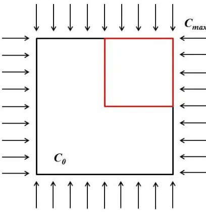
Figure 3. Two-dimensional square plate specimen
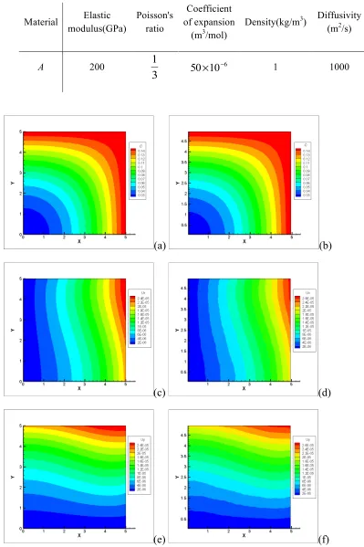
Table 1. Material properties for validation case
Material Elastic modulus(GPa)
Poisson's ratio
Coefficient of expansion
(m3/mol)
Density(kg/m3) Diffusivity
(m2/s)
A 200
3
1 6
10
50× − 1 1000
(a) (b)
(c) (d)
(e) (f)
Figure 4. Comparison of PD results against FEM results: (a) Lithium ion concentration distribution by FEM (b) Lithium ion concentration distribution by PD
6. Numerical studies
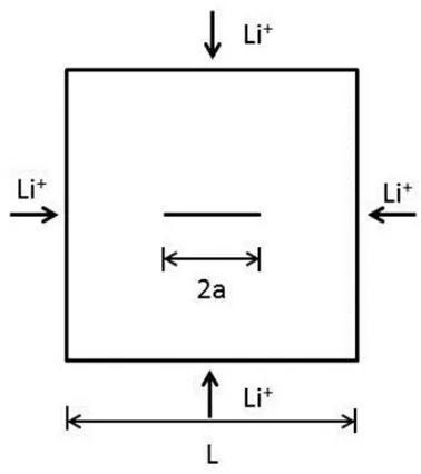
[image:16.595.201.390.381.594.2]To demonstrate the capability of the current approach, a square silicon plate is selected to represent the anode plate of the lithium ion battery based on the study considered by Zuo and Zhao [8]. Both pure silicon and lithiated silicon are regarded as brittle materials. Concentration values are normalised by maximum concentration. The thickness of the specimen plate is negligible compared with boundary length. Therefore, plane stress assumption is utilised in order to simplify the numerical simulation. The square specimen is free from lithium-ions at its initial state (see Fig. 5). The silicon specimen is subjected to maximum lithium-ion concentration on all of its boundaries by introducing a fictitious region with a thickness of horizon size along its boundaries [29]. The plate is free from any displacement constraints. Geometrical and material information are summarised in Table 2. Note that bond-based peridynamics is used in this study which enforces a constraint condition on Poisson’s ratio, i.e. ν=1/3, which is higher than the actual Poisson’s ratio values given for silicon and lithiated silicon. For the cases which are considered in this study, the effect of Poisson’s ratio on the fracture pattern is not significant. However, if required, actual Poisson’s ratio values can be specified using ordinary state based peridynamic formulation for the equation of motion [27].
Table 2. Geometrical and material parameters
L Length of the specimen 1µm
silicon
E Elastic constant of silicon 80GPa
4 15Si Li
E Elastic constant of amorphous Li15Si4 41GPa
silicon
ν
Poisson's ratio of silicon 0.224 15Si
Li
ν Poisson’s ratio of silicon 0.24
Ω Partial molar volume 8.5×10⁻⁶m3mol−1
M Molecular mobility 500m2J−1s−1
B
k Boltzmann constant 1.38×10⁻²³J⋅K−1
T Absolute temperature 300K
A
N Avogadro's constant 6.02×10²³mol−1
Si c
s _ Critical strain for silicon 0.04
sc_Li15Si4 Critical strain for amorphous Li15Si4 0.035
max
C Maximum concentration 1.18×10⁴molm−3
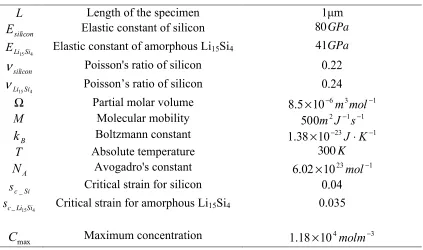
6.1. Coupled analysis for a single crack case
(a) (b)
[image:18.595.107.498.79.373.2](c) (d)()
Figure 6. Results for an electrode plate with a single crack: (a) Initial damage (b) Damage after deformation (c) Lithium ion concentration (d) Hydrostatic stress
6.2. Coupled analysis for multiple crack cases
Due to unexpected factors such as manufacturing quality and damage occurance during transportation, electrodes may have multiple pre-existing cracks. Hence, single crack may not be sufficient for describing the condition of damage in a battery electrode. In these case studies, an electrode plate with multiple cracks with different orientations are investigated.
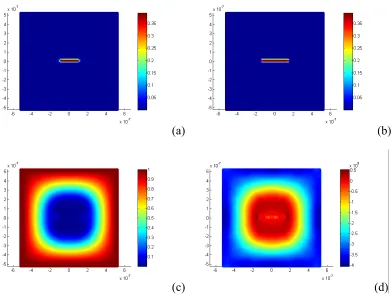
6.2.1. Twin horizontal cracks
(a) (b)
[image:19.595.104.506.79.389.2](c) (d)
Figure 7. Results for an electrode plate with twin cracks: (a) Initial damage (b) Damage after deformation (c) Lithium ion concentration (d) Hydrostatic stress
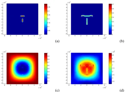
6.2.2. Perpendicular and oblique crack cases
(a) (b)
[image:20.595.106.507.80.377.2](c) (d)
Figure 8. Results for an electrode plate with perpendicular cracks: (a) Initial damage (b) Damage after deformation (c) Lithium ion concentration (d) Hydrostatic stress
(a) (b)
Figure 9. Results for an electrode plate with oblique cracks: (a) Initial damage (b) Damage after deformation (c) Lithium ion concentration (d) Hydrostatic stress
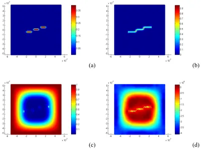
6.2.3. Triple horizontal crack case
Cracks in battery electrode may have arbitrary arrangements in terms of crack numbers and crack orientations. In this case, a triple crack damage situation is under investigation. Cracks with the same length equivalent to 10% of the plate length located at the central plate region are shown in Fig. (10a). Since cracks are located close to each other, particles between cracks have fewer interactions with neighbouring particles within their horizons. Therefore, the stiffnesses of these particles are relatively weaker. Hence, propagation of some cracks is led by neighbouring cracks. Central crack propagates towards neighbouring cracks from both crack tips and merges all three cracks into one crack as shown in Fig. (10b). Then, the propagation of outer crack tips continues horizontally along its initial crack path. High hydrostatic stresses exist at outer crack tips and the stresses at inner crack tips reduce since cracks already merge with each other as shown in Fig. (10d).
(a) (b)
[image:21.595.106.511.346.650.2](c) (d)
Figure 10. Results for an electrode plate with triple cracks: (a) Initial damage (b) Damage after deformation (c) Lithium ion concentration (d) Hydrostatic stress
6.3. Coupled analysis for randomly oriented multiple crack case
electrode plate after several cycling process, coupled field diffusion analysis for battery electrode with randomly oriented multiple crack cases are under investigation in this section. Two damage situations with six cracks and eleven cracks were chosen as shown in Fig. (11a) and Fig. (12a). All cracks have the same crack length equivalent to 10% of the specimen length and they are randomly oriented at the central plate region. As lithium-ions diffuse into crack tip regions, hydrostatic stress increases dramatically at the crack tips, especially at the outer crack tips. Meanwhile, some cracks start to propagate and merge with neighbouring cracks. Once small cracks merge into a large crack, hydrostatic stress at crack tip regions reduce which may be the reason that the remaining small cracks stop propagating. In other words, the newly formed large crack prevents small cracks to propagate. On the other hand, outer crack tips will not be affected by other cracks and propagate along their crack paths toward high concentration region.
(a) (b)
[image:22.595.107.511.298.594.2](c) (d)
(a) (b)
[image:23.595.108.508.81.389.2](c) (d)
Figure 12. Result for an electrode plate with eleven randomly oriented cracks: (a) Initial damage (b) Damage after deformation (c) Lithium ion concentration (d) Hydrostatic stress
7. Conclusion
In this study, a new continuum mechanics formulation, peridynamics, in conjunction with the newly developed peridynamic differential operator approach is utilised to analyse the fracture and failure analysis of lithium-ion battery plates with pre-existing cracks. According to the numerical results, high hydrostatic stress at the crack tip is the main motivation of crack propagation and it is reflected on bond breakage in peridynamic theory. Besides, phase change from pure silicon and lithiated silicon during the lithiation process also affects crack propagation. As hydrostatic stress increases at the crack tip region, lithium-ion concentration increases as well and leads to higher concentration value at the crack tip regions. Although lithium-ion battery electrode may have various damage situations, cracks normally propagate through particles with weak stiffness and high hydrostatic stress. Hence, for multi-crack situations, some of the cracks merge into a larger crack first and then propagate from outer crack tips. Due to the crack merging process, high hydrostatic stress at some of the crack tips reduces and this may arrest remaining cracks.
peridynamics, we can have a better understanding on failure mechanisms in lithium ion batteries.
7. References
1. Daniel, C., 2008. Materials and processing for lithium-ion batteries. Jom, 60(9), pp.43-48.
2. Chan, C.K., Peng, H., Liu, G., McIlwrath, K., Zhang, X.F., Huggins, R.A. and Cui, Y., 2008. High-performance lithium battery anodes using silicon nanowires. Nature nanotechnology, 3(1), pp.31-35.
3. Maranchi, J.P., Hepp, A.F. and Kumta, P.N., 2003. High capacity, reversible silicon thin-film anodes for lithium-ion batteries. Electrochemical and solid-state letters, 6(9), pp.A198-A201.
4. Choi, J.W., Cui, Y. and Nix, W.D., 2011. Size-dependent fracture of Si nanowire battery anodes. Journal of the Mechanics and Physics of Solids, 59(9), pp.1717-1730.
5. Liu, P., Sridhar, N. and Zhang, Y.W., 2012. Lithiation-induced tensile stress and surface cracking in silicon thin film anode for rechargeable lithium battery. Journal of Applied Physics, 112(9), p.093507.
6. Stamps, M.A. and Huang, H.Y.S., 2012, November. Mixed modes fracture and fatigue evaluation for lithium-ion batteries. In ASME 2012 International Mechanical Engineering Congress and Exposition (pp. 97-103). American Society of Mechanical Engineers.
7. Grantab, R. and Shenoy, V.B., 2012. Pressure-gradient dependent diffusion and crack propagation in lithiated silicon nanowires. Journal of the Electrochemical Society, 159(5), pp.A584-A591.
8. Zuo, P. and Zhao, Y.P., 2015. A phase field model coupling lithium diffusion and stress evolution with crack propagation and application in lithium ion batteries. Physical Chemistry Chemical Physics, 17(1), pp.287-297.
9. Gao, Y.F. and Zhou, M., 2013. Coupled mechano-diffusional driving forces for fracture in electrode materials. Journal of Power Sources, 230, pp.176-193.
10.Madenci, E., Barut, A. and Futch, M., 2016. Peridynamic differential operator and its applications. Computer Methods in Applied Mechanics and Engineering, 304, pp.408-451.
11.Shenoy, V.B., Johari, P. and Qi, Y., 2010. Elastic softening of amorphous and crystalline Li–Si phases with increasing Li concentration: a first-principles study. Journal of Power Sources, 195(19), pp.6825-6830.
13.Silling, S.A. and Askari, E., 2005. A meshfree method based on the peridynamic model of solid mechanics. Computers & structures, 83(17), pp.1526-1535.
14.Oterkus, S., Madenci, E. and Agwai, A., 2014. Fully coupled peridynamic thermomechanics. Journal of the Mechanics and Physics of Solids, 64, pp.1-23.
15.Malvern, L.E., 1969. Introduction to the Mechanics of a Continuous Medium (No. Monograph).
16.Li, J., Dozier, A.K., Li, Y., Yang, F. and Cheng, Y.T., 2011. Crack pattern formation in thin film lithium-ion battery electrodes. Journal of The Electrochemical Society, 158(6), pp.A689-A694.
17.Oterkus, S., Madenci, E., Oterkus, E., Hwang, Y., Bae, J. and Han, S., 2014, May. Hygro-thermo-mechanical analysis and failure prediction in electronic packages by using peridynamics. In Electronic Components and Technology Conference (ECTC), 2014 IEEE 64th (pp. 973-982). IEEE.
18.Zimmermann, M., 2005. A continuum theory with long-range forces for solids (Doctoral dissertation, Massachusetts Institute of Technology).
19.Silling, S.A., 2000. Reformulation of elasticity theory for discontinuities and long-range forces. Journal of the Mechanics and Physics of Solids, 48(1), pp.175-209.
20.Ren, H., Zhuang, X., Cai, Y. and Rabczuk, T., 2016. Dual-horizon peridynamics. International Journal for Numerical Methods in Engineering, 108(12), pp.1451-1476.
21.Dipasquale, D., Zaccariotto, M. and Galvanetto, U., 2014. Crack propagation with adaptive grid refinement in 2D peridynamics. International Journal of Fracture, 190(1-2), pp.1-22.
22.Diyaroglu, C., Oterkus, E., Madenci, E., Rabczuk, T. and Siddiq, A., 2016. Peridynamic modeling of composite laminates under explosive loading. Composite Structures, 144, pp.14-23.
23.Oterkus, E. and Madenci, E., 2012. Peridynamic theory for damage initiation and growth in composite laminate. In Key Engineering Materials (Vol. 488, pp. 355-358). Trans Tech Publications.
24.De Meo, D., Diyaroglu, C., Zhu, N., Oterkus, E. and Siddiq, M.A., 2016. Modelling of stress-corrosion cracking by using peridynamics. International journal of hydrogen energy, 41(15), pp.6593-6609.
26.Madenci, E. and Oterkus, E., 2014. Peridynamic theory and its applications. New York: Springer.
27.Silling, S.A., Epton, M., Weckner, O., Xu, J. and Askari, E., 2007. Peridynamic states and constitutive modeling. Journal of Elasticity, 88(2), pp.151-184.
28.Fick, A., 1995. On liquid diffusion. Journal of Membrane Science, 100(1), pp.33-38.