
Rochester Institute of Technology
RIT Scholar Works
Theses Thesis/Dissertation Collections
2011
Introduction to IP multicast in production
networks
Ganesh Vidyadharan Girija
Follow this and additional works at:http://scholarworks.rit.edu/theses
This Master's Project is brought to you for free and open access by the Thesis/Dissertation Collections at RIT Scholar Works. It has been accepted for inclusion in Theses by an authorized administrator of RIT Scholar Works. For more information, please [email protected].
Recommended Citation
i
ROCHESTER INSTITUTE OF TECHNOLOGY
COLLEGE OF APPLIED SCIENCE AND TECHNOLOGY
DEPARTMENT OF ELECTRICAL, COMPUTER &
TELECOMMUNICATIONS ENGINEERING TECHNOLOGY
Introduction to
IP Multicast in production
networks
By
Ganesh Vidyadharan Girija
9/29/2011
Project submitted is in partial fulfillment of the requirements
for the degree of Master of Science in Telecommunications
Allproval
Ganesh Vidyadharan Girija Project approved
by:
Professor Ronald G Fulle
Professor Mark J. Indelicato
Professor William P. Johnson
Date: September
29th,
2011
iii
1 Introduction ... 1
2 Multicast Basics ... 4
2.1 Multicast Addresses ... 4
2.2 Assigned Multicast Addresses ... 4
2.2.1 Link-Local Multicast Addresses ... 5
2.2.2 Other Reserved Addresses ... 6
2.2.3 Administratively Scoped Multicast Addresses ... 6
2.3 Multicast Distribution Trees ... 7
2.3.1 Source Trees ... 7
2.3.2 Shared Trees ... 8
2.3.2.1 Bidirectional Shared Trees ... 9
2.3.2.2 Unidirectional Shared Trees ... 10
2.4 Multicast Forwarding ... 12
2.4.1 Reverse Path Forwarding... 12
2.4.2 Multicast Forwarding Cache ... 14
2.4.3 TTL Thresholds ... 15
2.4.4 Administratively Scoped Boundaries ... 16
2.5 Multicast Routing Protocol Categories ... 18
2.5.1 Dense Mode Protocols ... 18
2.5.2 Sparse Mode Protocols ... 20
2.5.3 Link-State Protocols ... 23
2.6 Summary ... 23
3 Internet Group Management Protocol ... 24
3.1 IGMP Version 1 ... 24
3.1.1 IGMPv1 Message Format ... 25
3.1.2 The IGMPv1 Query-Response Process ... 26
3.1.3 Report Suppression Mechanism ... 27
3.1.4 IGMPv1 Querier ... 28
3.1.5 The IGMPv1 Join Process ... 28
3.1.6 The IGMPv1 Leave Process ... 29
3.2 IGMP Version 2 ... 30
3.2.1 IGMPv2 Message Format ... 31
3.2.2 Query-Response Tuning ... 32
3.2.3 IGMPv2 Leave Group Messages ... 34
3.2.4 IGMPv2 Group-Specific Query Messages ... 34
3.3 IGMPv2 Leave Process ... 34
3.4 Querier Election Process ... 36
3.5 Summary ... 37
4 Distance Vector Multicast Routing Protocol ... 38
4.1 DVMRP Neighbor Discovery ... 38
4.2 DVMRP Route Table ... 39
4.3 Exchanging DVMRP Route Reports ... 40
4.4 DVMRP Truncated Broadcast Trees ... 42
4.5 DVMRP Scalability... 45
4.6 Summary ... 45
5 PIM Dense Mode ... 46
5.1 PIM Neighbor Discovery ... 46
5.1.1 PIM Hello Messages ... 47
5.1.2 PIM-DM Designated Router ... 47
5.2 PIM-DM Source Distribution Trees ... 48
5.3 PIM-DM Asserts ... 51
5.4 PIM-DM Scalability ... 53
5.5 Summary ... 54
iv
6 PIM Sparse Mode ... 55
6.1 Explicit Join Model ... 55
6.2 PIM-SM Shared Trees ... 56
6.2.1 Shared Tree Joins ... 56
6.2.2 Shared Tree Prunes ... 59
6.3 PIM-SM Shortest Path Trees ... 61
6.3.1 Shortest Path Tree Joins ... 61
6.3.2 Shortest Path Tree Prunes ... 63
6.4 PIM Join/Prune Messages ... 65
6.5 PIM-SM State-Refresh ... 66
6.6 Source Registration ... 67
6.6.1 PIM Register Messages ... 67
6.6.2 PIM Register-Stop Messages ... 69
6.7 Shortest Path Tree Switchover ... 70
6.7.1 Pruning Sources from the Shared Tree ... 72
6.8 PIM-SM Designated Router ... 73
6.8.1 The Role of the Designated Router ... 74
6.8.2 Designated Router Failover ... 74
6.9 RP Discovery ... 75
6.10 PIM-SM Suitability/Scalability ... 75
6.11 Summary ... 76
7 Core-Based Trees ... 77
7.1 CBT Overview ... 77
7.2 CBT Version 3 ... 79
7.3 CBT Suitability/Scalability ... 80
7.4 Summary ... 80
8 Multicast Open Shortest Path First ... 81
8.1 MOSPF Suitability/Scalability ... 81
8.2 Summary ... 82
9 Multicast Applications ... 83
9.1 Multimedia Conferencing... 83
9.2 Data Distribution ... 84
9.3 Real-Time Data Multicasts ... 84
9.4 Gaming and Simulations ... 84
9.5 MBone---The Internet’s Multicast Backbone ... 85
9.5.1 MBone Sessions ... 86
9.5.2 History of the MBone ... 86
9.5.3 Today’s MBone Architecture ... 88
9.5.4 Tomorrow’s MBone Architecture ... 89
9.6 Summary ... 89
10 Conclusions ... 90
10.1 The Pros of IP Multicast ... 90
10.1.1 Bandwidth ... 90
10.1.2 Server Load ... 91
10.1.3 Network Loading ... 92
10.2 The Cons of IP Multicast... 93
10.2.1 Unreliable Packet Delivery ... 93
10.2.2 Packet Duplication ... 93
10.2.3 Network Congestion ... 94
v &/'hZ /WZK^d/E'>K<zZKhdZ &/'hZ Dh>d/^dZ^^&KZDd &/'hZ ,K^d^,KZd^dWd,dZ &/'hZ ,K^d^,KZd^dWd,dZ &/'hZ ^,Z/^dZ/hd/KEdZ &/'hZ //Zd/KE>^,ZdZ &/'hZ hE//Zd/KE>^,ZdZh^/E'^Wd^dK'ddZ&&/dKd,ZKKd &/'hZ d//Zd/KE>^,ZdZh^/E'hE/^ddK'ddZ&&/dKd,ZKKd &/'hZ ZW&,<&/>^ &/'hZ ZW&,<^h^ &/'hZ dd>d,Z^,K>^ &/'hZ dd>d,Z^,K>KhEZ/^ &/'hZ D/E/^dZd/sKhEZzD,E/^D &/'hZ D/E/^dZd/s>z^KWKhEZ/^ &/'hZ WZhE/E'E^DK&>Kt &/'hZ E^DK'Z&d/E' &/'hZ ^,ZdZ:K/ED^^' &/'hZ ^Wd:K/ED^^'^ &/'hZ ^WZ^DKWZhE
&/'hZ /'DWs D^^'&KZDd
&/'hZ /'DWs YhZz Z^WKE^WZK^^
&/'hZ /'DWs :K/EWZK^^
&/'hZ /'DWs >s'ZKhWd/D/E'
&/'hZ /'DWs D^^'&KZDd
&/'hZ /'DWs YhZz Z^WKE^dhE/E'
&/'hZ Z^/E'Z^WKE^hZ^d/E^^
&/'hZ /'DWs >sWZK^^ ,K^d, >s^
&/'hZ /'DWs >sWZK^^ , >s^
&/'hZ /'DWs >s'ZKhWd/D/E'
&/'hZ sDZWE/',KZ/^KsZz
&/'hZ sDZWZKhdy,E' /E/d/>^dd
&/'hZ sDZWZKhdy,E' ^dW^ E
&/'hZ sDZWZKhdy,E' ^dW
&/'hZ sDZWZKhdy,E' ^dW^ E
&/'hZ sDZWdZhEdZK^ddZ
&/'hZ Z^h>d/E'dZhEdZK^ddZ&KZEdtKZ<^
&/'hZ dZhEdZK^ddZ&KZEdtKZ<^
&/'hZ W/D D/^dZ/hd/KEdZ /E/d/>&>KK/E'
&/'hZ ^DW>EdtKZ<
&/'hZ W/D^^ZdD,E/^D
&/'hZ W/D^^ZdyDW>
&/'hZ W/D^,ZdZ:K/E^ ^dW
&/'hZ W/D^,ZdZ:K/E ^dW
&/'hZ ^,ZdZ:K/E^ ^dW
&/'hZ ^,ZdZ:K/E^ ^dW
&/'hZ ^,ZdZ:K/E^ ^dW
&/'hZ ^,ZdZ:K/E^ ^dW
&/'hZ ^,ZdZWZhE^ ^dW
&/'hZ ^,ZdZWZhE^ ^dW
&/'hZ ^,ZdZWZhE^ ^dW
&/'hZ ^Wd:K/E ^dW
vi
&/'hZ ^Wd:K/E ^dW
&/'hZ ^Wd:K/E ^dW
&/'hZ ^WdWZhE^ ^dW
&/'hZ ^WdWZhE^ ^dW
&/'hZ ^WdWZhE^ ^dW
&/'hZ ^KhZZ'/^dZd/KE ^dW
&/'hZ ^KhZZ'/^dZd/KE ^dW
&/'hZ ^KhZZ'/^dZd/KE ^dW
&/'hZ ^KhZZ'/^dZd/KE ^dW
&/'hZ ^KhZZ'/^dZd/KE ^dW
&/'hZ ^Wd^t/d,KsZ ^dW
&/'hZ ^Wd^t/d,KsZ ^dW
&/'hZ WZhE/E'^KhZ^&ZKDd,^,ZdZ ^dW
&/'hZ WZhE/E'^KhZ^&ZKDd,^,ZdZ ^dW
&/'hZ WZhE/E'^KhZ^&ZKDd,^,ZdZ ^dW
&/'hZ W/D ^D^/'EdZKhdZ
&/'hZ dZ&&/&>KtKEd^
&/'hZ ^hKWd/D>dZ&&/&>Kt
&/'hZ DKE'ZKtd,
&/'hZ hE/^dsZ^h^Dh>d/^dEt/d,&KZh/K
&/'hZ hE/^dsZ^h^Dh>d/^dEt/d,&KZs/K
&/'hZ ^ZsZ>K
vii
Abstract
1
1 Introduction
We are living in an age that is witnessing the fastest pace in the growth of Information Technology and this growth is facilitated by the networking infrastructure that binds the communication world. While the information carrying capacity of transport layer has been increased manifold by the advancements in fiber optic communication, the efficient utilization of the available network infrastructure is being honed by development of various layer 2/3 protocols. Most of the developmental studies are aimed at achieving the goal of optimal utilization of the available bandwidth, which comes at a cost.
One such topic that is gaining popularity is the development of Multicast Networks. Multicasting is based on a specific scheme of IP addressing and making use of it to optimize the bandwidth utilization. The role of multicasting is to minimize the number of packets that are sent as duplicates when communication is happening between groups of select devices in a network. Examples of these could be a training session for employees in a particular department, sharing trading information to a group of members, paging a message to a specific group, IPTV applications, etc. This paper will cover the basics of IP Multicasting including the IP addressing scheme, the basic protocols used in Multicast routing, the mechanism used to communicate between the hosts in a network and the first hop routers about its intent to join/leave a multicast group and a quick look on the applications that use IP multicasting and the advantages that it offers when compared to using unicast as the method of choice from an application perspective. But, before going into the details of Multicast Communication, here is a briefing on the common methods of group communication between devices in a network, which are Unicast Communication and Broadcast Communication.
Unicast
2 device sending 100Kbps packets to a bunch of devices, say 10, the total bandwidth utilization will be 1000Kbps even though the same information is being sent in all the 10 packets flowing across the same network infrastructure. In the following pages of this paper, we will go over the advancements in communication that will help to keep the bandwidth usage to a minimum irrespective of the number of recipients.
Broadcast
This method is used for sending packets to all devices in the network i.e. one to all communication. Broadcast packets are not forwarded by routers, so as to avoid flooding of packets in large networks.
Figure 1: IP Broadcast being blocked by a Router [2]
Broadcast can be done over UDP only. Broadcast packets use all 1’s in destination IP field. It is also possible to do directed broadcast for specific networks. For example, if a device with host IP of 192.168.15.3 wants to send a broadcast to all devices in the 192.168.15.0/24 network, the broadcast packets destination IP will be 192.168.15.255, which means that all the devices in the network will receive that packet.
3 Why Multicast?
Optimal use of the available network bandwidth is one of the main goals of a network design. There are lots of applications that involve communication between select groups of devices which are part of a larger network. Some of the fast growing examples are networked gaming applications and IPTV along with other traditional information sharing fields like stock trading firms, medical transcription, online education systems, etc that can take advantage of developments in selective broadcasting. Using unicast for these applications means that the number of packets containing the same information has to be replicated a number of times depending on the number of recipients, while using broadcast would mean that there would be a bunch of devices that receive some junk packets or in some cases open up security concerns depending on the criticality of the information being shared.
Multicast routing requires the presence of Multicast aware routing devices in the network. This is the reason why the earlier deployment of multicast networks would be seen in the private networks of large corporations, than on the internet where there would be a whole lot of old school devices that are not multicast enabled. The multicast enabled routers in the network will have the responsibilities of duplicating the packets received from the source on its outgoing interfaces depending on the presence of recipients on its outgoing interface. This ensures that there is only one source packet irrespective of the number of recipients in the network. “Multicast in corporate environments where all routers are multicast-enabled can save quite a bit of bandwidth. “ [1]
4
2 Multicast Basics
The idea of this part is to introduce some of the common terminologies related to IP Multicasting, like IP multicast address itself, sending and receiving of IP multicast packets, and IGMP v1 (Internet Group Management Protocol) along with multicast distribution trees and multicast forwarding.
2.1 Multicast Addresses
“ Multicast addressing is different from the regular unicast addressing. While the devices participating in unicast are identifiable with unique IP’s, the devices participating in multicast are identified by an arbitrary group of IP hosts specified by the multicast IP addresses, for the hosts that have joined a multicast group or wishing to receive traffic sent to the group.” [2] The multicast addresses belong to the IANA assigned Class D address space, which ranges from 224.0.0.0 to 239.255.255.255. These IP’s are identified by 1110 in the first four places of the first octet, in binary format.
Figure 2: Multicast Address Format [2]
2.2 Assigned Multicast Addresses
5 This leaves the rest of the world to share the remaining IP’ s on a lease basis like we do with DHCP IP allocation.
2.2.1 Link-Local Multicast Addresses
“ The IANA has reserved the range of 224.0.0.0 through 224.0.0.255 for use by network protocols on a local network segment. Packets with an address in this range are local in scope, are note forwarded by IP routers and therefore go no further than the local network.
The table 2-1 is a partial list of reserved multicast addresses taken directly from the IANA database. The table lists the reserved link-local address, the network protocol function to which they have been assigned, and the person that requested the address or the RFC associated with the protocol.” [2]
Table 2-1: Link-Local Multicast Addresses
Address
Usage
Reference
224.0.0.1
All Hosts
[RFC 1112, JBP]
224.0.0.2
All Multicast Routers
[JBP]
224.0.0.3
Unassigned
[JBP]
224.0.0.4
DVMRP Routers
[RFC 1075, JBP]
224.0.0.5
OSPF Routers
[RFC 1583, JXM1]
224.0.0.6
OSPF Designated Routers
[RFC 1583, JXM1]
224.0.0.7
ST Routers
[RFC 1190, KS14]
224.0.0.8
ST Hosts
[RFC 1190, KS14]
224.0.0.9
RIP2 Routers
[RFC 1723, SM11]
224.0.0.10
IGRP Routers
[Farinacci]
224.0.0.11
Mobile-Agents
[Bill Simpson]
224.0.0.12
DHCP Server/Relay Agent
[RFC 1884]
224.0.0.13
All PIM Routers
[Farinacci]
224.0.0.14
RSVP-Encapsulation
[Braden]
224.0.0.15
All CBT Routers
[Ballardie]
224.0.0.16
Designated-SBM
[Baker]
224.0.0.17
All SBMS
[Baker]
224.0.0.18
VRRP
[Hinden]
224.0.0.19 to
6
2.2.2 Other Reserved Addresses
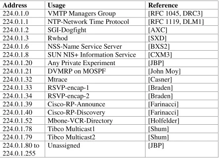
“ The IANA typically assigns single multicast address requests for network protocols or network applications out of the 224.0.1.xxx address range. Multicast routers will forward these multicast addresses, unlike multicast address in the 224.0.0.xxx address range, which are local in scope and are never forwarded by routers.
[image:14.612.76.517.269.591.2]The table 2-2 is a partial list of these single multicast address assignments.” [2]
Table 2-2: Other Reserved Multicast Addresses
Address
Usage
Reference
224.0.1.0
VMTP Managers Group
[RFC 1045, DRC3]
224.0.1.1
NTP-Network Time Protocol
[RFC 1119, DLM1]
224.0.1.2
SGI-Dogfight
[AXC]
224.0.1.3
Rwhod
[SXD]
224.0.1.6
NSS-Name Service Server
[BXS2]
224.0.1.8
SUN NIS+ Information Service
[CXM3]
224.0.1.20
Any Private Experiment
[JBP]
224.0.1.21
DVMRP on MOSPF
[John Moy]
224.0.1.32
Mtrace
[Casner]
224.0.1.33
RSVP-encap-1
[Braden]
224.0.1.34
RSVP-encap-2
[Braden]
224.0.1.39
Cisco-RP-Announce
[Farinacci]
224.0.1.40
Cisco-RP-Discovery
[Farinacci]
224.0.1.52
Mbone-VCR-Directory
[Holfelder]
224.0.1.78
Tibco Multicast1
[Shum]
224.0.1.79
Tibco Multicast2
[Shum]
224.0.1.80 to
224.0.1.255
Unassigned
[JBP]
2.2.3 Administratively Scoped Multicast Addresses
7
2.3 Multicast Distribution Trees
To understand the flow of multicast traffic in a network it is important to know the models or modes of multicast transmission that is designed to control the traffic flow. Unlike unicast transmission where it is host to host traffic over a network link, multicast works on a tree model better known as multicast distribution trees. Here the traffic is send from a source often referred to as the root of the distribution tree, to a bunch of arbitrary group of hosts, represented by the multicast group address which can be seen as the branches of the tree.
The distribution trees define the path taken by the IP multicast traffic in the network ensuring that the packets are delivered to all receivers. “ Two basic types of multicast distribution trees are source trees and shared trees.” [2]
2.3.1 Source Trees
“ The simplest form of multicast distribution tree is a source tree whose root is the source of the multicast traffic and whose branches form a spanning tree through the network to the receivers. Because this tree uses the shortest path through the network, it also is referred to frequently as a shortest path tree (SPT).
Figure 3 shows an example of an SPT for group 224.1.1.1 rooted at the source, Host A, and connecting two receivers, Hosts B and C.” [2]
8 “ The special notation of (S, G) pronounced “ S comma G” , enumerates an SPT where S is the IP address of the source and G is the multicast group address.” [2]. Hence, the multicast group in the above example can be notated as (192.1.1.1, 224.1.1.1).
[image:16.612.157.442.266.474.2]This notation also emphasizes the point that there is no direct one to one communication with respect to multicast communication. For example, if Host B is sending traffic back to the group 224.1.1.1 which has Host A and C as recipients, there will be another SPT noted as (192.2.2.2, 224.1.1.1), shown in Figure 4. There will be a separate tree for every source in this set up.
Figure 4: Host B Shortest Path Tree [2]
2.3.2 Shared Trees
“ Unlike source trees that have their roots at the source, shared trees use a single common root placed at some chosen point in the network. Depending on the multicast routing protocol, this root is often called a rendezvous point (RP) or core, which lends itself to shared trees’ other common names: RP Trees (RPT) or core-based trees (CBT).
9 Figure 5: Shared Distribution Tree [2]
This particular example has two sources, Host A and Host D sending multicast group traffic to the shared root as shown in the diagram, which is Router D. This traffic then flows down the tree to the two receivers Host B and Host C. In Source tree, each source had its own tree with the source as the root, but in this case since any source in the group will share the same root, the notation for this would be a wild card notation represented as (*,G), pronounced as “ star comma G” . This notation represents *, any source and G is the multicast group address. The tree in the example can be named (*, 224.2.2.2).
2.3.2.1 Bidirectional Shared Trees
“ Shared trees can be subdivided into two types: unidirectional and bidirectional. In the bidirectional case, multicast traffic may flow up and down the shared tree to reach all receivers. Figure 6 shows an example of a bidirectional shared tree.
Notice that multicast traffic from Host B is being forwarded by its first hop router up the tree
10 Figure 6: Bidirectional Shared Tree [2]
2.3.2.2 Unidirectional Shared Trees
Unidirectional shared trees allow multicast traffic to flow down the shared tree from root to receivers. So, with reference to the example in figure 6, the traffic from Source B will not be able to use the link between Router B and Router D as part of the multicast group to send the source traffic to the shared root. “ The source of multicast traffic must use some other means to first get the traffic to the root so that it can be forwarded down the shared tree” . [2]
“ One method that can be used is to have the root join an SPT rooted at the source to pull the traffic to the root for forwarding down the shared tree. Figure 7 shows a unidirectional shared tree where the root has joined the SPT to source Host B to pull Host B's multicast traffic to the root. When the root receives the traffic, it is forwarded down the shared tree to the other receivers. Protocol Independent Multicast (PIM) uses this method to get source multicast traffic to the root or RP.
11 Figure 7: Unidirectional Shared Tree Using SPTs to Get Traffic to the Root [2]
Figure 8: CBT Bidirectional Shared Tree Using Unicast to Get Traffic to the Root [2]
[image:19.612.124.473.330.570.2]12
2.4 Multicast Forwarding
The basic concept of packet forwarding in Multicast is a little bit different from the usual unicast model. In unicast model, the traffic flows between the source and destination in a single path, where in the intermediate routers forward the traffic to the next hop interface, based on the combined information from the destination address field in the IP packet and the routing table in the router. “ In the multicast model, the source is supposed to send traffic to an arbitrary group of hosts represented by the multicast group address in the destination address field of the IP packet.” [2] Unlike unicast model, the forwarding decision is not based on the destination address in the IP packet, but the router may end up forwarding the traffic to more than one out going interfaces in order to ensure the delivery of the packets to all participants, hence making it a complex process.
The basic multicast forwarding process used in most of the multicast routing protocols is called Reverse Path Forwarding (RPF), is explained in this section along with information on multicast forwarding caches, TTL thresholds, and administratively scoped boundaries.
2.4.1 Reverse Path Forwarding
“ Virtually all IP multicast routing protocols make use of some form of RPF or incoming interface check as the primary mechanism to determine whether to forward or drop an incoming multicast packet. When a multicast packet arrives at a router, the router performs an RPF check on the packet. If the RPF check is successful, the packet is forwarded; otherwise, it is dropped.
For traffic flowing down a source tree, the RPF check mechanism works as follows:
1. The router examines the source address of the arriving multicast packet to determine whether the packet arrived via an interface that is on the reverse path back to the source.
2. If the packet arrives on the interface leading back to the source, the RPF check is successful and the packet is forwarded.
13 The method used to determine if the packets was received from an interface traceable back to the source could vary, depending on the routing protocol in use. Some multicast routing protocols uses its own routing table to make this decision, while some other use the already available unicast routing table. An example for the former is the Distance Vector Multicast Routing Protocol (DVMRP), whereas “ PIM and CBT are examples of multicast protocols that typically use the unicast routing table to perform the RPF check. PIM and CBT are not limited to using just the unicast routing table for the RPF check, however. They also can use reachability information from a DVMRP router table or a Multicast Border Gateway Protocol (MBGP) route table, or they can statically configure RPF information.
Figure 9 illustrates the RPF check process. This example uses a separate multicast routing table, although the concept is the same if the unicast routing table or some other reachability table is used.
Figure 9: RPF Check Fails [2]
A multicast packet from source 151.10.3.21 is received on interface S0. A check of the multicast routing table shows that the interface on the reverse path back to the source is S1, not S0. Therefore, the RPF check fails, and the packet is discarded.
Figure 10 is another example of a multicast packet from source 151.10.3.21 arriving at the router, this time via interface S1.
14 In this case, the RPF check succeeds as interface S1 is on the reverse path back to the source, and therefore the packet is forwarded to all interfaces on the outgoing interface list. (Notice that the outgoing interfaces don’t have to necessarily include all interfaces on the router.)” [2]
2.4.2 Multicast Forwarding Cache
As explained in the previous section, determining the authenticity of the source address for an incoming multicast packet is important in the whole process of multicast routing. This is determined with the help of checks performed on various routing tables associated to the multicast routing protocol implemented. This check on incoming packets has a substantial impact on the performance of the router. The concept of Multicast Forwarding Cache is developed to ease this effort.
“ From the router's point of view, each source or shared tree can be represented in a multicast forwarding cache entry as an incoming interface, associated with zero or more outgoing interfaces. This multicast forwarding cache entry is sometimes referred to as a multicast route table entry. Note that bidirectional shared trees modify this process slightly, as they don't make a distinction between incoming and outgoing interfaces because traffic can flow up and down the tree.” [2]
Creation of the multicast forwarding cache entry helps the multicast router to determine the RPF interface which is now mapped as the incoming interface of the multicast forwarding cache entry. “ If a change occurs in the routing table used by the RPF check process, the RPF interface must be recomputed and the multicast forwarding cache entry updated to reflect this information. Note that outgoing interfaces are determined in various ways depending on the multicast routing protocol in use.” [2]
Following example shows a Cisco multicast routing table entry:
151.10.3.21/32, 224.2.127.254), 00:04:15/00:01:10, flags: T
Incoming interface: Serial1, RPF nbr 171.68.0.91 Outgoing interface list:
Serial2, Forward/Sparse, 00:04:15/00:02:17
Ethernet0, Forward/Sparse, 00:04:15/00:02:13
15
2.4.3 TTL Thresholds
The TTL values which is part of the IP multicast packet, is a value that is decremented by one each time the packet is forwarded by a router. Once this value reaches zero, the packet is dropped by the router. This value can be made use of, to determine network boundaries, by defining TTL thresholds on the outgoing interfaces of a router. An interface configured with a TTL threshold value will not forward packets with a TTL less than the threshold value. “ For example, Figure 11 shows a multicast router with various TTL thresholds applied to its interfaces.
Figure 11: TTL Thresholds [2]
In this example, a multicast packet arrives via Serial0 with its current TTL value at 24. Assuming that the RPF check succeeds and that interfaces Serial1, Serial2, and Ethernet0
are all in the outgoing interface list, the packet therefore normally would be forwarded out these interfaces. Because some TTL thresholds have been applied to these interfaces, however, the router must make sure that the packet's TTL value, which is now down to 23, is greater than or equal to the interface's TTL threshold before forwarding the packet out the interface.
As you can see in this example, the packet is forwarded out interfaces Serial1 and
Ethernet0. Note that a TTL threshold of zero means that there is no TTL threshold on this interface. The packet's TTL value of 23 was below the TTL threshold value on interface
Serial2, however, and therefore the packet was not forwarded out this interface.
16 Figure 12 shows an example of TTL threshold boundaries being used to limit the forwarding of multicast traffic. Company ABC has set a TTL threshold of 128 on all router interfaces at the perimeter of its network.
Figure 12: TTL Threshold Boundaries [2]
Multicast applications that want to constrain their traffic to within Company ABC’s network need to transmit multicast packets with an initial TTL value set to 127. Furthermore, the engineering and marketing departments have set a TTL threshold of 16 at the perimeter of their networks. Therefore, multicast applications running inside of these networks can prevent their multicast transmissions from leaving their respective networks.
Table shows the typical initial TTL values and router interface TTL thresholds for various TTL boundaries.” [2]
Table 2-3: Typical TTL Boundary Values
TTL Scope Initial TTL Value TTL Threshold
Local net 1 N/A
Site 15 16
Region 63 64
World 127 128
2.4.4 Administratively Scoped Boundaries
17 allowed to enter or exit this interface, thereby providing a firewall for multicast traffic in this address range.
Figure 13 depicts the administratively scoped boundary mechanism at work. Here an administratively scoped boundary is set for the multicast address range 239.0.0.0 through 239.255.255.255 on interface Serial0. This mechanism effectively sets up a firewall that multicast packets in this range cannot cross.
Figure 13: Administrative Boundary Mechanism [2]
As mentioned earlier in the paper, the administratively scoped multicast addresses fall into the range of 239.0.0.0 through 239.255.255.255 and are considered to be locally assigned i.e. they are not used in public networks. The administratively scoped boundary mechanism allows for the enforcement of this convention,” [2] by allowing the usage of the same network address on two sides of the network if separated by an interface that is acting as an administrative boundary, thereby preventing the multicast traffic that falls in this range from entering or leaving the network.
“ Figure 14 is an example of the use of administratively scoped boundaries. Here, Company ABC has used different ranges of administrative addresses to prevent the forwarding of multicast traffic outside of specific boundaries.
Figure 14: Administratively Scoped Boundaries [2]
18 an administratively scoped boundary of 239.128.0.0/16 around the perimeter of their networks. This boundary prevents multicast traffic in the range of 239.128.0.0 through 239.128.255.255 from entering or leaving their respective networks. It also means that the multicast address range 239.128.0.0 through 239.128.255.255 is being used independently by both the engineering and marketing departments. This reuse of multicast address space permits multicast addresses to be used more efficiently inside of Company ABC.” [2]
2.5 Multicast Routing Protocol Categories
“ The current multicast protocols can be subdivided into three basic categories:
1) Dense mode protocols (DVMRP and PIM-DM)
2) Sparse mode protocols (PIM-SM and CBT)
3) Link-state protocols (MOSPF)
Some protocols, such as PIM, are capable of operating in either dense or sparse mode depending on how the router is configured. It is also possible to configure Cisco PIM routers to make the sparse/dense decision dynamically on a multicast group basis.” [2]
2.5.1 Dense Mode Protocols
Dense mode protocols such as DVMRP and PIM DM make use of shortest path tress in order to deliver the multicast traffic using a push principle. This principle makes an assumption that all subnets in the network have a recipient for the multicast traffic being sent and hence floods the traffic to all points in the network. This can be compared to the FM radio transmission where the signal is available at all locations and the interested users tuning in to the right frequency.
Flood and Prune Behavior
19 Figure 15: Pruning a Dense Mode Flow [2]
In Figure 15 Router B is responding to unwanted multicast traffic with a Prune message. When Router A receives the Prune message for the (S, G) multicast traffic stream on an outgoing interface (in this example, Ethernet0), the router places that interface into Pruned state and stops forwarding the (S, G) traffic out the interface.
These prune message have a timeout value associated with them such that, when they time out, they cause the router to put the interface back into forward state and to start flooding multicast traffic out this interface again.
Following example shows the Cisco multicast route table entry for Router A in Figure 15.
(151.10.3.21/32, 224.2.127.254), 00:04:15/00:01:10, flags: T Incoming interface: Serial0, RPF nbr 171.68.0.91
Outgoing interface list:
Serial1, Forward/Dense, 00:04:15/00:00:00 Ethernet0, Prune/Dense, 00:00:25/00:02:35
Notice that interface Ethernet0 is in prune state (denoted by the Prune/Dense indicator) and that no group 224.2.127.254 traffic (from source 151.10.3.21) is being forwarded out this interface. The example also shows that the Prune will timeout in 2 minutes and 35 seconds (as indicated by the last timer value on the line). When the prune times out, the state of this interface will return to Forward/ Dense and traffic will once again begin flowing out this interface. Assuming that the downstream router (Router B in this case) still has no need to receive the multicast traffic, it again sends a Prune to shut off the unwanted traffic.
20
Grafting
Grafting is a mechanism that ensures that a new recipient joining the multicast group on a network portion that was part of a previously pruned branch does not have to wait for the Prune timer to expire before it can start participating. When the new receiver joins the multicast group, “ the router detects the new receiver and immediately sends a Graft message up the distribution tree toward the source. When the upstream router receives the Graft message, the router immediately puts the interface on which the Graft was received into forward state so that the multicast traffic begins flowing down to the receiver.
Figure 16 shows the Graft process. In this example, the source, Host E, is transmitting multicast traffic down the SPT (denoted by the solid arrows) to receivers Host A, B, and C.
Figure 16: Dense Mode Grafting [2]
Router E previously has pruned its link to Router C, as it initially had no directly connected receivers. At this point in the example, Host D joins the multicast group as a new receiver. This action prompts Router E to send a Graft message up the SPT to Router C to immediately restart the flow of multicast traffic. By using this Graft process, Router E can avoid having to wait for the previous Prune to time out, thereby reducing the join latency as seen by Host D.” [2]
2.5.2 Sparse Mode Protocols
21 Join mechanism. This ensures that there is not unwanted multicast traffic moving around in the network looking for recipients. When most of the dense mode protocols uses SPT’ s for passing traffic across the multicast network, sparse mode protocols mostly make use of shared trees and occasionally, as in the case of PIM-SM, SPTs to distribute multicast traffic to multicast receivers in the network.
Shared Tree Join Messages
“ To pull the multicast traffic down to a receiver in a sparse mode network, a shared tree branch must be constructed from the root node (the RP in PIM-SM or the core in CBT) to the receiver. To construct this shared tree branch, a router sends a shared tree Join message toward the root of the shared tree. This Join message travels router by router toward the root, constructing a branch of the shared tree as it goes.
Figure 17 shows Joins being sent up the shared tree to the root. In this example, Router E has a locally connected receiver and therefore sends a Join message (represented by the dashed arrow) toward the root via Router C. The message travels hop by hop until it reaches the root and builds a branch of the shared tree (as shown by the solid arrows).
Figure 17: Shared Tree Join Message [2]
SPT Join Messages
22 Figure 18 depicts an SPT being built using Join messages sent toward a specific multicast source. In this example, Router E sends an SPT Join message (shown by dashed arrows) toward the source via Router C. The SPT Join travels hop by hop until it reaches Router A, building the SPT (shown by solid arrows) as it goes.
Figure 18: SPT Join Messages [2]
It is important to note that if the branches of distribution trees in a sparse mode network (either shared trees or SPTs) are not refreshed, they will time out and be deleted, thereby stopping traffic flow down the branch of the shared tree. To avoid this problem, the branches of sparse mode distribution trees are maintained by some form of periodic Join refresh
mechanism that the routers send along the branch. Some protocols (PIM-SM, for example) handle the refresh by resending the Join message up the tree to refresh the branch periodically.
Prune Messages
23 Figure 19 shows this process in action. Host A has just left the multicast group; therefore, Router A no longer needs the traffic flowing down the shared tree (indicated by the solid arrows) and sends a Prune message up the shared tree toward the RP. This message prunes the link between Router A and Router B from the shared tree and stops the now unnecessary multicast traffic flow to Router A.
Figure 19: Sparse Mode Prune [2]
2.5.3 Link-State Protocols
Link-state protocols such as MOSPF function much like dense mode protocols in that they both use SPTs to distribute multicast traffic to the receivers in the network. Link-state protocols, however, don’t use the flood and Prune mechanism that is used in DVMRP or PIM-DM. Instead, they flood special multicast, link-state information that identifies the whereabouts of group members (that is, receivers) in the network. All routers in the network use this group membership information to build shortest path trees from each source to all receivers in the group.” [2]
2.6 Summary
24
3 Internet Group Management Protocol
“ IGMP messages are used primarily by multicast hosts to signal their local multicast router when they wish to join a specific multicast group and begin receiving group traffic. Hosts may also (with some extensions defined in IGMPv2) signal to the local multicast router that they wish to leave an IP multicast group and, therefore, are no longer interested in receiving the multicast group traffic.” [2]
On top of this primary function, IGMP is a protocol used for a bunch of other purposes. As mentioned above, the primary function of IGMP is to form the Host Membership model. But “ several multicast routing protocols, such as Distance Vector Multicast Routing Protocol (DVMRP) and Protocol Independent Multicast (PIM) version 1, make use of special IGMP message types to transmit their routing control information. Other multicast control and diagnostic functions (such as mtrace), which are totally unrelated to the Host Membership model, also use a special IGMP message type to accomplish their task, and others are being proposed still.” [2]
Since IGMP contains information generated by host machines and is sent to the local multicast router, the routers can make use of this information to develop a list of members per interface who are participating in multicast communication. This means that even if at least one host on a particular outgoing interface of a router has signaled its desire, via IGMP, to receive multicast group traffic, the group membership for that interface is maintained as active.
The following section gives further details on IGMP v1 and 2 so as to understand the operational aspects and also a quick peek at the features that may be offered in IGMP v3.
3.1 IGMP Version 1
25 be dealing with older versions of these platforms that support only IGMPv1, you need to understand how it works and know its limitations.
“ This section focuses on the details of IGMPv1, including: 1) IGMPv1 Message Format
2) The IGMPv1 Query Process
3) IGMPv1 Report Suppression Mechanism 4) IGMPv1 Query Router
5) The IGMPv1 Join Process 6) The IGMPv1 Leave Process
3.1.1 IGMPv1 Message Format
IGMP messages are transmitted inside IP datagram’ s and denoted by an IP protocol number of 2. IGMP messages are transmitted with the IP TTL field set to 1 and, therefore, are local in scope and not forwarded by routers. Figure 20 shows the format of an IGMPv1 message.
Figure 20: IGMPv1 Message Format [2]
The following sections define the fields, as depicted in Figure 20, which make up an IGMPv1 message.
Version Field
The Version field contains the IGMP version identification and is therefore set to 1. This field has been eliminated in version 2.
Type Field
In version 1 of IGMP, the following two message types are used between hosts and routers:
a) Membership Query
b) Membership Report
Checksum Field
26
Group Address Field
The Group Address field contains the multicast group address when a Membership Report is being sent. This field is zero when used in the Membership Query and should be ignored by hosts.
3.1.2 The IGMPv1 Query-Response Process
IGMP primarily uses a Query-Response model that allows the multicast router to determine which multicast groups are active (that is, have one or more hosts interested in a multicast group) on the local subnet. Figure 21 shows the Query-Response process in operation.” [2]
Figure 21: IGMPv1 Query-Response Process [2]
In the above example, Host H1 and H2 wants to participate in the multicast group 224.1.1.1 and Host H3 wants to be part of the multicast group 224.2.2.2. Out of the two routers in the network Router A is the IGMP Querier and Router B is non-querier. The election process for querier router is briefed later in this section. The Querier router will be responsible for performing the queries and the non-querier just listens and records the hosts' responses. “ The IGMPv1 Query-Response mechanism for this example works as follows:
1. Router A (the IGMP Querier) periodically (the default is every 60 seconds) multicasts an IGMPv1 Membership Query to the All-Hosts multicast group (224.0.0.1) on the local subnet. All hosts must listen to this group as long as they have enabled multicast so that these queries can be received.
2. All hosts receive the IGMPv1 Membership Query, and one host (in this example it's H2) responds first by multicasting an IGMPv1 Membership Report to the multicast group, 224.1.1.1, of which the host is a member. This report informs the routers on the subnet that a host is interested in receiving multicast traffic for group 224.1.1.1.
27 sending of its report for group 224.1.1.1 because H2 already has informed the routers on the subnet that there is at least one host interested in receiving multicast traffic for group 224.1.1.1. This Report Suppression mechanism helps reduce the amount of traffic on the local network.
4. Host H3 has also received the IGMPv1 Membership Query, and it responds by multicasting an IGMPv1 Membership Report to the multicast group 224.2.2.2, of which it is a member. This report informs the routers on the subnet that a host is interested in receiving multicast traffic for group 224.2.2.2.
As a result of this Query-Response exchange, Router A now knows that there are active receivers for multicast groups 224.1.1.1 and 224.2.2.2 on the local subnet. In addition, Router B has been eavesdropping on the whole process and also knows the same information.” [2]
3.1.3 Report Suppression Mechanism
As a result of the suppression of report to be sent by Host 1, as in this example, or if there are more than two hosts in an actual networking scenario, where there are n number of hosts participating in a particular multicast group, the directly connected routers will not be able to keep track of the number of hosts receiving the multicast traffic for a group. They will only have information about the multicast groups that has active recipients in the subnet. Not being able to keep track of the number of hosts, helps IGMP to scale networks with large number of hosts and at the same time it is not important for the routers to have that information since the packets are not send with individual hosts IP’ s as the destination, but the multicast group address.
“ The IGMP Report Suppression Mechanism helps to reduce the amount of IGMP traffic on a subnet to the minimum necessary to maintain a multicast group state. The following describes this mechanism in more detail:
1. When a host receives an IGMP Membership Query, the host starts a countdown report-timer for each multicast group it has joined. Each report-report-timer is initialized to a random value between zero and the maximum response interval. The default is 10 seconds.
28 3. If the host hears another host send an IGMP Membership Report, it cancels its report-timer associated with the received Membership Report, thereby suppressing the sending of a Membership Report for the group.” [2]
3.1.4 IGMPv1 Querier
If there is more than one router on a subnet, we would be able to save some bandwidth by ensuring that only one of the routers sends IGMPv1 queries to the hosts in the subnet. Here we call it the IGMPv1 Querier. RFC 1112 does not specify the Querier election process but mentions that the router elected as a Designated Router for other specific functions, will be chosen as the IGMPv1 Querier too. These additional function of DR as the querier was separated in IGMPv2.
3.1.5 The IGMPv1 Join Process
Typically, in case a host in a subnet is joining a multicast group and that host happens to be the first in that network to join this group, it may have to wait for the next Membership Query from the Querier before it can start participating in the group. The latency to join caused by waiting for the Query can be eliminated by sending one or more unsolicited Membership Reports for the multicast group it desires to join. This is an actual Membership Report, though it may sometimes be referred to as a Join message, but there is no such thing as an IGMP Join packet.
“ Figure 22 illustrates this unsolicited join process. Here, Host H3 wants to receive traffic for multicast group 224.3.3.3.
Figure 22: IGMPv1 Join Process [2]
29
Note:It is very important to understand that all the discussion we are having here regarding IGMP is for the hosts to inform the local router its intent to start or stop receiving IP multicast traffic. This has no significance if a host just has intent to send or initiate or be the source of multicast traffic for the group. “In this case, the host does not have to join the group to send traffic to the group. These kinds of hosts, which have send-only multicast application, just have to start sending traffic addressed to the multicast group in order to prompt the local multicast router to start forwarding the traffic to the receivers elsewhere in the network.”[2]
3.1.6 The IGMPv1 Leave Process
IGMPv1 has no specific way of leaving the multicast group. They just stop processing the packets when they no longer want to be part of the group. “ There is no Leave Group message in IGMPv1 to notify the routers on the subnet that a host no longer wants to receive the multicast traffic from a specific group. They just stop responding to IGMP Queries from the Querier router. [2]
Once the last host in a subnet leaves the multicast group, the only way the local multicast router would get to know that there are no active receivers is when they stop getting Membership Reports. “ To facilitate this process, IGMPv1 routers associate a countdown timer with an IGMP group on a subnet. When a Membership Report is received for the group on the subnet, the timer is reset. For IGMPv1 routers, this timeout interval is typically three times the Query Interval, or 3 minutes. This timeout interval means that the router may continue to forward multicast traffic onto the subnet for up to 3 minutes after all hosts have left the multicast group. This worst-case timing scenario is shown in Figure 23.
30 This 3-minute leave latency can cause problems sometimes. Assume for the moment that company ABC is sourcing five different channels of high-rate training videos from a central, video-training server via five different multicast groups. Assume also that the bandwidth available to each remote field office in ABC’s network has been sized to support two active training-video streams at a time.
If a user at one of these remote sites is unsure which "channel" (multicast group) contains which training video, the user may simply "channel surf" to locate the desired training video. This action would result in the user’s workstation joining and leaving each multicast group as the user surfs the multicast groups for the desired video. In the worst-case scenario, the user may have joined five of the multicast groups and left four of them in rapid succession while surfing. As far as the user is concerned, he or she is now receiving the correct training video (albeit with lots of errors due to some serious congestion problems). Because the IGMPv1 leave latency can be as high as 3 minutes, however, the router will be forwarding all five high-rate video streams onto the subnet for up to 3 minutes.
If some method had been available for the user’s workstation to signal the router that it had left the other four groups, this leave latency could be shortened substantially and the probability of this problem occurring reduced. This was one of the primary reasons for developing IGMP version 2.” [2]
3.2 IGMP Version 2
“ IGMPv2 was developed primarily to address some of the shortcomings of IGMPv1 that were discovered over time and through practical experience.
The Query and Membership Report messages in IGMPv2 are identical to the IGMPv1 messages with two exceptions. The first difference is that IGMPv2 Query messages are broken into two categories: General Queries, which perform the same function as the old IGMPv1 Queries, and Group-Specific Queries, which are queries directed to a single group. The second difference is that IGMPv1 Membership Reports and IGMPv2 Membership Reports have different IGMP Type codes. The (General) Query-Response process in IGMPv2, however, is the same as IGMPv1.
31
1) Querier election process---Provides the capability for IGMPv2 routers to elect the Query Router without having to rely on the multicast routing protocol to perform this process.
2) Maximum Response Time field---A new field in Query messages permits the Query Router to specify the maximum Query-Response time. This field permits the tuning of the Query-Response process to control response burstiness and to fine-tune leave latencies.
3) Group-Specific Query messages---Permits the Query Router to perform the query operation on a specific group instead of all groups.
4) Leave Group messages---Provides hosts with a method of notifying routers on the network that they wish to leave the group.
The last two features enable hosts and routers to reduce the leave latency, which was such a problem in IGMPv1, from minutes down to a few seconds.” [2]
3.2.1 IGMPv2 Message Format
The format of IGMPv2 messages is shown in Figure 24. The Type field has been merged with IGMPv1's Version field and now occupies a full octet. The values assigned to the various message types have been chosen carefully to provide backward compatibility with IGMPv1.
Figure 24: IGMPv2 Message Format [2]
The following sections define the fields, as depicted in Figure 24 that make up an IGMPv2 message.
Type Field
In version 2 of IGMP, the following four message types are used between hosts and routers:
1) Membership Query (Type code = 0x11)
There are two subtypes of Membership Query messages:
32
Group-Specific Query---Used to determine whether a specific multicast group has any remaining members. A Group-Specific Query contains the address of the group being queried.
2) Version 1 Membership Report (Type code = 0x12)
This message type is provided solely for backward compatibility with IGMPv1.
3) Version 2 Membership Report (Type code = 0x16)
4) Leave Group (Type code = 0x17)
Maximum Response Time Field
The Maximum Response Time field is used only in Membership Query messages and specifies the maximum time in units of 1/10 of a second that a host may wait to respond to a Query message. The default value for this field is 100 (10 seconds).
Hosts use the Maximum Response Time value in this field as the upper limit for the random setting of their group report-timers, which are used by the Report Suppression mechanism. The value in this field may be tuned to control either the burstiness of membership responses or leave latency.
Checksum Field
The Checksum field is a 16-bit, one’s complement of the one’s complement sum of the IGMP message.
The Checksum field is zeroed when making the checksum computation.
Group Address Field
When a General Query is sent, the Group Address field is set to zero to differentiate it from a Group- Specific Query, which contains the multicast group of the group being queried. When a Membership Report or Leave Group message is sent, this field is set to the target multicast group address.” [2]
3.2.2 Query-Response Tuning
33 a number of hosts and a number of active multicast group. The Maximum Response Time field allows to expand the response time over a longer span than the usual 10 second window so that the burstiness that may be caused due to smaller window within which multiple hosts need to respond to multiple multicast groups can be avoided. This field can be configured on the IGMP Querier so as to inform the hosts what the upper limit has been set to.
The example below in Figure 25 shows “ timing diagram with General Queries and Responses for IGMPv2 default timer settings for a subnet with 18 active groups spread across 18 different hosts.” [2]
Figure 25: IGMPv2 Query-Response Tuning [2]
This short interval for that many responses can cause a bursty response since they need to be contained in the Query Response Interval. “ By increasing the Maximum Response Time value, as shown in Figure 26, the period over which hosts may spread their responses to the General Query increases, thereby decreases the burstiness of the responses.
34 Reducing this burstiness comes with some penalties. Increasing the Query Response Interval by using a larger Maximum Response Time value also increases the leave latency because the Query Router must now wait longer to make sure that there are no more hosts for the group on the subnet. Therefore, your network design must strike a balance between burstiness and leave latency.” [2]
3.2.3 IGMPv2 Leave Group Messages
“ IGMPv2 defines a new Leave Group message type that hosts should send when they leave the group. The RFC says, "When a host leaves a multicast group, if it was the last host to respond to a query with a Membership Report for that group, it should send a Leave Group message to the all-routers multicast group (224.0.0.2)." That statement is more specific to the last host to respond, where as with respect to any host, RFC states that “ a host may always send a Leave Group message when it leaves a group." Even though the wording is may and not must, most IGMPv2 implementations find it easier to implement the Leave Group processing by always sending a Leave Group message when the host leaves the group. Checking whether the host was the last to respond to a query for the group takes considerably more code.
3.2.4 IGMPv2 Group-Specific Query Messages
Another message type in IGMPv2 is the Group-Specific Query, which is sent by the IGMP Query Router, and whose purpose is to query a single group instead of all groups. In a Group-Specific Query, the Group Address field contains the target group being queried. IGMPv2 hosts that receive this message respond in the same manner as they do to a General Query. Another difference between Group-Specific Queries and General Queries is that Group-Specific Queries further reduce Leave Group latency by using a much smaller value of Maximum Response Time. The default is 1 second.” [2]
3.3 IGMPv2 Leave Process
35 IGMPv2 to reduce the leave latency to only a few seconds, which is a significant improvement over the default IGMPv1 value of 3 minutes.
The following example in Figure 27 shows IGMPv2’s Leave process. The two hosts H2 and H3 are members of multicast group 224.1.1.1 and Host H2 wants to leave the group.
Figure 27: IGMPv2 Leave Process---Host H2 Leaves [2] “ The sequence of events for Host H2 to leave the group is as follows:
1. Host H2 multicasts an IGMPv2 Leave Group message to the All-Routers (224.0.0.2) multicast group to inform all routers on the subnet that it is leaving the group.
2. Router A (assumed to be the IGMP Query Router in this example) hears the Leave Group message from Host H2. However, because routers keep a list only of the group memberships that are active on a subnet---not individual hosts that are members---Router A sends a Group-Specific Query to determine whether any hosts remain for group 224.1.1.1. Note that the Group-Specific Query is multicast to the target group (that is, 224.1.1.1). Therefore, only hosts that are members of this group will respond.
3. Host H3 is still a member of group 224.1.1.1 and, therefore, hears the Group-Specific Query and responds to the query with an IGMPv2 Membership Report to inform the routers on the subnet that a member of this group is still present. Notice that the Report Suppression mechanism is used here, just as in the General Query case, to avoid an implosion of responses when multiple members of the group are on the subnet.
Host H3 is now the last remaining member of group 224.1.1.1. Now, assume that Host H3 also wants to leave the group, as shown in Figure 28.
The following sequence of events occurs when Host H3 leaves the group:
1. Host H3 multicasts an IGMPv2 Leave Group message to the All-Routers (224.0.0.2) multicast group to inform all routers on the subnet that it is leaving the group.
36 Figure 28: IGMPv2 Leave Process---H3 Leaves [2]
3. There are now no remaining members of group 224.1.1.1 on the subnet; therefore, no hosts respond to the Group-Specific Query. Getting no response, Router A waits a Last Member Query Interval (the default is 1 second) and sends another Group-Specific Query to which there is still no response. (The default number of tries is two.) At this point, Router A times out the group and stops forwarding its traffic onto the subnet.
Figure 29 depicts how the new mechanisms in IGMPv2 have reduced the leave latency.
Figure 29: IGMPv2 Leave Group Timing [2]
Instead of a total leave latency of roughly two complete query intervals, or 3 minutes, the leave latency is now less than 3 seconds.
3.4 Querier Election Process
37 1. When IGMPv2 routers start, they each multicast an IGMPv2 General Query message to the All-Multicast-Systems group (224.0.0.1) with their interface address in the Source IP Address field of the message.
2. When an IGMPv2 router receives a General Query message, the router compares the source IP address in the message with its own interface address. The router with the lowest IP address on the subnet is elected the IGMP Querier.
3. All non-querier routers start a querier timer that is reset whenever a General Query message is received from the IGMP Querier. The default duration of this timer is two times the Query Interval, or 250 seconds. If the querier timer expires, it is assumed that the IGMP Querier has gone down, and the election process is run again to elect a new IGMP Querier.” [2]
3.5 Summary
In this section, we have gone over how IGMP is used by hosts to inform the routers in the subnet of its intention to join a multicast group. IGMPv2 was introduced to overcome some of the limitations that of version 1 that were exposed over time like leave messages and response time tuning. “ This extension to the protocol significantly has reduced the leave latency that, in turn, allows routers and switches to respond quickly and shut off the flow of unnecessary multicast traffic to parts of the networks where it is no longer needed.
38
4 Distance Vector Multicast Routing Protocol
“ Distance Vector Multicast Routing Protocol (DVMRP) was the first true multicast routing protocol to see widespread use. DVMRP is similar in many ways to Routing Information Protocol (RIP) with some minor variations added to support multicast.
Some key characteristics of DVMRP are
1) Distance vector based (similar to RIP)
2) Periodic route updates (every 60 seconds)
3) Infinity = 32 hops (versus 16 for RIP)
4) Poison Reverse has special meaning
5) Classless (that is, route updates include masks)
Currently, not all router vendors implement the same multicast routing protocols. However, most vendors support DVMRP to some degree and hence can be used between virtually all routers. This chapter explores some of the DVMRP related topics like: DVMRP Neighbor Discovery, route tables, exchanging DVMRP Route Reports, source distribution trees, multicast forwarding, pruning, grafting, and scalability.” [2] Some of the basic features have already been discussed in the earlier section that covers the multicast basics and will not be elaborated here.
4.1 DVMRP Neighbor Discovery
“ DVMRP Neighbor Discovery is important because DVMRP routers must maintain a database of DVMRP adjacencies with other DVMRP routers, especially when DVMRP is operating over multi access networks, such as Ethernet, FDDI, and so forth, because the network can have many DVMRP routers. The normal operation of a DVMRP router requires it to know its DVMRP neighbors on each interface.
This is accomplished by periodically multicasting DVMRP Probe messages to the All DVMRP Router group address (224.0.0.4). Figure 30 “ shows the DVMRP Neighbor Discovery mechanism in action between two DVMRP routers connected to a common Ethernet network.
39 2. Router 2 hears the Probe sent by Router 1 and adds the IP address of Router 1 to its internal list of DVMRP neighbors on this interface.
Figure 30: DVMRP Neighbor Discovery [2]
3. Router 2 then sends a Probe of its own with the IP address of Router 1 in the Neighbor List.
4. Router 1 hears the Probe sent by Router 2 and adds the IP address of Router 2 to its internal list of DVMRP neighbors on this interface. At the next Probe interval, Router 1 sends a Probe with the IP address of Router 2 in the Neighbor List.
When a DVMRP router receives a Probe with its own IP address listed in the Neighbor List, the router knows that a two-way adjacency has been successfully formed between itself and the neighbor that sent the Probe.” [2]
4.2 DVMRP Route Table
“ In DVMRP, source network routing information is exchanged in the same basic manner as it is in RIP. That is, periodic (every 60 seconds) Route Report messages are sent between DVMRP neighbors. These Route Reports contain entries that advertise a source network (with a mask) and a hop-count that is used as the routing metric.
The routing information stored in the DVMRP routing table is separate from the unicast routing table and is used to
a) Build source distribution trees
b) Perform multicast forwarding (that is, Reverse Path Forwarding [RPF] checks) Following example shows a DVMRP route table in a Cisco router.
DVMRP Routing Table - 2 entries
130.1.0.0/16 [0/3] uptime 00:19:03, expires 00:02:13
via 135.1.22.98, Tunnel0, [version mrouted 3.8] [flags: GPM] 135.1.0.0/16 [0/3] uptime 00:19:03, expires 00:02:13
40
4.3 Exchanging DVMRP Route Reports
DVMRP Route Reports are periodically exchanged in a manner similar to the way RIP unicast routing protocol information is exchanged. The key difference is that DVMRP routes are advertised with a subnet mask, making the protocol effectively a classless protocol. This section takes a closer look at the DVMRP Route Report exchange mechanism.
Figure 31 shows a portion of a multicast network consisting of two DVMRP routers connected via a common Ethernet.” [2]
Figure 31: DVMRP Route Exchange---Initial State [2]
The contents in the DVMRP route tables shows the routes that were learned from the Serial links and the state before any Route Reports are exchanged on the Ethernet link. It can be noticed that the network 151.10.0.0/16 is learned by both routers via their respective serial links already.
Let us assume that the first Route Report is sent by Router 2 as shown by Step 1 in Figure 32.
Figure 32: DVMRP Route Exchange---Steps 1 and 2 [2]
41 network 151.10.0.0 from Router 2 has a better metric (4) than the one already in its routing table (6). So it updates its routing table with the new metric and the next hop interface is changed to E0. The behavior of incrementing the metric of received routes by one is similar to the function in RIP.
In the next step shown in Figure 33, we analyze the response Route Report sent by Router 1.
Figure 33: DVMRP Route Exchange---Step 3 [2]
It is seen that in the Route report sent by Router 1, it has added 32, which is the maximum hop count for DVMRP, to the routes that is has received via E0. This process is called Poison Reverse and is used to inform “ Router 2 that Router 1 is a child (that is, Router 1 is downstream of Router 2) and that Router 1 expects to receive multicast traffic from these source networks from Router 2.” [2]
Note Most of the unicast DV routing protocols use Poison Reverse to advertise the unreachability of a particular network, where as DVMRP uses it for a different function. In DVMRP, a route that has been Poison Reversed indicates the upstream neighbor that this router with the Poison Reversed route is downstream in the multicast distribution tree.
![Figure 4: Host B Shortest Path Tree [2]](https://thumb-us.123doks.com/thumbv2/123dok_us/114281.10893/16.612.157.442.266.474/figure-host-b-shortest-path-tree.webp)
![Figure 5: Shared Distribution Tree [2]](https://thumb-us.123doks.com/thumbv2/123dok_us/114281.10893/17.612.137.462.66.279/figure-shared-distribution-tree.webp)
![Figure 6: Bidirectional Shared Tree [2]](https://thumb-us.123doks.com/thumbv2/123dok_us/114281.10893/18.612.147.446.70.285/figure-bidirectional-shared-tree.webp)
![Figure 7: Unidirectional Shared Tree Using SPTs to Get Traffic to the Root [2]](https://thumb-us.123doks.com/thumbv2/123dok_us/114281.10893/19.612.124.473.330.570/figure-unidirectional-shared-tree-using-spts-traffic-root.webp)
![Figure 18: SPT Join Messages [2] It is important to note that if the branches of distribution trees in a sparse mode network](https://thumb-us.123doks.com/thumbv2/123dok_us/114281.10893/30.612.187.418.151.362/figure-join-messages-important-branches-distribution-sparse-network.webp)
![Figure 38: PIM-DM Distribution Tree (Initial Flooding) [2] Here, you see a multicast source transmitting data that is picked up by Routers A and B and](https://thumb-us.123doks.com/thumbv2/123dok_us/114281.10893/57.612.173.422.153.372/figure-distribution-initial-flooding-multicast-source-transmitting-routers.webp)
![Figure 39: Sample Network [2] The routing information in Router R4 for the 192.168.1.0 source network is shown in the](https://thumb-us.123doks.com/thumbv2/123dok_us/114281.10893/58.612.204.389.71.317/figure-sample-network-routing-information-router-source-network.webp)
![Figure 41a: PIM Assert Example [2]](https://thumb-us.123doks.com/thumbv2/123dok_us/114281.10893/61.612.131.459.65.620/figure-a-pim-assert-example.webp)
![Figure 43: PIM Shared Tree Join---Step 2 [2] The RP receives the (*, G) Join, and because it too had no previous state for multicast Group](https://thumb-us.123doks.com/thumbv2/123dok_us/114281.10893/65.612.164.435.515.668/figure-shared-tree-join-receives-previous-multicast-group.webp)