1
Harmonic Reduction Methods for Electrical Generation: A Review
Daniel Fallows
1*, Stefano Nuzzo
1, Alessandro Costabeber
1, Michael Galea
1, 21 PEMC Research Group, University of Nottingham, University Park, Nottingham, UK 2 PEMC Research Group, University of Nottingham Ningbo China, Ningbo 315100, China *[email protected]
Abstract: This paper provides a comprehensive literature review of techniques for harmonic related power quality improvement of electrical generation systems. An increasing interest in these aspects is due to the ever more stringent power quality requirements, deriving from new grid codes and compliancy standards, aimed at limiting waveform harmonic distortion at all points of the distribution network. Although a wealth of literature is available for such techniques, it has never been compiled into a handbook incorporating all the solutions aimed at both electrical machine and power systems engineers.
1. Introduction
In the world of electrical power generation, a main point of consideration has always been to achieve adequate performance in terms of power quality. In this context, an important factor is the generation, management and reduction/compensation of spatial and time harmonics throughout the whole power system. From the first developments in the mid-1800s of electrical power generation and distribution systems, harmonic content improvement and reduction has evolved from a localised generator design problem to an internationally regulated supply characteristic that must be considered at all points of the power distribution network.
This paper is thus aimed to be a review of harmonic improvement techniques and methodologies, organised to follow and indicate the development timeline of these methods. Distribution level generation has been chosen as the focus to align with recent changes in grid topology caused by distributed and renewable generation. In this section, the paper begins by detailing the changing nature of power quality in distribution networks followed by a description of the main types of power quality issues and an overview of the key standards governing network limits. The focus then shifts to harmonic reduction procedures and methodologies. A review of harmonic reduction methods based around the design of rotating electrical generators is developed, followed by a review of modern methods applied to new generation systems, such as renewable sources.
1.1. The Changing Nature of Power Quality
With ever-increasing regulations and grid code compliance acts, the definition of power quality has today evolved to include all forms of waveform distortion [1]. This has been driven by the changing ways in which electrical power is consumed and produced. Traditionally, the main types of power system events that trigger significant power quality deterioration are
Voltage sags – short reductions in RMS voltage usually caused by very large instantaneous increases in load [2].
Flicker – a continuous variation in RMS voltage which would be typically observed in the light output of an incandescent bulb [2], [3].
Phase unbalance – the mismatch of loading between the three supply phases. It is noted in [3] that domestic generation has the potential to increase the levels of imbalance.
Harmonic distortion – the change of the voltage or current waveform relative to that of a pure sine wave by the addition of other waveforms, usually at multiples of the fundamental frequency [4].
This last aspect is quickly becoming one of the over-arching challenges related to power systems. Harmonic related issues include
increased losses in generators, motors and transmission lines [3], [5], [6] meaning reduced efficiency and that equipment may need to be de-rated [7];
at high frequencies, issues with communication systems and sensitive electronics can occur [5]; overvoltage events, commonly caused by harmonic
resonance, can reduce the life of insulation and damage capacitors [8].
One of the major factors contributing to the increasing presence of harmonics in power systems is that, over the last few decades, the presence of power electronic (PE) devices drawing non-linear currents [2], [3], [7] has reached unprecedented numbers. This has accelerated the authorities’ efforts related to power quality standards and requirements.
This trend has continued with the recent interest in energy storage, renewables and distributed generation systems [3], [9]. These technologies are reliant on PE and as such can further impact the power system by producing harmonics and electromagnetic interference (EMI) [3].
2
1.2. Harmonic Sources and Their Types
Harmonics have multiple sources throughout the power system. Starting with traditional generation based on rotating machines, ripples in the torque from the generator prime-mover and current from the excitation system produce time harmonics in the generator flux that vary in a non-sinusoidal mode. Additionally, the geometry of the generator and the spatial distribution of the windings result in further harmonics applied to the electrical output. The resulting harmonic content then propagates through the power system to other connected loads.
In electric generators, harmonics are classified into three groups, namely 1) forward harmonics, 2) reverse harmonics and 3) zero sequence harmonics, based on the effect they have on the torque. Forward sequence harmonics produce a positive torque, reverse sequence a negative torque and zero sequence harmonics produce no torque [10]. The effects of the forward and reverse sequence harmonics is that they can cause oscillations in the shaft resulting in vibration and potentially critical failure due to accelerated mechanical wear.
[image:2.595.42.286.432.672.2]Harmonics can also be categorised by frequency where traditional harmonics exist at integer multiples of the supply frequency and inter-harmonics exist at non-integer multiples. These are produced by modern asynchronous switching converters, among other sources, and can be a major cause of flicker [11]. More recently, inter-harmonics are receiving interest from both research and regulatory bodies [12].
Table I Limits and levels imposed on odd harmonics [13]
1.3. Standards Regulating Harmonic Limits
Regulatory standards have been developed to mitigate harmonic and power quality issues estimated to cost businesses billions of dollars per year [7]. An early example from 1913 is the American Institute of Electrical Engineers (AIEE) requirement for a total harmonic distortion (THD) of the no-load output voltage of a generator to be no more than
10% [14]. Today standards [13], [15] go far beyond this, giving extensive coverage to the problems caused by low power quality (relative to harmonics) under different loading conditions. The standards now cover acceptable harmonic current and voltage limits for different stages of the distribution network [15]. The most commonly accepted quality factors known and used today are the overall value of THD and a suite of set limits for individual harmonics. In both cases, stricter limits are imposed for continuous events. The limits for odd harmonics, as given in [13], are detailed in Table I.
2. Harmonic Reduction by Machine Design
Knowledge of harmonics and their effects dates back to the 19th century [16]. At that time, high voltage caused by resonance issues were the main problems caused by harmonic content [17] but the effects of increased losses in transformers and motors were also known and generally understood [16]. Early generators produced voltage waveforms rich in harmonics [18], mainly due to 1) the lack of affordable waveform measurement equipment and 2) the lack of knowledge or incentive to develop methods to improve the waveform shape [14]. However, by the early 20th century, increased effort towards harmonic improvements became more common. These methodologies focused on design improvements to the main alternators with the aim of reducing no-load THD. This, linked with the AIEE harmonic limit of 10% THD (Section 1.3) and drove a marked advancement of waveform quality in the outputs of early 20th century machines [19]. In the following sections, a review of the main methodologies applied to achieve these improvements are given.
2.1. Improved Winding Configurations
Various winding configurations have been implemented onto electrical machines, aimed at improving the power quality of the output waveforms. These techniques are well consolidated and extensively dealt with in literature [20]–[24], however this section is aimed at documenting and presenting the logical passages that led to incremental enhancements in generator waveforms through relevant winding structures. It is worth mentioning that there does not exist a single, optimal winding structure for synchronous generators (SGs), rather this depends on the application. In fact, the choice of an appropriate winding layout represents a key design optimization process.
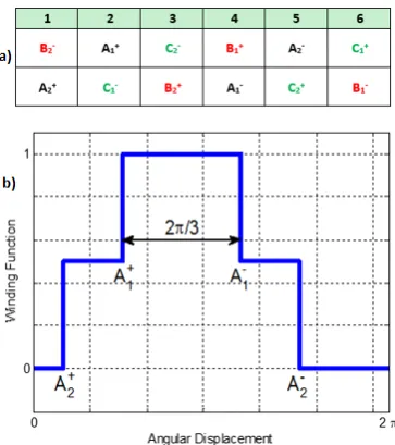
By limiting the considered case studies to three-phase, symmetrical windings embedded in the stator of classical SGs, the simplest configuration consists of a single-layer comprising 6p slots (where p is the number of pole pairs). Alternators with such winding structure were already in use by the late 1800s [25]. If a planar scheme is considered for the stator and if only one pole pair is taken into account (corresponding to 2π electrical radians), then the described winding can be illustrated as in the grid of Fig. 1a, where a distributed configuration is assumed. By using the winding function (WF) theory [20], one phase of the winding described above can be represented by the red function shown in Fig. 1c. Here, a full pitch winding is employed, meaning that the angle between the two sides of a coil (namely the winding pitch) is equal to the angle between the magnetic
Standard EN
50160
IEEE 519 (up to 69kV)
IEC 61000-2-2
IEC 61000-2-12 IEC 61000-3-6
Purpose limits limits compatibility levels planning levels indicative
Voltage level LV,
MV LV, MV LV, MV MV
h Harmonic voltage as a percentage of the fundamental [%]
3 5 3 5 4
5 6 3 6 5
7 5 3 5 4
9 1.5 3 1.5 1.2
11 3.5 3 3.5 3
13 3 3 3 2.5
15 0.5 3 0.4 0.3
17 2 3 2 1.7
19 1.5 3 1.76 1.5
21 0.5 3 0.3 0.2
23 1.5 3 1.41 1.2
25 1.5 3 1.27 1.09
25<h<40 - 3 2.27x(17/h)-0.27 1.9x(17/h)-0.2
3 poles (namely the pole pitch). This solution is the optimal
choice in terms of output maximization, as the highest magnitude of the fundamental component of a rectangular waveform is achieved when its trailing edge is at a distance equal to π radians from the leading edge, i.e. the case of the blue plot of Fig. 1c. One of the early winding methodologies was the introduction of concentrated windings. As shown in Fig. 1, if the winding of Fig. 1a is transformed into a concentrated configuration, then this would take the shape of a single layer with 6p slots but with the phases wound around a single stator tooth.
Fig. 1. Single-layer, 1-slot-per-pole-per-phase: a)
distributed winding planar scheme; b) concentrated winding planar scheme; c) comparison between the related winding functions
This winding structure allows for reduction of the end winding length (a key historic benefit) as well as improvement of the slot fill factor if modern automatic winding processes are used [26]. It is clear that the concentrated winding can be highly beneficial in relatively short machines with a low number of poles [27], [28], where the end windings’ length is comparable to that of the active sides of the coils. However, it is also true that the resulting WFs of each phase are modified and assume the shape of the red function of Fig. 1c, where it can be seen that the value of the fundamental is significantly reduced in comparison with the distributed winding of the same figure [21]. In the concentrated configuration described above, a short pitching is also applied to the winding, resulting in an angular distance between A+ and A- shorter than the pole pitch. In the specific case considered, a 1/3rd short pitching is obtained, allowing for attenuating specific harmonics in the induced EMF. Examples of machines employing winding of the type described above are provided in [21], [29].
Utilising a single winding layer limits the flexibility of short pitching to only the choice shown in Fig. 1. To circumvent this issue, a double layer winding can be used, where coils of different phases can be inserted into the same slot and thus an increased number of coils-per-phase can be achieved while keeping the same number of slots. Alternators built around this configuration were already present in the
early 1900s [25]. This last concept is shown in Fig. 2a, where a 2/3rd short pitching is employed. It is well-known that a 2/3rd pitch winding suppresses the 3rd harmonic (and its multiples) making it suitable for four-wire systems [22], [30]. It is also clear that the WF of Fig. 2b gives a more sinusoidally-distributed output if compared with the WF shown in Fig. 1b, however at the cost of decreasing the magnitude of its fundamental component.
Fig. 2. Double-layer, 2-slots-per-pole-per-phase distributed
winding: a) planar scheme; b) winding function
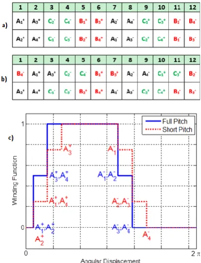
The winding distribution, consisting of splitting the armature coils over multiple slots (i.e. using an increased number of coils-per-phase), can be used to obtain a more sinusoidal output [7], [19], [21] and increased flexibility in terms of short pitching the windings. This concept can be observed in Fig. 3a, where 4p coils-per-phase are used with a full-pitch configuration, whereas Fig. 3b shows the same basic structure but with a 5/6th short pitching being applied to the winding. This 5/6th pitching is widely used in the field of electrical machines, as it reduces the 5th and the 7th harmonics and provides a lower THD for three-wire systems. Early literature from 1908 describes the benefits on the mechanical and manufacturing characteristics of 5/6th and other short pitched windings [23]. An example of this winding structure used in the field of SGs is given by [31]. A comparison between the WFs of these two windings can be seen in Fig. 3c, where it is again highlighted how the choice of the winding configuration is a trade-off study aimed at maximizing the output while complying with the power quality requirements. Although the winding solutions presented above represent only a portion of all the possible configurations currently used in electrical machines, they explain well how voltage waveform improvements were achieved in the history of utilization of these generators.
[image:3.595.336.518.152.357.2] [image:3.595.63.264.186.425.2]4 This also allows the design of the electrical machine to focus
on the interaction between different stator and rotor harmonics ks and kr. However, in absolute terms, the main operation of the machine has to comply with the relationship psks = prkr. Above all, fractional slot windings present the significant benefit of increasing the degrees of freedom in the choice of the number of slots and the pitching length as well as the opportunity to remove certain harmonics [21]. However, this particular winding configuration does produce high sub-harmonics, leading to a reduction of the overall efficiency [29]. More recently, multi-phase armature windings have been investigated for attenuating specific harmonics on the output of field-wound SGs [24]. Due to their inherent drawbacks such as lower power densities, these configurations are however limited to certain niche applications where redundancy under faults conditions is highly desirable [33].
Fig. 3. Double-layer, 4p slots-per-phase distributed winding: a) planar scheme of a full-pitched winding; b) planar scheme
of a short-pithed winding; c) comparison between the related winding functions
In non-salient machines, the field winding can be distributed into slots allowing a more sinusoidal airgap flux to be produced [21], [34]. This was identified as early as 1911 as a key advantage over salient pole machines [35]. Similarly if only two thirds of the rotor surface are slotted then the third harmonic and its multiples are cancelled [21].
Around the 1920s it was known that the connection of the windings at the terminals of a SG can cancel some harmonics. If a star connection is used then the third harmonic and its multiples are cancelled as long as the neutral is left ungrounded [36]. In a delta-connected generator the third harmonic current creates additional copper loss [36].
All the aspects discussed above, those related to the winding pitch and distribution as well as to the phase connections can be combined to produce an optimal WF which relates to the attenuation of harmonics in the machine EMF [37]. Tables of WFs for a number of example windings is given in [22].
2.2. Lamination/Core Geometry
[image:4.595.60.257.254.511.2]The geometry of the machine core packs dictates the shape of the flux linkage and therefore has a significant influence on the harmonics of the generated voltage waveform. The presence of slot openings on the armature core introduces high frequency harmonics (namely tooth ripple) on the air-gap flux. This phenomenon is well described from early engineering literature from the 1900s through to modern electrical machines textbooks [7], [25]. These harmonics introduced onto the machine EMF are at fundamental frequency sidebands around the slotting frequency [7]. The amplitude of these harmonics can vary with the loading and power factor [38]. However, as these parasitic components are caused by the “slotting” effect, they can be of paramount importance in large (i.e. high voltage) SGs, where an open-slot structure is typically employed [39]. One way to reduce the inherent ripples is that of providing the stator and/or the rotor of the machine with an appropriate angular offset along the axial length. This technique is known as skewing and has been implemented in SGs since the early 1900s. For historical and manufacturing reasons it has always been implemented as an angular offset equal to one slot pitch [21], [40]. However, this non-optimal methodology leaves lee-way for significant improvements which have recently received renewed interest in the field of SGs [41], although most efforts are focused mainly on other electrical machine families [42]. The effects of skewing on the no-load phase voltage waveform of a 400kVA SG is shown as an example in Fig. 4.
Fig. 4. Skewing: No-load waveform improvement
Another design aspect which can significantly affect the power quality in SGs is related to the shape of the salient poles. This technique has been implemented on early generators and was deeply investigated in a paper from 1924 [43], however it still represents a popular optimization design process, as demonstrated by more recent literature [44].
2.3. Inclusion of Damper Cage and its Optimal Design
[image:4.595.346.506.408.535.2]5 conditions, including the steady state. For the sake of this
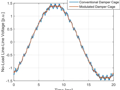
[image:5.595.58.266.466.622.2]study it is important to point out how the role of the damper cage also includes reducing harmonics in the air gap flux density, particularly those produced by the armature tooth ripple [45]. Several methods have been proposed in literature aiming at attenuating these parasitic effects through an optimised design of the damper cage [48]. Although, damper winding design has been traditionally performed by means of empirical and theoretical approaches [49], today modern finite-element (FE) and optimisation techniques are increasingly used to address the very complex phenomena related to the currents (and associated losses) induced in this winding and the associated harmonic distortion. In particular, the voltage THD can be improved by increasing the distance of the damping bars from the airgap (i.e. moving the bars along the radial direction) and by shifting the cage around the polar axes (i.e. moving the bars along the tangential direction) [39]. Complete and incomplete damper winding configurations have been shown to have a different impact on the voltage waveform quality, showing that complete end connections lead to higher slot ripple harmonic amplitudes [50]. However, all these designs usually come at the cost of inducing more elevated currents in the bars [51] and also the cost of modifying the generator behaviour during transients [52]. Improvement of the output voltage without compromising the bar losses can be achieved by providing the stator slots with high permeability wedges [53], as these reduce the slotting effects. This however leads to an increase of the slot leakage inductance of the machine. Recently, to counter the above challenges, a modulated damper winding (i.e. repositioning the bars) has been proposed in [31] with very positive results, which can be observed in Fig. 5. This shows the voltage waveform improvement obtained through the implementation of a modulated damper cage onto an existing 400kVA SG.
Fig. 5. Modulating the damper cage: No-load waveform
2.4. Final Considerations
This section has dealt with a survey of the design methods used in SGs for complying with output voltage THD requirements at the point of generation. The reviewed techniques therefore focus on the machine design choices which mostly affect the power quality of such classical machines, namely 1) the winding configuration, 2) the laminations/core geometry and 3) the damper cage design. These design methods are today enjoying a revived interest, mainly enabled by the advent of more powerful
computational resources aligned with accurate FE packages that permit detailed analysis. The main challenge is that these methods are disruptive and invasive. For generator manufacturers and machine suppliers, such machine design changes represent a considerable financial and manufacturing effort that from a business perspective is not always the most cost effective investment.
Alternative methods that can address power quality at a system level are those that include passive and active compensation techniques, usually achieved by including “extra” sub-systems at the machine’s terminals, usually taking the form of power filters. The ‘retro-fit’ and flexible nature of such methodologies has resulted in their popularity in the last decades, mainly driven by the ever-increasing advancements and availability of PE. These systems primarily focus on the reduction of harmonics in the load current waveform which would otherwise result in voltage distortion at the point where the load is coupled [54].
3. Harmonic Reduction for Distributed Generation and Renewables
In early power networks harmonics typically came from the generator or saturation of magnetic components such as transformers [55], [56]. These issues were mostly overcome by the machine design methods described in Section 2. With the advent of rectifier systems and PE converters the focus of harmonic mitigation research moved to the load. However, in recent years power networks have evolved to include distributed generation (DG) and renewable energy sources (RES). This, in parallel to the push towards energy trading and the concept of smart grids, has changed the traditional layout of the grid and placed generation at all voltage levels. RES are typically coupled to the grid through PE converters and as a result has renewed interest in harmonic reduction at the point of generation.
3.1. Grid Connection of Renewables
The use of PE converters to couple RES to the grid can result in resonance and harmonic instability, particularly when used in significant number [57], [58] or if the control system is not adequately tuned [59]. A framework for determining the maximum amount of DG resources in a system while maintaining harmonic limits is given in [60]. If properly controlled and interfaced to the distribution network, DG can improve both power quality and efficiency [61].
For renewable sources, the control scheme of the grid-connected converter plays a significant role in its harmonic effect on the supply and its tolerance to externally generated harmonics [62], [63]. Recent research has looked at new control and synchronisation methods to improve harmonic performance of grid connected renewables [64], [65].
6
Fig. 6. High level diagram of a UPQC [69]
3.2. Harmonic Mitigation in Microgrid Applications
A recent research focus has been on smart and microgrid networks where the majority of generation comes from renewable systems. In these cases, it is typical for a high proportion of loads to be PE to maximise efficiency and performance at the cost of harmonic distortion. The design of a hybrid harmonic filter, where a passive filtering element is combined with an active filter, specific to microgrid networks has been considered in [70].
Harmonic mitigation through power sharing has been a key focus of recent research as this is key for the operation of microgrids in islanded mode [71], [72]. Harmonic loads are shared between multiple generating units in which their interfacing PE acts as an active filter system, thereby improving overall voltage quality [73].
Microgrids are in some cases designed to power their loads during loss of the main grid supply (islanded operation). When the main grid is restored the microgrid must be able to resynchronise and connect. A strategy for performing this under phase unbalance and harmonic distortion is given in [74].
3.3. Energy Storage
RES provide intermittent power which can be a key issue in areas where they make up a significant proportion of the supply capability. One option to overcome this is that of grid connected energy storage, with commercial systems now becoming available [75]. These energy storage units are able to smooth power demand as well as providing ancillary functions such as harmonic mitigation and power factor correction [76], [77]. A key feature is that they can help stabilise weak grids where there is a large proportion of RES.
3.4. Final Considerations
RES and distributed generation are the latest challenges in harmonic mitigation and the key focus of recent research. New solutions based around existing knowledge of active filter systems are able to provide useful ancillary functions using the same hardware required to interface to the grid.
Microgrid networks provide a key challenge for harmonic mitigation, particularly where intermittent RES provide a significant proportion of power. New research into power sharing and energy storage is offering solutions to these challenges.
4. Conclusions
In the work outlined above, a comprehensive review of conventional power quality improvement measures at generation level has been given. The main focus is on THD improvements, where the main techniques and methodologies implemented onto electrical machines over the last century and a half have been described in sequence. Table II highlights some of the key THD achievements of different topologies and applications. An important aspect of the above work is that, although it has been presented with all the developments shown in chronological order, it is important to note that most of the described methodologies continue to evolve and thus continue to be valid considerations for new designs.
In recent times, the main focus of research has been on the load side system, in order to correct for the presence of harmonics from non-linear devices used in PE. However, with the advent of RES and more DG, the effects of these on harmonics have become a greater research focus. This will continue in the future as a larger proportion of energy is produced by renewable sources in an effort to meet climate change targets and reduce dependence on fossil fuels.
A major associated risk of moving to multiple low power generating systems, in many cases optimised for low cost and ease of manufacture, is that of damaging connected equipment and/or destabilizing the existing supply through reduced power quality and harmonic interaction between large numbers of similar systems (as is already being seen in wind power installations [58]). Thus in the near future, concentrated efforts aimed at addressing these challenges are required.
A comprehensive review of the methods employed for mitigating harmonic distortions in electrical generation
Table II Harmonic mitigation topologies and applications
Application Year THD Topology
Early alternators by Ganz & Co, and Siemens & Halske [16]
Late 1800s >12% Single layer, 1 slot-per-pole-per-phase, full-pitch,
skew-less
6MVA, electric generator [17] Early 1900s >10% &
<12%
Single layer, n slots-per-pole-per-phase, full-pitch, skew-less, delta connected
Medium to large rated SGs for power generation [35]
1950s (still produced)
>5% Double layer, short-pitched distributed winding,
skew-less Medium to large rated SGs for standalone
generation [90]
2014 ~2.5% Double layer, short-pitched distributed winding,
skew-less, “shifted” damper cage Medium to large rated SGs for standalone
generation [28]
2017 ~2.5% Double layer, short-pitched winding, skew-less,
modulated damper cage
Small to medium rated SGs [27], [40] 1980s (still
produced)
[image:6.595.52.551.630.772.2]7 systems has been dealt with in this paper. In particular, the
main prominent aspects considered include
Synchronous generator design with special considerations on 1) Winding configurations, 2) lamination and core geometries and 3) Damper cage design.
Distributed generation with special considerations on 1) Grid interfacing of RES, 2) Microgrid networks and 3) Energy storage systems.
In order to conclude this review paper, a summary of the machine design methods of harmonic mitigation was presented in Table II, which highlights the major applications and topologies developed from late 1800 to present day. Even considering the extensive existing development in the context of power quality improvements, new and innovative techniques [30], [31] are continuing to be investigated and proposed. In particular [30] shows significant potential in improving the voltage THD of a 48.5kVA SG, used as vessel to prove the proposed approach. This methods allows the power density of the machine to be improved making it particularly suited for distributed generation systems which are an ever increasing component of power networks.
5. References
[1] M. H. Bollen, ‘Overview of Power Quality and Power Quality Standards’, in Understanding Power Quality Problems:Voltage Sags and Interruptions, Wiley-IEEE Press, 2000, pp. 1–34.
[2] Leonard L. Grigsby, The Electric Power Engineering Handbook. CRC Press, 2000.
[3] N. Jenkins and et al., Embedded Generation. Institution of Engineering and Technology, 2000.
[4] S. M. Halpin, ‘Harmonics in Power Systems’, in
Electric Power Generation, Transmission, and Distribution, Third Edition, 5 vols, CRC Press, 2012, pp. 1–10.
[5] IEEE, ‘IEEE Recommended Practices and Requirements for Harmonic Control in Electrical Power Systems’, 1993.
[6] C. Debruyne, J. Desmet, J. Rens, and J. D. Kock, ‘The effect of a reduced power quality on the energy efficiency of stand-alone generator systems’, presented at the 2015 IEEE International Electric Machines & Drives Conference (IEMDC), 2015, pp. 1902–1909. [7] J. C. Das, Power System Analysis: Short-Circuit Load
Flow and Harmonics. Taylor & Francis, 2002. [8] Load Characteristics Task Force and Effects of
Harmonics Task Force, ‘The Effects of Power System Harmonics on Power System Equipment and Loads’,
IEEE Trans. Power Appar. Syst., vol. PAS-104, no. 9, pp. 2555–2563, Sep. 1985.
[9] R. C. Dugan, S. Santoso, M. F. McGranaghan, and H. W. Beaty, Electrical Power Systems Quality. McGraw Hill Professional, 2002.
[10] R. B. Robinson, ‘Harmonics in a.c. rotating machines’,
Proc. IEE - Part C Monogr., vol. 109, no. 16, pp. 380– 387, Sep. 1962.
[11] H. C. Lin, ‘Identification of interharmonics using disperse energy distribution algorithm for flicker troubleshooting’, IET Sci. Meas. Technol., vol. 10, no. 7, pp. 786–794, 2016.
[12] M. Dalali and A. Jalilian, ‘Indices for measurement of harmonic distortion in power systems according to IEC 61000-4-7 standard’, Transm. Distrib. IET Gener., vol. 9, no. 14, pp. 1903–1912, 2015.
[13] V. Ćuk, J. F. G. Cobben, P. F. Ribeiro, and W. L. Kling, ‘A review of international limits for harmonic voltages and currents in public networks’, presented at the 2014 16th International Conference on Harmonics and Quality of Power (ICHQP), 2014, pp. 621–625. [14] P. M. Lincoln, ‘Wave Form Distortions and their
Effects on Electrical Apparatus’, Trans. Am. Inst. Electr. Eng., vol. XXXII, no. 1, pp. 765–774, Jan. 1913. [15] IEEE, ‘IEEE Recommended Practice and
Requirements for Harmonic Control in Electric Power Systems’, 2014.
[16] A. E. Emanuel, ‘Harmonics in the early years of electrical engineering: a brief review of events, people and documents’, presented at the Ninth International Conference on Harmonics and Quality of Power. Proceedings (Cat. No.00EX441), 2000, vol. 1, pp. 1–7 vol.1.
[17] E. L. Owen, ‘A history of harmonics in power systems’,
IEEE Ind. Appl. Mag., vol. 4, no. 1, pp. 6–12, Jan. 1998. [18] S. P. Thompson, Polyphase Electric Currents and
Alternate-current Motors. Spon & Chamberlain, 1900. [19] W. J. Foster, ‘Potential Waves of Alternating-Current Generators’, Trans. Am. Inst. Electr. Eng., vol. XXXII, no. 1, pp. 749–764, 1913.
[20] A. Tessarolo, ‘Accurate Computation of Multiphase Synchronous Machine Inductances Based on Winding Function Theory’, IEEE Trans. Energy Convers., vol. 27, no. 4, pp. 895–904, Dec. 2012.
[21] J. Pyrhonen, T. Jokinen, and V. Hrabovcova, Design of Rotating Electrical Machines. John Wiley & Sons, 2009.
[22] T. A. Lipo, ‘Winding Distribution in an Ideal Machine’, in Analysis of Synchronous Machines, Second Edition, 0 vols, CRC Press, 2012, pp. 1–76.
[23] J. Bache-Wiig, ‘Application of fractional pitch windings to alternating-current generators’, Proc. Am. Inst. Electr. Eng., vol. 27, no. 5, pp. 657–665, 1908. [24] S. Jordan, C. D. Manolopoulos, and J. M. Apsley,
‘Winding Configurations for Five-Phase Synchronous Generators With Diode Rectifiers’, IEEE Trans. Ind. Electron., vol. 63, no. 1, pp. 517–525, Jan. 2016. [25] C. A. Adams, ‘Electromotive force wave-shape in
alternators’, Proc. Am. Inst. Electr. Eng., vol. 28, no. 7, pp. 791–814, 1909.
[26] D. Nguyen, R. Dutta, M. F. Rahman, and J. E. Fletcher, ‘Performance of a Sensorless Controlled Concentrated-Wound Interior Permanent-Magnet Synchronous Machine at Low and Zero Speed’, IEEE Trans. Ind. Electron., vol. 63, no. 4, pp. 2016–2026, Apr. 2016. [27] B. Xia, J. X. Shen, P. C. K. Luk, and W. Fei,
‘Comparative Study of Air-Cored Axial-Flux Permanent-Magnet Machines With Different Stator Winding Configurations’, IEEE Trans. Ind. Electron., vol. 62, no. 2, pp. 846–856, Feb. 2015.
8 [29] P. B. Reddy, K. K. Huh, and A. M. EL-Refaie,
‘Generalized Approach of Stator Shifting in Interior Permanent-Magnet Machines Equipped With Fractional-Slot Concentrated Windings’, IEEE Trans. Ind. Electron., vol. 61, no. 9, pp. 5035–5046, Sep. 2014. [30] D. Fallows, S. Nuzzo, A. Costabeber, and M. Galea,
‘Power Quality Improvement by Pre-Computed Modulated Field Current for Synchronous Generators’, in Proceeding of Workshop on Electrical Machines Design, Control and Diagnosis (WEMDCD), Nottingham, UK, 2017.
[31] S. Nuzzo, M. DEgano, M. Galea, C. Gerada, N. Brown, and D. Gerada, ‘Improved Damper Cage Design for Salient-Pole Synchronous Generators’, IEEE Trans. Ind. Electron., vol. PP, no. 99, pp. 1–1, 2016.
[32] M. Galea, C. Gerada, T. Raminosoa, and P. Wheeler, ‘Design of a high force density tubular permanent magnet motor’, in The XIX International Conference on Electrical Machines - ICEM 2010, 2010, pp. 1–6. [33] M. J. Duran and F. Barrero, ‘Recent Advances in the
Design, Modeling, and Control of Multiphase Machines - Part II’, IEEE Trans. Ind. Electron., vol. 63, no. 1, pp. 459–468, Jan. 2016.
[34] I. Boldea, ‘Large and Medium Power Synchronous Generators’, in Synchronous Generators, 2 vols, CRC Press, 2005, pp. 4-1-4–56.
[35] S. P. Smith, ‘The non-salient pole turbo-alternator and its characteristics’, Electr. Eng. J. Inst. Of, vol. 47, no. 209, pp. 562–601, 1911.
[36] T. S. Eden, ‘Relative merits of Y and delta connection for alternators’, Proc. Am. Inst. Electr. Eng., vol. 33, no. 5, pp. 791–794, 1914.
[37] L. V. Bewley, ‘Induced Voltage of Electrical Machines’, Trans. Am. Inst. Electr. Eng., vol. 49, no. 2, pp. 456–466, 1930.
[38] G. W. Worrall, ‘Magnetic oscillations in alternators’,
Electr. Eng. J. Inst. Of, vol. 39, no. 184, pp. 206–220, 1907.
[39] S. Nuzzo, M. Galea, C. Gerada, D. Gerada, A. Mebarki, and N. L. Brown, ‘Damper cage loss reduction and no-load voltage THD improvements in salient-pole synchronous generators’, in 8th IET International Conference on Power Electronics, Machines and Drives (PEMD 2016), 2016, pp. 1–7.
[40] M. P. Kostenko and L. M. Piotrovskiĭ, Electrical Machines. Creset, 1968.
[41] S. Nuzzo, M. Galea, C. Gerada, and N. Brown, ‘A fast method for Modelling Skew and its Effects in Salient-Pole Synchronous Generators’, IEEE Trans. Ind. Electron., vol. PP, no. 99, pp. 1–1, 2017.
[42] M. Aydin and M. Gulec, ‘Reduction of Cogging Torque in Double-Rotor Axial-Flux Permanent-Magnet Disk Motors: A Review of Cost-Effective Magnet-Skewing Techniques With Experimental Verification’, IEEE Trans. Ind. Electron., vol. 61, no. 9, pp. 5025–5034, Sep. 2014.
[43] B. Hague, ‘The shape of pole-shoe required to produce a sinusoidal distribution of air-gap flux density’, J. Inst. Electr. Eng., vol. 62, no. 335, pp. 921–929, Nov. 1924. [44] Y. Wang et al., ‘Sensitivity Analysis for Performance
and Power Density Improvements in Salient-Pole Synchronous Generators’, in Proceeding of Workshop
on Electrical Machines Design, Control and Diagnosis (WEMDCD), Nottingham, UK, 2017.
[45] E. W. Kimbark, Power System Stability. John Wiley & Sons, 1995.
[46] C. F. Wagner, ‘Damper Windings for Water-Wheel Generators’, Trans. Am. Inst. Electr. Eng., vol. 50, no. 1, pp. 140–151, 1931.
[47] R. B. George and B. B. Bessesen, ‘Generator Damper windings at Wilson Dam’, Electr. Eng., vol. 58, no. 4, pp. 166–172, 1939.
[48] D. w Zhang, Y. j Peng, and Z. n Fan, ‘No-Load Voltage Waveform Optimization and Rotor Heat Reduction of Tubular Hydro-Generator’, in 2012 Sixth International Conference on Electromagnetic Field Problems and Applications, 2012, pp. 1–4.
[49] M. M. Liwschitz-Garik, ‘Harmonics of the Salient-Pole Synchronous Machine and Their Effects Part III. Differential Leakage of the Damper Winding with Respect to the Main Wave. Current Distribution in the Damper Bars’, Trans. Am. Inst. Electr. Eng. Part III Power Appar. Syst., vol. 77, no. 3, pp. 462–469, Apr. 1958.
[50] M. Wallin, M. Ranlóf, and U. Lundin, ‘Design and construction of a synchronous generator test setup’, in
The XIX International Conference on Electrical Machines - ICEM 2010, 2010, pp. 1–5.
[51] A. Tessarolo, C. Bassi, and D. Giulivo, ‘Time-Stepping Finite-Element Analysis of a 14-MVA Salient-Pole Shipboard Alternator for Different Damper Winding Design Solutions’, IEEE Trans. Ind. Electron., vol. 59, no. 6, pp. 2524–2535, Jun. 2012.
[52] G. Traxler-Samek, R. Zickermann, and A. Schwery, ‘Cooling Airflow, Losses, and Temperatures in Large Air-Cooled Synchronous Machines’, IEEE Trans. Ind. Electron., vol. 57, no. 1, pp. 172–180, Jan. 2010. [53] S. Wang, Z. Zhao, L. Yuan, and B. Wang,
‘Investigation and analysis of the influence of magnetic wedges on high voltage motors performance’, in 2008 IEEE Vehicle Power and Propulsion Conference, 2008, pp. 1–6.
[54] American Bureau of Shipping, Guidance Notes on Control of Harmonics in Electrical Power Systems. Houston, USA: American Bureau of Shipping, 2006. [55] G. Faccioli, ‘Triple harmonics in transformers’, J. Am.
Inst. Electr. Eng., vol. 41, no. 5, pp. 351–359, May 1922.
[56] O. G. C. Dahl, ‘Transformer Harmonics and Their Distribution’, Trans. Am. Inst. Electr. Eng., vol. XLIV, pp. 792–805, Jan. 1925.
[57] C. Yoon, H. Bai, R. N. Beres, X. Wang, C. L. Bak, and F. Blaabjerg, ‘Harmonic Stability Assessment for Multiparalleled, Grid-Connected Inverters’, IEEE Trans. Sustain. Energy, vol. 7, no. 4, pp. 1388–1397, Oct. 2016.
[58] E. Ebrahimzadeh, F. Blaabjerg, X. Wang, and C. L. Bak, ‘Harmonic Stability and Resonance Analysis in Large PMSG-Based Wind Power Plants’, IEEE Trans. Sustain. Energy, vol. 9, no. 1, pp. 12–23, Jan. 2018. [59] V. Salis, A. Costabeber, S. M. Cox, P. Zanchetta, and
9 [60] V. R. Pandi, H. H. Zeineldin, and W. Xiao,
‘Determining Optimal Location and Size of Distributed Generation Resources Considering Harmonic and Protection Coordination Limits’, IEEE Trans. Power Syst., vol. 28, no. 2, pp. 1245–1254, May 2013. [61] J. He, Y. W. Li, and M. S. Munir, ‘A Flexible
Harmonic Control Approach Through Voltage-Controlled DG-Grid Interfacing Converters’, IEEE Trans. Ind. Electron., vol. 59, no. 1, pp. 444–455, Jan. 2012.
[62] J. He, Y. W. Li, X. Wang, and F. Blaabjerg, ‘An improved current control scheme for grid-connected DG unit based distribution system harmonic compensation’, in 2013 Twenty-Eighth Annual IEEE Applied Power Electronics Conference and Exposition (APEC), 2013, pp. 986–991.
[63] X. Liang and C. Andalib-Bin-Karim, ‘Harmonic mitigation through advanced control methods for grid-connected renewable energy sources’, in 2017 IEEE Industry Applications Society Annual Meeting, 2017, pp. 1–12.
[64] U. K. Kalla, B. Singh, and S. S. Murthy, ‘Enhanced Power Generation From Two-Winding Single-Phase SEIG Using LMDT-Based Decoupled Voltage and Frequency Control’, IEEE Trans. Ind. Electron., vol. 62, no. 11, pp. 6934–6943, Nov. 2015.
[65] L. Hadjidemetriou, E. Kyriakides, and F. Blaabjerg, ‘A Robust Synchronization to Enhance the Power Quality of Renewable Energy Systems’, IEEE Trans. Ind. Electron., vol. 62, no. 8, pp. 4858–4868, Aug. 2015. [66] D. I. Brandao, H. K. M. Paredes, A. Costabeber, and F.
P. Marafão, ‘Flexible active compensation based on load conformity factors applied to non-sinusoidal and asymmetrical voltage conditions’, IET Power Electron., vol. 9, no. 2, pp. 356–364, 2016.
[67] D. Ahmadi and J. Wang, ‘Online Selective Harmonic Compensation and Power Generation With Distributed Energy Resources’, IEEE Trans. Power Electron., vol. 29, no. 7, pp. 3738–3747, Jul. 2014.
[68] M. Prodanovic, K. D. Brabandere, J. V. D. Keybus, T. Green, and J. Driesen, ‘Harmonic and reactive power compensation as ancillary services in inverter-based distributed generation’, Transm. Distrib. IET Gener., vol. 1, no. 3, pp. 432–438, May 2007.
[69] S. K. Khadem, M. Basu, and M. F. Conlon, ‘Integration of UPQC for Power Quality improvement in distributed generation network - a review’, presented at the 2011 2nd IEEE PES International Conference and Exhibition on Innovative Smart Grid Technologies, 2011, pp. 1–5.
[70] D. Li and Z. Q. Zhu, ‘A Novel Integrated Power Quality Controller for Microgrid’, IEEE Trans. Ind. Electron., vol. 62, no. 5, pp. 2848–2858, May 2015. [71] J. He, Y. W. Li, and F. Blaabjerg, ‘An Enhanced
Islanding Microgrid Reactive Power, Imbalance Power, and Harmonic Power Sharing Scheme’, IEEE Trans. Power Electron., vol. 30, no. 6, pp. 3389–3401, Jun. 2015.
[72] P. Sreekumar and V. Khadkikar, ‘Direct Control of the Inverter Impedance to Achieve Controllable Harmonic Sharing in the Islanded Microgrid’, IEEE Trans. Ind. Electron., vol. 64, no. 1, pp. 827–837, Jan. 2017.
[73] Q. Liu, Y. Tao, X. Liu, Y. Deng, and X. He, ‘Voltage unbalance and harmonics compensation for islanded microgrid inverters’, IET Power Electron., vol. 7, no. 5, pp. 1055–1063, May 2014.
[74] F. Tang, J. M. Guerrero, J. C. Vasquez, D. Wu, and L. Meng, ‘Distributed Active Synchronization Strategy for Microgrid Seamless Reconnection to the Grid Under Unbalance and Harmonic Distortion’, IEEE Trans. Smart Grid, vol. 6, no. 6, pp. 2757–2769, Nov. 2015.
[75] ‘Tesla Powerpack’. [Online]. Available: https://www.tesla.com/powerpack. [Accessed: 02-Mar-2018].
[76] S. Yan, S. C. Tan, C. K. Lee, B. Chaudhuri, and S. Y. R. Hui, ‘Use of Smart Loads for Power Quality Improvement’, IEEE J. Emerg. Sel. Top. Power Electron., vol. 5, no. 1, pp. 504–512, Mar. 2017. [77] M. Niroomand, T. Feldmann, and E. Bollin,
‘High-performance control system for grid-tied ESSs’,
Transm. Distrib. IET Gener., vol. 11, no. 8, pp. 2138– 2145, 2017.
![Table I Limits and levels imposed on odd harmonics [13]](https://thumb-us.123doks.com/thumbv2/123dok_us/8555848.364166/2.595.42.286.432.672/table-limits-and-levels-imposed-on-odd-harmonics.webp)
![Fig. 6. High level diagram of a UPQC [69]](https://thumb-us.123doks.com/thumbv2/123dok_us/8555848.364166/6.595.52.551.630.772/fig-high-level-diagram-upqc.webp)
