This is a repository copy of Repressing oxidative wear within Si doped DLCs.
White Rose Research Online URL for this paper:
http://eprints.whiterose.ac.uk/83845/
Version: Accepted Version
Article:
Lanigan, JL, Wang, C, Morina, A et al. (1 more author) (2016) Repressing oxidative wear
within Si doped DLCs. Tribology International, 93 (B). pp. 651-659. ISSN 0301-679X
https://doi.org/10.1016/j.triboint.2014.11.004
© 2014, Elsevier. Licensed under the Creative Commons
Attribution-NonCommercial-NoDerivatives 4.0 International
http://creativecommons.org/licenses/by-nc-nd/4.0/
eprints@whiterose.ac.uk https://eprints.whiterose.ac.uk/ Reuse
Unless indicated otherwise, fulltext items are protected by copyright with all rights reserved. The copyright exception in section 29 of the Copyright, Designs and Patents Act 1988 allows the making of a single copy solely for the purpose of non-commercial research or private study within the limits of fair dealing. The publisher or other rights-holder may allow further reproduction and re-use of this version - refer to the White Rose Research Online record for this item. Where records identify the publisher as the copyright holder, users can verify any specific terms of use on the publisher’s website.
Takedown
If you consider content in White Rose Research Online to be in breach of UK law, please notify us by
1
Repressing oxidative wear within Si doped DLCs
J. L. Lanigan*, C. Wang, A. Morina, A. Neville*Corresponding author: cm06jl@leeds.ac.uk Abstract
Diamond-like Carbon coatings are well-known for their excellent wear and friction reducing properties. Novel DLCs are constantly being developed that further these beneficial characteristics; this is often achieved by incorporating a dopant into the microstructure of the DLC. One dopant that is widely used currently in commercial settings, including F1 car engines, is silicon. Si doping can be, to some extent, regarded as a double-edged sword. This is because, whilst it has been reported as being able to reduce friction in certain environments, this usually comes at the cost of far higher wear than the corresponding un-doped DLC. The fundamental aspects of Si-DLC’s friction and wear properties are explored herein with the goal of optimising the coating using fundamental tribochemical knowledge.
Keywords: Lubricated wear; Surface chemical analysis; Diamond-like coating; Tribochemistry 1. Introduction
Many dopants have been used to influence DLCs coating properties; notable dopants include the metalloid Si and non-metal F, respectively. Metallic dopants are also often used including Ti and W, often with the motivation of either altering the hardness or increasing the surface activity to oil additives (1). There are various reasons for incorporating dopants into the DLCs microstructure, including; improving hardness, altering carbon bonding within the DLC and increasing
coating/substrate adhesion. Si doping is generating much interest in the field of DLC research as there are many claims that its inclusion can positively affect the friction coefficient of the coating (2-6). Si-doped DLCs are also beneficial in that they can both alter the sp2/sp3 ratio of the coating and increase adhesion of the coating to the substrate (6, 7).
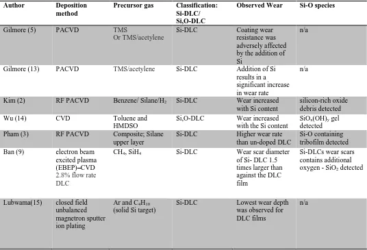
The literature on non-lubricated Si-DLC contacts suggests that they have a lower friction coefficient than non-doped DLCs. Lubricated test results are not as favourable (1, 2, 8-10). In the vast majority of cases (Table 1), Si-DLC is reported to increase the overall wear of the coating when compared to a similar non-doped (a-C:H) DLCs. This effect is seen in many different types of Si-DLCs regardless of the source gases, % Si content or inclusion of oxygen. The mechanism of accelerated wear within Si-DLCs was explored extensively with XPS and ToF-SIMS in previous work (11). In order to stabilise Si-DLCs with respect to wear the coating needs to have greater oxidative stability as silicon within a carbon matrix has a propensity to oxidise as there is a strong thermodynamic driving force for this reaction (12). Whether the Si-DLC is produced from solely a silane or a combination of hydrocarbon and siloxane, the wear is typically far higher for the Si-DLC, or Si,O –DLC than that of the non-doped DLC. To fully explore the wear behaviour of Si-DLCs a novel doped DLC was produced and tested in formulated oil. Advanced surface analysis techniques were then conducted to explore the
2 Table 1 Literature showing the Si content's effect on the DLCs
2. Experimental 2.1 Tribological test
A reciprocating pin-on-plate TE77 tribometer was employed for the tribological testing (16). The conditions chosen were employed so as to emulate the camshaft contact pressure profile. A load of 25 N was employed to give a maximum Hertzian pressure of 0.81 GPa. Oil temperature was maintained at 100°C with use of a thermocouple. Frequency of reciprocation was set to 25 Hz with a stroke length of 5 mm and a sliding speed of 0.2 m/s. The volume of oil used in the experiments was 4 ml. Each coating was tested three times to ensure accuracy in results, the error shown is the standard deviation from the average.
2.2 Materials
Steel plates on which the DLC coatings were deposited had dimensions and materials specifications of: AISI 52100 Steel, 7x7x3 (length, width and depth respectively) mm, hardness of 58-60 HRC with an Ra of 0.1 – 0.2 m. The counter body employed was a domed 10 mm pin of BS1452 cast iron with hardness of 44 – 46 HRC, Ra of 0.2 – 0.3 m.
2.3 Lubricant Author Deposition
method
Precursor gas Classification: Si-DLC/ Si,O-DLC
Observed Wear Si-O species
Gilmore (5) PACVD TMS
Or TMS/acetylene
Si-DLC Coating wear resistance was adversely affected by the addition of Si
n/a
Gilmore (13) PACVD TMS/acetylene Si-DLC Addition of Si results in a
significant increase in wear rate
n/a
Kim (2) RF PACVD Benzene/ Silane/H2 Si-DLC Wear increased
with Si content
silicon-rich oxide debris detected
Wu (14) CVD Toluene and
HMDSO
Si,O-DLC Wear increased with the Si content
SiOx(OH)y gel
detected Pham (3) RF PACVD Composite; Silane
upper layer
Si-DLC Higher wear rate than un-doped DLC
Si-O containing tribofilm detected
Ban (9) electron beam excited plasma (EBEP)–CVD
2.8% flow rate DLC
CH4, SiH4 Si-DLC Wear scar diameter
of Si- DLC 1.5 times larger than against the DLC film
Si-DLCs wear scars contains additional oxygen - SiO2 detected
Lubwama(15) closed field unbalanced magnetron sputter ion plating
Ar and C4H10
(solid Si target)
Si-DLC Lowest wear depth was observed for DLC films
3
The lubricant employed was a low additive oil, blended to contain viscosity modifiers and detergents. Anti-oxidant additives (including ZDDP which is well-known to behave as an anti-oxidant) were purposefully excluded from the lubricant blend due to the key role of oxide species play when observing Si- DLCs. The viscosity of the lubricant at 100° C was 12.31 cSt.
2.4 Coatings
The DLC coating used in this project included two commercially available DLCs, as well as a novel DLC. All were produced using the Plasma Assisted Chemical Vapour Deposition (PACVD)
technique. The coatings are produced using lower temperature plasma; the substrate is negatively biased by 500 V with the chamber acting as the electrode. A hot cathode auxiliary system is also employed to enhance plasma generation. The process typically takes place at 10-3 mbar. The coatings can be viewed as multi-layered as there are interlayers employed to improve coating adhesion to the substrate. The substrate is first cleaned with argon ion etching before any deposition commences. Then a titanium layer is deposited, followed by a silicon based interlayer. After interlayer deposition the bulk DLC is deposited. This layer is made from a precursor that is highly sp2 hybridised. The silicon containing component cannot be revealed due to commercial sensitivity. The fluorine component is introduced into the DLC exclusively by use of fluoroform.
The specific protocol for production of a composite DLC (Error! Reference source not found.) with a Si,O,F doped top-layer, is as follows:
Layer 1 : Si,O doped DLC (undisclosed organometallic precursor material)
Layer 2 : Short transition of a mix of (organometallic precursor material) + CxHy + Argon
Layer 3 : Additional Si,O doped DLC
Layer 4: (top surface) Combination of the organometallic precursor and Fluoroform. Followed by venting with Fluoroform.
The doped coatings were analysed by XPS to ascertain the % atomic dopant levels. XPS analysis confirms that the Si,O doped sample contains 16.9 ± 4.11 % atomic concentration of Si and 5.75% ± 0.60 of O. The Si,O,F doped sample contains 3.6 ± 0.2% atomic concentration of Si, 13.09 ± 1.7 % of oxygen and 1.1 ± 0.1 % F. It is noted that the elemental composition of the two DLCs is different. Due to the nature of one DLC being a commercial sample and the difficulty of incorporating three dopants into the DLCs, this could not easily be altered. The potential affect this could have upon results is discussed later.
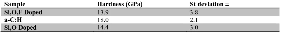
[image:4.595.65.531.647.702.2]Each coating’s hardness prior to wear testing is given below (Table 2): Table 2 Coating hardness values as obtained by nano indentation testing
Sample Hardness (GPa) St deviation ±
Si,O,F Doped 13.9 3.8
a-C:H 18.0 2.1
Si,O Doped 14.4 3.0
4
To assess whether including Si and F affects the coating in the same manner that F-doping is known to, by altering the surface wettability, water contact angles of the novel and reference coatings have been obtained (17). The instrument used to measure water contact angles in this case was a
‘FTA4000’ video drop shape analysis system (18). To ensure accurate results, ‘Mili-Q’ high purity, deionised water is used this is pumped via a ‘Nano Dispense’ electronic pump to aid accurate
dispensing. Two microscopes are fitted to the equipment: an analytical microscope to capture the drop shape image and a look-down alignment microscope. The analytical microscope has a zoomed
horizontal field of view from 2 mm down to 200 µm. The viewing angle is adjustable to 0° or 3° with respect to the specimen surface. The apparatus is housed within a dark room and is enclosed to protect from local fluctuations in heat. The stage is back-lit by a high intensity LED source. Image capturing is dynamic with variable resolutions. The software associated with the machine provides static contact angle analysis from the images captured. The contact angle of three water droplets were analysed for each sample, ensuring accuracy and allowing for standard deviation to be calculated.
2.6 X-ray Photoelectron Spectroscopy (XPS)
In order to fully ascertain the wear and friction relationship observed advanced surface analysis techniques were employed to examine both the plate and the pin of the novel coating. XPS analysis of the Si,O,F doped plate and counter body were conducted to assess surface reactions that could be affecting wear. XPS was carried out at the NEXUS XPS facility, Newcastle, using a VG ESCALAB 250 X-ray Photoelectron Spectrometer which uses monochromatized X-rays from an aluminium K alpha source. The system also employs high transmission electron optics and a multi-channel detector. An approximate area of 500 m2 was analysed in the worn area. XPS is surface specific in that it can only penetrate the upper few nanometres of the sample. A short survey scan was carried out at first to determine which elements were present. Longer scans of the selected peaks were carried out to fully resolve any peaks present. CasaXPS software was used to analyse the data. XPS spectra were
calibrated using the main C1s peak component, which is well characterised in the literature. Works in the literature specify spectra of DLC films should be calibrated to the hydrocarbon (CHx) peak at 284.4 eV (19-22). Calibration shifted the spectrum by 1.2 eV, correcting for charging issues.
CasaXPS was also used for curve fitting procedures on the peaks obtained using the Shirley algorithm to construct a background. Peak area and full-width at half-maximum (FWHM) were constrained in order to obtain information with the most appropriate chemistry associated with the system. The value of FWHM of the XPS peaks herein is a convolution of the analyser resolution and of the natural FWHM of the peaks (23-25). Where standard deviations are given, averages were obtained by measuring the sample coating in three separate areas to give accurate values.
2.7 Time-of-Flight Secondary Ions Mass Spectrometry (ToF-SIMS)
ToF-SIMS was employed to identify any local variations in the worn area as well as to fully chemically characterise any novel, localised species that could be forming. The SIMS system used employs a primary ion beam source of bismuth, in the form of a liquid metal ion gun. The primary ions are fired at the worn area and impact on the surface provokes ejection of secondary ions from the surface of interest which are allowed a brief flight time before encountering a mass detector. A cluster ion beam of Bi3+ was used with an energy of 2 KeV. The target current was 1 Pico amp (or within the range 0.1 - 3.0 Pico amps), from the flood gun to compensate for charge build up. Spectra obtained were analysed using ION-TOF software. Individual spectra were calibrated to the H, C, CH, O and OH signals for the negative spectra and a deviation limit of 70 ppm was used to ensure
5 2.8 Nano hardness measurements
Surface hardness values were obtained using a Nanotest™ Nano indenter produced by Micro Materials Ltd Wrexham, UK. The test apparatus is in an enclosed, temperature regulated box to ensure no fluctuations due to heating or cooling processes. The Nanotest platform software suite and micro capture camera were used to obtain, analyse and interpret the data. A diamond tipped probe was employed for testing and all samples were mounted to the holder using a high strength adhesive. The maximum penetration depth employed was 51.3 nm or a penetration depth of 4% into the coating. Eight measurements were made either within or outside of the worn area to allow for good levels of accuracy, standard deviation is provided with the data.
2.9 Contact Profilometry
Contact profilometry measurements were obtained using a Taylor Hobson Form Taly surf 120 L. The system employs a diamond tipped stylus of 2 m and is able to resolve to 10 nm. Prior to
measurements the stylus is calibrated with a standard to ensure accuracy. Measurements were interpreted using the ‘ ltra 5.23.87’ software suite to produce visual images and obtain numerical data. Four data sets were obtained for each measurement and these values were averaged. The
standard deviation of each set was found. Worn volumes can be calculated from profilometry data and this then can be converted into a dimensional wear coefficient. Profilometry data yields wear scar width and depth measurements, length of the wear scar was already known as it is part of the experimental setup. This allows calculation of worn volumes. Dimensional wear coefficients values are useful as they allow comparisons of wear performance over different testing parameters. The dimensional wear coefficient is the worn volume (m3) divided by the sliding distance (m) multiplied by the unit of load (N).
3 Results and analysis 3.1 Surface wettability
Water contact angle measurements were obtained for the three coatings examined. The novel Si,O,F coating and the a-C:H coating show no significant difference in their water contact angles (87.67 ± 1.25 ° and 89.60 ± 4.81 °, respectively). However, the Si,O-DLC coating shows enhanced wettability (70.07 ± 4.70 °). As such, contact angle results indicate that the inclusion of both F and Si
simultaneously does not affect the surface wettability when compared with non-doped a-C:H DLC. 3.2 Friction performance
6
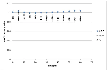
Figure 1 Overall friction profiles of novel DLCs in oil, average of 3 tests with error bars showing standard deviation.
3.3 Wear performance
3.3.1 Optical microscope images of wear scars
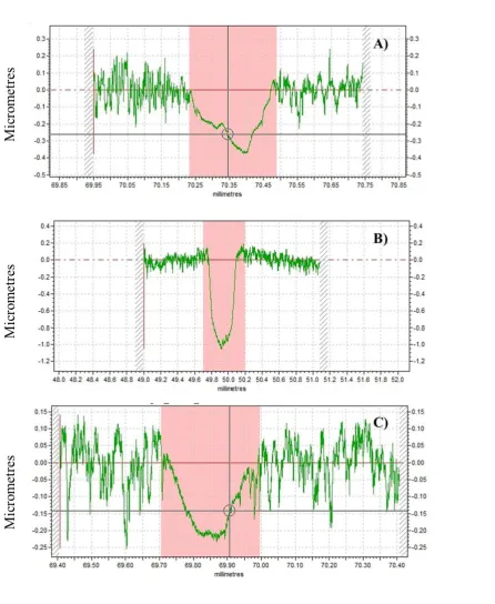
Optical microscopy (Figure 2) identifies the nature of the wear within the scars on the plate. For the Si,O,F doped DLC the worn area undergoes only very-minor polishing, made clear by the
preservation of the scratches in the DLC surface; these are artefacts from the steel substrate. The a-C:H sample shows more severe wear than the Si,O,F doped sample, there is clear evidence of
polishing wear on the plate. The Si,O-DLC shows the highest level of wear with the widest wear track and sections of steel substrate being exposed on either end of the wear scar.
Figure 2 Optical microscopy imaging of worn area (a) a-C:H, (b) Si,O-DLC, (c) Si,O,F-DLC. 0
0.02 0.04 0.06 0.08 0.1 0.12
0 10 20 30 40 50 60 70
C
o
e
ff
ic
ie
n
t
o
f
Fr
ic
ti
o
n
Time (m)
Si,O,F
a-C:H
[image:7.595.76.522.570.734.2]7 3.3.2 Wear of counter bodies
Wear of the cast iron pin which was used as the counter body was comparable for the Si,O,F and a-C:H samples (worn area radius of 187.85 ± 11.58 and 170.40 ± 8.20 m , respectively). Far greater wear was noticed on the pin mated with the Si,O-DLC (worn area radius of 332.86 ± 8.01 m). 3.3.3 Contact profilometry measurements
8
9
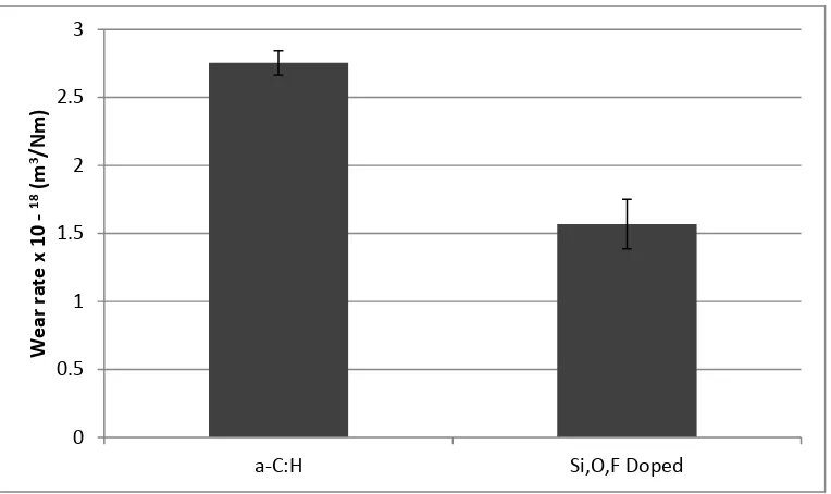
Figure 4 Dimensional wear coefficients of the coatings examined at: 25 N, 0.81 GPa , 0.2 m/s, 100 °C. Wear of Si,O coating omitted for scaling. Error bars are the standard deviation from the average values of four contact profilometry measurements. The Si,O coating is omitted for scaling.
3.4 Coating hardness
The hardness of the novel and non-doped coatings within the worn area were obtained to ascertain whether hardness was playing a key role in wear performance and whether it changed with wear. Prior to tribotesting the DLCs are all within a similar range of each other in terms of coating hardness (Table 2). The hardness within the worn area of the Si,O,F doped coating (15.29 ± 1.77 GPa) remains unchanged after wear testing. This suggests that mechanical hardness is not the key issue in this case, with respect to wear reduction. The slight increase observed in coating hardness in the worn area for the a-C:H coating (22.82 ± 1.98 GPa) could be due to a variety of causes.
3.5 Surface analysis
XPS analysis of the Si,O,F plate (Figure 5) within the worn area confirms the presence, and therefore preservation of, doping elements as well as a trace amount of sulphur.
0 0.5 1 1.5 2 2.5 3
a-C:H Si,O,F Doped
W
e
a
r
ra
te
x
1
0
-1
8(m 3/N
m
10
Figure 5 XPS data from the Si,O,F doped DLC. Carbon excluded for scaling.
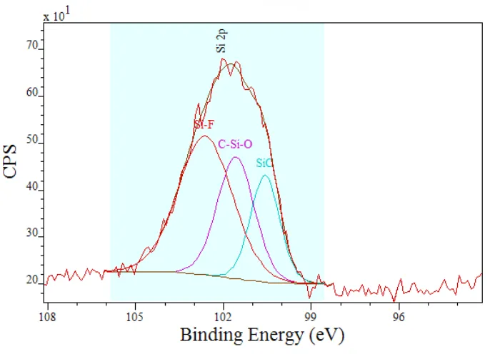
[image:11.595.126.469.407.655.2]High resolution scans were conducted for the Si peak region to verify peak components (Figure 6). There appear to be three main peak contributions to the Si 2p peak window. These peaks have been constrained to the natural FWHM values (Table 4) associated with the species expected. The peaks have been attributed as: Si-F, C-Si-O and Si-C.
Figure 6 High-resolution spectra of the Si 2p peak from the Si,O,F doped plate
Table 3 Peak component attributions from the Si 2p peak
Species % atomic
concentration
Peak position (eV) FWHM
Si-F 49.6 102.6 2.7
0 5 10 15 20 25 30 35 40
F1s O1s S2p Si2p
%
A
to
m
ic
C
o
n
[image:11.595.71.519.729.771.2]11
Si-O-C 29.8 101.6 2.0
Si-C 20.7 100.6 1.4
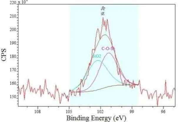
[image:12.595.72.433.160.379.2]XPS data from the counter body (Figure 7) was also obtained to ascertain the presence of a possible transfer-layer on the pin.
Figure 7 XPS analysis results of the cast iron counter body (carbon included).
The counter body contains large amounts of carbon with a peak value of 284.5 eV, suggesting this is transferred DLC from the plate. Also, F and Si are detected again suggesting the DLC has transferred from the plate. High-res scans again were recorded at Si 2p (Figure 8). The presence of SiOx and Si-O-C are noted following thorough peak component fitting with accurate FWHM values (Table 4) for expected compounds.
Figure 8 High-resolution spectra of the Si 2p peak from the pin mated against the Si,O,F doped plate 0
5 10 15 20 25 30 35 40 45 50
C1s F1s Fe2p O1s S2p Si2p
%
A
to
m
ic
.
C
o
n
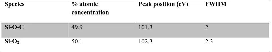
[image:12.595.142.445.499.706.2]12 Table 4 Peak attribution of the Si2p peak components
Species % atomic
concentration
Peak position (eV) FWHM
Si-O-C 49.9 101.3 2
Si-O2 50.1 102.3 2.3
3.6 ToF SIMS chemical mapping of Si,O,F DLC coating
13
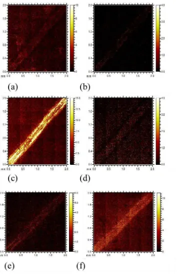
Figure 9 ToF-SIMS Chemical maps of wear track and surrounding area. (a) C2H2F- (b) SiF- (c) SiOF- (d) CF3- (e) S- (f)HS-
ToF-SIMS chemical mapping (Figure 9) shows how certain F and Si species are distributed within the DLC. Various forms of both species are present across the plate.
4. Discussion
14
within DLC films has been shown to change surface wettability, the amount of C-C bonding in DLC films and also decreases intrinsic film stress of the film (26-28). Fluorine has also been shown to reduce the hardness of DLC films (29). Inclusion of Si within DLC films is known to alter the films properties. This includes influencing the sp2/sp3 ratio, typically by increasing the sp3 fraction (7, 30-32). Furthermore, as low a doping of 1-2 % Si can reduce internal stresses associated with the film (6). Si doping is also known to affect the hardness of DLC films (1).
However, the inversion of the expected wear pattern (Table 1) for Si- and Si,O- DLCs, is notable; it would appear that doping Si,O-DLCs with F is an effective method to protect the coating from aggravated wear rates. This could be hugely beneficial as Si dopants increase coating adherence to the substrate and alter many of the parameters listed above (7, 11, 30). Being able to effectively include all of Si’s beneficial properties into the DLC coating without the intrinsic increase in wear would be an excellent prospect for DLCs within many applications. Adding to this the enhanced wear resistance of the Si,O,F DLC, when compared to the a-C:H DLC, goes on to further prove that inclusion of this tri-dopant system is indeed an effective wear protection strategy.
4.1 Coating attributes
The Si,O coating tested here is used as a reference to the Si,O,F coating. However it must be noted that the two have different elemental compositions. The Si,O coating has a greater % atomic amount of Si when compared with the Si,O,F DLC and less oxygen content. This is a result of the Si,O DLC being a commercial sample, leaving little control over the % incorporation of the dopants. Despite the difference in the doping levels, the coating should still act as a good reference in terms of wear performance as there are many literature precedents (Table 1) that detail that any incorporation of Si within DLCs always comes with the penalty of higher wear. The novel DLC detailed here being the exception due to tailoring of the coating with the inclusion of the F dopant.
The Si,O doped sample does have improved wettability when compared to the other two samples. Thus it can be expected that of the three coatings, the Si,O DLC should have greater affinities for any surface active lubricant additives; such as detergent species. This concept has been explored before, greater wettability allows for greater absorbance of useful species. Metal and non-metal (including Si) doping has been shown previously to foster a more metal-like surface at the DLC, maximising
tribochemical reactions (33).
Increases in the a-C:H nano hardness values were observed after wear testing. However, the novel Si,O,F coating’s nano hardness remained constant. As the oil used lacks any anti-wear additives; it is highly unlikely that a mechanically hard tribofilm forms. However, it is possible that a change in the coating microstructure could have occurred, resulting in the increased hardness. This observed change in the mechanical properties could be, perhaps, mediated by a localised change in the sp2/sp3 ratio within the coating. This has been noted in other DLCs but typically with thermal annealing in place of mechanical agitation (34). It is also possible and has been shown previously that the nano hardness values of DLC coatings (as measured by nano indentation) can and do vary with the indentation depth employed. This is especially true for a-C:H DLCs which see increased hardness at greater nano indentation depths (35). Therefore it could be the case that wearing into the coating has facilitated this observed increase in hardness, by virtue of being a greater nano indentation depth.
15
different rates. Thus, this confounding factor can be ruled out as a major contributor to the observed wear trend.
4.2 Friction
Friction values from the literature on lubricated Si-DLC, show similar friction profiles to the ones obtained herein. Typically, when lubricated with a fully formulated lubricant Si and Si,O doped DLCs exhibit coefficients of friction within the range of 0.06 – 0.12 (9-11). In water, Si DLC shows similar coefficients of friction, within the range of 0.06-0.09 (14). Initial friction data for the samples tested start at a similar value. However, by the end of the test duration Si,O,F-DLC actually has the higher friction of the three DLCs tested. The reduction in friction afforded by the a-C:H sample here is most likely due to the greater polishing wear (Figure 2) that the sample undergoes, thus reducing asperity-asperity contacts. It is also possible that, the friction reduction for the a-C:H sample could be due to oxidative wear creating more hydroxyl terminated surfaces, which are thought to influence friction (36). The same arguments are true for the Si,O doped DLC. The friction of the Si,O,F- doped sample however shows the opposite behaviour with friction increasing slightly toward the end of the test duration. This increased friction for the Si,O,F doped DLC could be indicative of the formation of a mechanically hard tribofilm (37). The Si,O doped DLC does not show the reduced friction that may have been expected when compared to the a-C:H, as seen in dry sliding experiments (3, 4). This however is in-line with literature precedents concerning DLCs in lubricated contacts where Si-DLCs friction reducing properties are markedly reduced (8, 9). Thus, it can be concluded that in boundary lubricated contacts the inherent ability of Si-DLCs to self-lubricate is compromised. This is most likely affected by inclusion of dispersant type species which are able to sequester SiOx type debris, as well as the general presence of a lubricant that is able to effectively dilute and remove any SiOx species formed. These SiOx species are widely regarded to be the cause of Si-DLCs low friction (2-4, 38).
4.3 Wear
Wear (Figure 3, Figure 4) of the tri-doped DLC is reduced on average by 43 % when compared to the a-C:H sample, showing a clear reduction in plate wear. The results here show that when Si is
incorporated into the DLC with O and F, creating a tri-doped system, the wear is dramatically reduced. This trend clearly identifies that incorporation of the highly electronegative element F protects the Si,O-DLC from high levels of wear. As the wear of the Si,O,F plate is decreased on comparison with the other two coatings tested and the friction increases; it appears that there is a tribolayer forming. This tribolayer appears similar to a ZDDP type anti-wear layer, increasing overall friction but lowering wear. This effect of mechanically hard films raising friction values has been noted previously in the literature (37, 39). The Si,O doped DLC had the highest wear of all samples tested , steel was revealed on either end of the wear scar.
4.4 Surface analysis 4.4.1 XPS
16
due to the large Fe2O3 peak the corresponding iron fluoride peak cannot be distinctly observed. Formation of an analogous species, AlF3, (when paired with an Al counter body) has been noted previously in F-DLCs (40). This then leaves the remaining Si on the counter body able to freely react with molecular oxygen to form SiOx.
4.4.2 SIMS
Enhanced build-up of a novel SiOF- fragment on the plate is clear. As this fragment is far richer in the worn area it is demonstrable that this is produced as part of the wear process. Also, there is a
noticeable amount of HS- in the wear scar; the source of HS- in this case is the lubricant. The formation of the SiOF- fragment ion appears to represent a protective tribolayer.
4.5 Proposed mechanism of wear repression
The Si-O bond strength is one of the strongest bonds silicon is able to make. The disassociation energy associated with it (798 kJ/mol) is far higher than either that of Si-C or Si-H (435 k/J mole and 298 kJ/mol respectively) (41). However, the Si-F bond is even more stable than these and represents the strongest covalent bond silicon is able to make. This is because silicon is an electropositive element whereas fluorine is the most electronegative element known. Because of this the two elements form very thermodynamically strong bonds (12, 42, 43).
The combination of both these dopants in a DLC is an exciting prospect as it appears to effectively secure silicon from oxidative wear without the need of oil-based anti-oxidant or anti-wear additives. Si,O,F doping improves the overall wear profile of the samples explored by reducing plate wear whilst maintaining low-levels of counter body wear. Literature precedents of higher wear for Si-DLCs can easily be rationalised when the broader picture is observed by inclusion of fluorine. The main mechanism for reduced friction in Si-DLC contacts is identified as being caused by production of SiOx species. These are often referred to as silicon rich oxide debris (2, 4, 11, 38). This debris represents oxidative destruction and removal of Si within the coating which in turn amplifies wear of the DLC as a whole. This will result in degradation of the coating’s microstructure as the
incorporation of additional oxygen with silicon will facilitate the breakage of bonds. This happens as there is a strong thermodynamic driving force for the Si-O bond to form at the cost of Si-C and Si-H bonds. Oxidative wear simultaneously yields reactive carbon centres that will also go on to react with oxygen or similar species; as such amplified wear for this type of coating is expected. Typically, Si bonds to O in a silica lattice type arrangement facilitated by oxygen’s bivalency, however fluorine is monovalent (44). This monovalency effectively caps the formation of a Si-O lattice network and retards oxidative wear, as the Si-F bond is stable with regards to oxygen. The lattice network relies on bridging, divalent oxygen atoms. Fluorine atoms cannot facilitate this bridging as they are only able to form one bond.
Figure 10 F-doped a-SiO2 glass
17
silicate chemistry. There are many examples of doped silicate glasses that exhibit different properties, an example of this is F doped a-SiO2 (47). This specific glass exhibits good chemical durability at the cost of low mechanical strength (48, 49). Structurally, the F doped glass is different to other glasses in that the fluorine inclusion depolymerises the silicate network (Figure 10) via non bridging fluorine, which helps to remove strained bonds (47). Stress within the silicate network is known to play a key role in the degradation of the Si-O-Si chain (40, 50). It appears that removal of this strain and increasing chemical durability of the F doped silicate glass is what is the cause of repression of wear of the tri doped DLC.
It is interesting to note that the Si,O,F-DLC has lower wear than the a-C:H sample which contains no Si dopant. This is further evidence for the formation of a protective glassy film composed of SiOF which is repressing wear as a whole and not just protecting the Si within the coating. Coupled with this is the potential of the SiOF glass species to increase surface wettability and thus adsorption of useful species. The noticeable appreciation of HS- in the worn area would indicate that the worn area is indeed accruing tribologically relevant species which is evidence for increased surface wettability. 5. Conclusions
A novel, tri-doped DLC has been produced that exhibits enhanced wear resistance both when compared with Si-DLC and with a-C:H DLC films.
The novel DLC appears to mitigate wear by producing a SiOF containing species in the worn area that appears to limit oxidative wear.
It can be concluded that inclusion of F with Si impedes the wear of the coating, this is especially relevant to Si-DLCs as a whole, which typically undergo higher wear when compared to non-doped DLCs.
The friction performance of the coating in low-additive oil is comparable with the other DLCs tested.
The mechanical parameters of the coating are also comparable, indicating the enhanced wear resistance is indeed due to the specifically tailored tribochemistry of the coating; as opposed to the hardness of the film.
6. Acknowledgements
The authors would like to thank Dr Naoko Sano at NEXUS, where X-ray photoelectron spectra were obtained. NEXUS is the National EPSRC XPS User's Service at Newcastle University, an EPSRC Mid-Range Facility. The authors would also like to thank Mr Adrian Eagles at Leeds University for help with contact profilometry measurements. Finally, the authors would like to thank Dr Frederic Meunier and Laureline Kilman at Oerlikon Sorevi for help and advice concerning the coatings tested herein.
7. References
1. K M V J D -doped,
metal-doped (Ti, WC), and non-metal-doped (Si) diamond-like carbon against steel under boundary lubrication, with and without oil additives. Thin Solid Films. 2006, 515(4), pp.2734-2747.
2. Kim, M.-G. et al. Tribological behavior of silicon-incorporated diamond-like carbon films.
Surface and Coatings Technology. 1999, 112(1 3), pp.204-209.
18
4. Oguri, K. Two different low friction mechanisms of diamond-like carbon with silicon coatings formed by plasma-assisted chemical vapor deposition. J. Mater. Res. [Online]. 1992, 7(6). Available from:
http://journals.cambridge.org/download.php?file=%2FJMR%2FJMR7_06%2FS088429140001 6721a.pdf&code=dd6d0bd5bf31d490f111c69b82140018
5. Gilmore, R. and Hauert, R. Comparative study of the tribological moisture sensitivity of Si-free and Si-containing diamond-like carbon films. Surface and Coatings Technology. 2000,
133 134(0), pp.437-442.
6. Ikeyama, M. et al. Effects of Si content in DLC films on their friction and wear properties.
Surface and Coatings Technology. 2005, 191(1), pp.38-42.
7. Iseki, T. et al. Structural analysis of Si-containing diamond-like carbon. Diamond and Related
Materials. 15(4-8), pp.1004-1010.
8. Ando, J. et al. Tribological properties of Si-containing diamond-like carbon film under ATF lubricated condition. Wear. 2009, 266(1-2), pp.239-247.
9. Ban, M. et al. Tribological characteristics of Si-containing diamond-like carbon films under oil-lubrication. Wear. 2002, 253(3-4), pp.331-338.
10. Yamaguchi, T. et al. Sliding velocity dependency of the friction coefficient of Si-containing diamond-like carbon film under oil lubricated condition. Tribology International. 2011,
44(11), pp.1296-1303.
11. Lanigan, J. et al. Tribochemistry of silicon and oxygen doped, hydrogenated Diamond-like Carbon in fully-formulated oil against low additive oil. Tribology International. (in press) 2014.
12. Speight, J.G. Lange's Handbook Of Chemistry [Online]. 1999.
13. Gilmore, R. and Hauert, R. Control of the tribological moisture sensitivity of diamond-like carbon films by alloying with F, Ti or Si. Thin Solid Films. 2001, 398 399(0), pp.199-204. 14. Wu, X. et al. Characteristics and tribological properties in water of Si-DLC coatings. Diamond
and Related Materials. 2008, 17(1), pp.7-12.
15. Lubwama, M. et al. Characteristics and tribological performance of DLC and Si-DLC films deposited on nitrile rubber. Surface and Coatings Technology. 2012, 206(22), pp.4585-4593. 16. Perez Delgado, Y. et al. Impact of wire-EDM on dry sliding friction and wear of WC-based and
ZrO2-based composites. Wear. 2011, 271(9 10), pp.1951-1961.
17. Kalin, M. and Polajnar, M. The Effect of Wetting and Surface Energy on the Friction and Slip in Oil-Lubricated Contacts. Tribology Letters. 2013, 52(2), pp.185-194.
18. Deval, J. et al. Reconfigurable hydrophobic/hydrophilic surfaces in microelectromechanical systems (MEMS). Journal of Micromechanics and Microengineering. 2004, 14(1), p.91. 19. Veres, M. et al. Characterisation of a-C:H and oxygen-containing Si:C:H films by Raman
spectroscopy and XPS. Diamond and Related Materials. 14(3-7), pp.1051-1056.
20. Takabayashi, S. et al. X-ray photoelectron analysis of surface functional groups on diamond-like carbon films by gas-phase chemical derivatization method. Surface and Interface Analysis. 2010, 42(2), pp.77-87.
21. Alexander, M.R. et al. A study of HMDSO/O2 plasma deposits using a highsensitivity and -energy resolution XPS instrument: curve fitting of the Si 2p core level. Applied Surface
Science. 1999, 137(1 4), pp.179-183.
22. Paik, N. Raman and XPS studies of DLC films prepared by a magnetron sputter-type negative ion source. Surface and Coatings Technology. 2005, 200(7), pp.2170-2174.
23. Morina, A. et al. ZDDP and MoDTC interactions in boundary lubrication The effect of temperature and ZDDP/MoDTC ratio. Tribology International. 2006, 39(12), pp.1545-1557. 24. Moulder, J. et al. Handbook of X Ray Photoelectron Spectroscopy (P/N 624755).
19
25. Alexander V. Naumkin, A.K.-V., Stephen W. Gaarenstroom, and Cedric J. Powell. NIST X-ray Photoelectron Spectroscopy Database [Online]. 2000. [Accessed 2013]. Available from:
http://srdata.nist.gov/xps/
26. Rubio-Roy, M. et al. Fluorinated DLC deposited by pulsed-DC plasma for antisticking surface applications. Diamond and Related Materials. 2008, 17(7 10), pp.1728-1732.
27. Butter, R.S. et al. Production and wetting properties of fluorinated diamond-like carbon coatings. Thin Solid Films. 1997, 311(1 2), pp.107-113.
28. Bendavid, A. et al. The properties of fluorine containing diamond-like carbon films prepared by plasma-enhanced chemical vapour deposition. Diamond and Related Materials. 2009,
18(1), pp.66-71.
29. Yao, Z.Q. et al. Structural, mechanical and hydrophobic properties of fluorine-doped
diamond-like carbon films synthesized by plasma immersion ion implantation and deposition (PIII-D). Applied Surface Science. 2004, 230(1-4), pp.172-178.
30. Kato, N. et al. Spectroscopic ellipsometry of silicon-containing diamond-like carbon (DLC-Si) films. In: Arwin, H. et al. eds. Physica Status Solidi C - Current Topics in Solid State Physics, Vol 5, No 5. Weinheim: Wiley-V C H Verlag Gmbh, 2008, pp.1117-1120.
31. Papakonstantinou, P. et al. The effects of Si incorporation on the electrochemical and
nanomechanical properties of DLC thin films. Diamond and Related Materials. 2002, 11(3 6), pp.1074-1080.
32. Damasceno, J.C. et al. Deposition of Si-DLC films with high hardness, low stress and high deposition rates. Surface and Coatings Technology. 2000, 133 134(0), pp.247-252. 33. Kalin, M. et al. The Effect of Doping Elements and Oil Additives on the Tribological
Performance of Boundary-Lubricated DLC/DLC Contacts. Tribology Letters. 2004, 17(4), pp.679-688.
34. Grierson, D.S. et al. Thermal stability and rehybridization of carbon bonding in tetrahedral amorphous carbon. Journal of Applied Physics. 2010, 107(3).
35. Liskiewicz, T.W. et al. Short note on improved integration of mechanical testing in predictive wear models. Surface and Coatings Technology. 2013, 237(0), pp.212-218.
36. Kano, M. et al. Ultralow friction of DLC in presence of glycerol mono-oleate (GMO). Tribology Letters. 2005, 18(2), pp.245-251.
37. Topolovec-Miklozic, K. et al. Film Forming and Friction Properties of Overbased Calcium Sulphonate Detergents. Tribology Letters. 2008, 29(1), pp.33-44.
38. Wu, X. et al. Tribochemical reaction of Si-DLC coating in water studied by stable isotopic tracer. Diamond and Related Materials. 2008, 17(2), pp.147-153.
39. Taylor, L.J. and Spikes, H.A. Friction-Enhancing Properties of ZDDP Antiwear Additive: Part I Friction and Morphology of ZDDP Reaction Films. Tribology Transactions. 2003, 46(3), pp.303-309.
40. Sen, F.G. et al. Low friction and environmentally stable diamond-like carbon (DLC) coatings incorporating silicon, oxygen and fluorine sliding against aluminum. Surface & Coatings
Technology. 2013, 215, pp.340-349.
41. Lide, D.R. CRC Handbook of Chemistry and Physics, 84th Edition. Taylor & Francis, 2003. 42. Timms, P.L. et al. Silicon-Fluorine Chemistry. I. Silicon Difluoride and the Perfluorosilanes.
Journal of the American Chemical Society. 1965, 87(13), pp.2824-2828.
43. Rock, P.A. Chemical Thermodynamics. University Science Books, 1983.
44. Hench, L.L. and West, J.K. The sol-gel process. Chemical Reviews. 1990, 90(1), pp.33-72. 45. Spikes, H. The History and Mechanisms of ZDDP. Tribology Letters. 2004, 17(3), pp.469-489. 46. Willermet, P.A. et al. Mechanism of formation of antiwear films from zinc
dialkyldithiophosphates. Tribology International. 1995, 28(3), pp.177-187.
47. Youngman, R.E. and Sen, S. The nature of fluorine in amorphous silica. Journal of
Non-Crystalline Solids. 2004, 337(2), pp.182-186.
20
49. Committee, E.D.F.A.S.D.R. Microelectronics Failure Analysis: Desk Reference. ASM International, 2004.
50. Michalske, T.A. and Freiman, S.W. A molecular interpretation of stress corrosion in silica.