White Rose Research Online URL for this paper:
http://eprints.whiterose.ac.uk/107934/
Version: Accepted Version
Article:
Guan, Y., Zhu, Z.Q., Li, G. orcid.org/0000-0002-5956-4033 et al. (4 more authors) (2017)
Influence of pole number and stator outer diameter on volume, weight, and cost of
superconducting generators with iron-cored rotor topology for wind turbines. IEEE
Transactions on Applied Superconductivity, 27 (6). 5204009. ISSN 1051-8223
https://doi.org/10.1109/TASC.2017.2716818
© 2016 IEEE. Personal use of this material is permitted. Permission from IEEE must be
obtained for all other users, including reprinting/ republishing this material for advertising or
promotional purposes, creating new collective works for resale or redistribution to servers
or lists, or reuse of any copyrighted components of this work in other works. Reproduced
in accordance with the publisher's self-archiving policy.
[email protected] https://eprints.whiterose.ac.uk/
Reuse
Items deposited in White Rose Research Online are protected by copyright, with all rights reserved unless indicated otherwise. They may be downloaded and/or printed for private study, or other acts as permitted by national copyright laws. The publisher or other rights holders may allow further reproduction and re-use of the full text version. This is indicated by the licence information on the White Rose Research Online record for the item.
Takedown
If you consider content in White Rose Research Online to be in breach of UK law, please notify us by
Abstract—This paper investigates the influence of pole number
and stator outer diameter on the performance of superconducting (SC) generators. The SC generator has an iron-cored rotor topology. Firstly, the generator structure is introduced and the optimization procedure is described. Then the influence of design parameters on performance, in terms of generator volume, weight, SC wire utilization, and active material cost, etc., is presented. Some relationships for the optimal combinations for different performance attributes are established. In addition, the influence of SC material price on the determination of optimal stator outer diameter and pole number is discussed. Finally, the influence of SC coil area per pole on performance is also investigated.
Index Terms—Iron-cored, pole number, SC generator, stator
outer diameter, wind turbine.
I. INTRODUCTION
ind energy has developed rapidly in recent years, primarily due to the dwindling supply of easy-to-access fossil fuels and concerns over global climate change [1]. The market of onshore wind turbines is mature and the capacity is much larger than that of offshore wind turbines [2]. However, offshore wind farms are more desirable, due to the high average wind speed, limited onshore installation space, lower interference with habitats, and shorter distance between wind farms and densely populated cities near the coast, etc. In fact, the offshore wind turbine market is developing much faster than that for onshore [1] [3]. In 2007, the total capacity of wind turbines in Europe was 56.6GW, with offshore wind turbines sharing 1.1GW. In 2030, it is expected that the total capacity will reach 300GW, with a share of 120GW to be installed offshore [3]. The disadvantages of offshore wind turbines
The work is financially supported by the European Union’s Seventh Framework
Programme for research, technological development and demonstration under grant agreement No. 308974, Project name: Innovative Wind Conversion Systems (10-20MW) For Offshore Applications (INNWIND).
Y. Guan, Z. Q. Zhu, G. J. Li, F. Vedreño-Santos and M. Odavic are with Department of Electronic and Electrical Engineering, University of Sheffield, S1 3JD, UK (e-mail: {y.guan, Z.Q.Zhu, g.li, f.vedrenosantos, m.odavic}@sheffield.ac.uk)
Ziad Azar and A. S. Thomas are with Siemens Wind Power, Sheffield, S3 7HQ, UK (e-mail: {ziad.azar, arwyn.thomas}@siemens.com).
include the difficulties of constructing foundations, grid connections and maintenance, etc. Consequently, a wind farm with a smaller number of large power wind turbines is preferable to that with many small ones. The INNWIND.EU project is targeting 10~20MW wind turbines [4].
Superconducting (SC) material has the capability to carry large current densities, which makes the produced magnetic field much larger than that of a copper coil or permanent magnet (PM). Thus, the SC generator can be designed with high torque and power densities. American Superconductor (AMSC) has designed a 10MW SC generator with air-cored rotor for direct-drive wind turbines with a weight of ~150 tons. The weight can be as high as 300 tons or 500 tons if PM or copper field winding excited topologies are adopted respectively [5] [6]. This makes the SC generator a competitive candidate for the offshore wind turbine market and can significantly reduce the foundation and installation costs.
The biggest challenge of the commercialization of SC generators is the high price of SC wire. For a high temperature superconducting (HTS) generator, the cost of the HTS material could be up to 90% of the total material cost [7]. The iron-cored rotor SC generator topology has gained much attention in recent years, due to better utilization of SC material, although the weight is higher than that of air-cored topologies. The performance has been compared with other topologies in [8]-[10]. Some iron-cored rotor SC generators are designed and the performances are analyzed in [11]-[14]. The influences of design parameters, such as rotor pole width, stator outer diameter, electric loading, operating temperature of the SC wire, etc., on performance are investigated in [10][15]. DTU investigated the influence of pole number on the weight, SC wire length and active material cost of air-cored rotor SC generator in [16]. Converteam found the optimum pole number to be between 16 and 20 [17] [18]. However, both DTU and Converteam only gave the results without detailing how the results were obtained.
In this paper, the combination of stator outer diameter and pole number is investigated, because they are interrelated and exhibits an optimal combination. The investigated performance indicators include the volume, weight, SC material utilization and active material cost of the SC generator with iron-cored
Influence of Pole Number and Stator Outer
Diameter on Volume, Weight and Cost of
Superconducting Generators with Iron
-
Cored
Rotor Topology for Wind Turbines
Y. Guan, Z. Q. Zhu, Fellow, IEEE,
G. J. Li, Ziad Azar, Senior Member, IEEE, A. S. Thomas, F.
Vedreño-Santos, M. Odavic
for these optimal combinations are established.
II. GENERATOR STRUCTURE AND OPTIMIZATION PROCEDURE
A. Generator Structure
The structure of the SC generator with an iron-cored rotor topology is shown in Fig. 1 (a). The stator tooth and yoke, and rotor pole are all made of iron. The materials of the armature winding and field winding are copper and second generation (2G) of HTS material respectively. The characteristics of the HTS material can be found in Fig. 11. According to the strategy of cooling HTS material, the iron-cored rotor topology can be further divided into warm (with only HTS material cooled) and cold rotor iron (with both HTS material and rotor iron cooled) topologies. The former has a shorter cool down time due to less cold mass. The cold iron has a more stable cryogenic environment, due to the large thermal capacity caused by rotor iron. However, the cooling power is higher and the cool down time is longer [7] [19]. In this paper, the warm rotor iron topology is adopted, and the space between the field winding and the rotor pole is utilized for cryostat installation for SC coil cooling.
B. Optimization Procedure
An optimization study will be conducted for each design, with a different combination of stator outer diameter and pole number. For each design, there are many dimensional parameters which can be optimized, as shown in Fig. 1 (a). In order to simplify the optimization, some conditions are imposed:
1) The cross sectional area of the SC coil per pole is fixed at 200 mm2.
2) Some of the rotor dimensional parameters, which are related to the cryostat installation, are not optimized, as listed in TABLE I. This leads to a simplification of the optimization process of the SC generator, since the design of the cooling system is reported to be very challenging [9]. The airgap length equation in TABLE I is achieved by fitting the data of some existing electrical machines in Siemens.
The influence of the area of SC coil will be discussed in section IV. For each specific stator outer diameter and pole number, the stator yoke thickness, stator slot width and height, and rotor pole width are globally optimized to achieve the 10.5MNm electromagnetic torque with the shortest stack length Lstack. The target torque of 10.5MNm is defined based on the
requirements of a 10MW direct drive wind turbine, which are also listed in TABLE I. These requirements are supplied by Siemens Wind Power according to the EU INNWIND project. Finite element analysis (FEA) software MAXWELL is utilized for torque calculation and id=0 (The d-axis is aligned with the
rotor field excitation) control is adopted and parameter scanning is performed for global optimization.
During the optimization process, the armature DC copper loss is fixed to be 495kW to satisfy the efficiency requirement of >95%. For simplification, the armature AC loss and the
Lhalf_turn, which includes the end winding length, is (1a) [20].
(1a)
(1b)
cos (1c)
where bs is stator slot width, bT is the average width of stator
tooth, and d1, Cs, y, are shown in Fig. 1 (b).
It should be mentioned that the full pitched stator winding is adopted in the investigation. The short-pitched winding could be employed, since it can eliminate some harmonics in the no load voltage. However, if all of the machine stator windings have the same pitch, the comparison of the torque capability is fair, since the winding factors are the same. Therefore, the influence of winding pitch is not analyzed in the paper.
A parametric sweep is a useful method to highlight the influence of a particular design parameter on the particular objective. This method is adopted for investigating the influence of the combination of stator outer diameter and pole number. For each machine with specific stator outer diameter and pole number, the stator yoke thickness, stator slot width and height, and rotor pole width are optimized.
(a)
(b)
Fig. 1. Cross section and dimensional parameters of SC generator. (a) Cross section and corresponding parameters. (b) Parameters of stator coil.
[image:3.612.360.558.93.160.2] [image:3.612.359.517.370.692.2]TABLE I
PARAMETERS OF 10MWSC GENERATOR
Power (MW) 10
Speed (rpm) 9.6
Torque (MNm) 10.5
Efficiency (%) 95
hp1(mm) 40
bp1(mm) 60
hc1(mm) 60
hc2(mm) 60
hc3(mm) 60
g (mm) 2+0.001×D
bsc (mm) 12.5
hsc (mm) 8
hc3(mm) 60
Packing factor of stator slot kpac 0.6
SC coil engineering current density Jsc (A/mm2) 340
SC coil operational temperature (K) 30 SC coil maximum perpendicular flux density B (T) 1.34 Stator current density Ja (A/mm2) 3.5
Number of slots per pole per phase 4 Stator coil pitch full pitched
III. INFLUENCE OF POLE NUMBER AND STATOR OUTER
DIAMETER
A. Influence on Torque per Stack Length and Torque per Generator Volume
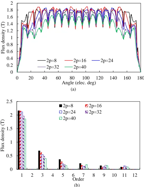
Some of the cross sections of the optimized SC generators are shown in Fig. 2. As the pole number 2p increases, the coil pitch of the stator coil reduces and the end winding length decreases, which favors fully utilizing the armature winding and increasing the torque. However, the ratio of rotor pole width to pole pitch reduces, which tends to reduce the fundamental flux density in the air gap, as shown in Fig. 3, and further reduce the torque. Consequently, there should be an optimal pole number to achieve the maximum torque. The variation of torque per stack length with pole number is shown in Fig. 4 (a). As 2p increases, the torque increases initially, then eventually the torque begins to reduce. The optimal pole number is related to the stator outer diameter. In this investigation, the optimal D/2p for torque per stack length is ~1/6m. As can be seen from Fig. 3, the maximum flux density in the airgap of the SC generator is quite high, 1.5-2T, much higher than that of the conventional PM generators, ~1T.
The variation of torque per generator active volume with pole number is shown in Fig. 4 (b). The optimal 2p for torque per volume is the same as that for torque per stack length, because the pole number does not influence the volume per stack length. For the volume in Fig. 4 (b), the length of the end windings are not considered. The torque per generator total volume (with end winding considered) can be obtained by (2).
(2)
where VG(active) and VG(total) are the active and total volumes of
the generator respectively, LG(active) and LG(total) are the active
and total length of generator respectively. The variation of generator active volume to total volume with pole number for different stator outer diameters is shown in Fig. 4 (c). When the generator is designed with a bigger diameter, a larger ratio of generator axial length will be occupied by the armature
winding. The variation of torque per generator total volume with pole number is shown in Fig. 4 (d). There exists some optimal combinations of stator outer diameter and pole number to achieve the maximum torque per generator volume.
(a) (b) (c)
(d) (e) (f)
Fig. 2. Cross sections. (a) D=7m, 2p=16. (b) D=7m, 2p=32. (c) D=7m, 2p=64. (d) D=12m, 2p=16. (e) D=12m, 2p=32. (f) D=12m, 2p=64.
(a)
[image:4.612.312.565.107.310.2](b)
Fig. 3. No load flux density in the middle of airgap, D=5m, (a) Waveforms. (b) Spectra.
0 0.2 0.4 0.6 0.8 1 1.2 1.4 1.6 1.8 2
0 20 40 60 80 100 120 140 160 180
F
lux
de
nsit
y
(T
)
Angle (elec. deg) 2p=8 2p=16 2p=24 2p=32 2p=40
0 0.5 1 1.5 2 2.5
1 2 3 4 5 6 7 8 9 10 11 12
F
lux
de
nsit
y
(T
)
[image:4.612.316.560.364.681.2](a)
(b)
(c)
[image:5.612.56.292.56.687.2](d)
Fig. 4. Variation of (a) torque per stack length, (b) torque per generator active volume, (c) ratio of generator active to total length (active length means the stator or rotor stack length, without end-winding length considered), and (d) torque per generator total volume with pole number for different stator outer diameters.
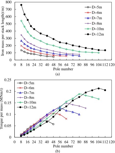
area of iron of the cross section reduces. Thus, the iron weight per stack length reduces, as shown in Fig. 5 (a). When the torque in Fig. 4 (a) is divided by the corresponding weight in Fig. 5 (a), the torque per iron mass is obtained, as shown in Fig. 5 (b). There exists an optimal pole number 2p for each stator outer diameter to achieve the maximum torque per mass. The optimal pole number increases with stator outer diameter. In addition, the optimal pole number for torque per mass should be between the optimal pole numbers for torque and mass respectively, thus, the following relationship is always established: The optimal 2p for torque per iron weight > 2p for torque per stack length. It is worth mentioning that although a combination of larger stator outer diameter and pole number favors to reduce the iron mass, as seen in Fig. 5 (b), the requirement for supporting structures for the stator and rotor becomes tougher, due to the large diameter. Consequently, the total weight of the generator may not be reduced. The influence of stator outer diameter and pole number on the supporting structure is not considered in this paper. With the supporting structure considered, the optimal stator outer diameter for torque per generator total mass will be lower than the data presented in Fig. 5 (b).
(a)
[image:5.612.322.556.346.656.2](b)
Fig. 5. Variation of iron mass and torque per iron mass with pole number for different stator outer diameters. (a) Iron mass per stack length. (b) Torque per iron mass.
C. Influences on Torque per SC Length
Because the area of SC coil per pole is fixed in the optimization, the total quantity of SC material of the generator per stack length is proportional to the pole number, as shown in
0 5 10 15 20 25 30
0 8 16 24 32 40 48 56 64 72 80 88 96 104 112 120
T or que pe r sta ck leng th (MN m/ m) Pole number D=5m D=6m D=7m D=8m D=10m D=12m 0 0.05 0.1 0.15 0.2 0.25 0.3 0.35
0 8 16 24 32 40 48 56 64 72 80 88 96 104 112 120
T or que pe r volum e ( M Nm /m ^3) Pole number D=5m D=6m D=7m D=8m D=10m D=12m 0 0.2 0.4 0.6 0.8 1 1.2
0 8 16 24 32 40 48 56 64 72 80 88 96 104 112 120
R ati o o f a cti ve to to tal leng th Pole number D=5m D=6m D=7m D=8m D=10m D=12m 0 0.05 0.1 0.15 0.2 0.25
0 8 16 24 32 40 48 56 64 72 80 88 96 104 112 120
T
or
que
pe
r volume (
MNm/ m^ 3) Pole number D=5m D=6m D=7m D=8m D=10m D=12m 0 100 200 300 400 500 600 700 800
0 8 16 24 32 40 48 56 64 72 80 88 96 104 112 120
Iron mass pe r sta ck leng th(t/m ) Pole number D=5m D=6m D=7m D=8m D=10m D=12m 0 0.05 0.1 0.15 0.2 0.25
0 8 16 24 32 40 48 56 64 72 80 88 96 104 112 120
Fig. 6 (a). The torque per SC wire length, as shown in Fig. 6 (b), can be obtained by dividing the torque in Fig. 4 (a) by the SC wire length in Fig. 6 (a). There exists an optimal pole number to achieve the maximum torque per SC wire length, and the optimal 2p for torque per SC wire length < 2p for torque per stack length.
It should be mentioned that the SC coil end length is not considered in Fig. 6. By including the end length of SC coil, the torque per SC wire total length can be obtained by
(3)
where Lsc(stack) is the length of SC wire used within the stack,
Lsc(total) is the total length of SC wire including both Lsc(stack) and
Lsc(end). Lsc(end) is the length of SC wire used in the coil end
winding. Lsc(end) can be obtained by (4).
(4)
where sc is the pitch of SC coil. The variations of
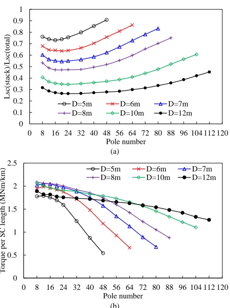
Lsc(stack)/Lsc(total) with pole number to achieve 10.5MNm are
shown in Fig. 7 (a). If the generator is designed with a larger stator outer diameter, more SC wire will be used as the end winding. The variations of torque per SC wire total length T/Lsc(total) with pole number are shown in Fig. 7 (b). For
T/Lsc(total), there are optimal combinations of stator outer
diameter and pole number, and for all stator outer diameters a lower pole number is preferable.
(a)
[image:6.612.322.557.60.374.2](b)
Fig. 6. Variation of SC wire length and torque per SC length with pole number for different stator outer diameters, the end length of SC coil is not considered. (a) SC coil length, stack length=1m. (b) Torque per SC wire length.
(a)
(b)
Fig. 7. Variation of length ratios of SC wire straight length to total length and torque per SC length with pole number for different stator outer diameters, torque=10.5MNm. (a) Lsc(stack)/Lsc(total). (b) Torque per SC total length.
D. Influence on Cost
The quotations of SC material, copper and iron are listed in TABLE II. The variations of iron, SC material, copper and total costs with pole number and stator outer diameter are shown in Fig. 8. As the pole number increases, the iron cost reduces, because less iron is utilized, as shown in Fig. 2. However, the SC material cost increases, due to poor SC material utilization, as shown in Fig. 7 (a). The copper cost is constant, which can be explained from (5), since the total copper loss and current density of the armature winding is fixed in the process of optimization.
(5)
where PCu is the copper loss, is the resistivity, J is the current
density, V is the volume of copper. Optimal combinations of stator outer diameter and pole number exist for the total cost, as found in Fig. 8 (d). The optimal pole number for total cost is larger than that for SC material cost, due to the reduction of iron cost.
TABLE II
QUOTATIONS FOR MATERIAL COST
SC material Copper Iron
100€/m 7.5€/kg 0.8€/kg
0 2 4 6 8 10 12
0 8 16 24 32 40 48 56 64 72 80 88 96 104 112 120
Leng
th of
SC
per
st
ac
k
l
eng
th
(k
m
)
Pole number D=5m
D=6m D=7m D=8m D=10m D=12m
0 1 2 3 4 5
6 7
8
0 8 16 24 32 40 48 56 64 72 80 88 96 104 112 120
T
or
que
pe
r SC
leng
th
(MN
m/
km)
Pole number
D=5m D=6m D=7m
D=8m D=10m D=12m
0 0.1 0.2 0.3 0.4 0.5 0.6 0.7 0.8 0.9 1
0 8 16 24 32 40 48 56 64 72 80 88 96 104 112 120
L
sc
(sta
ck)
/L
sc
(tota
l)
Pole number
D=5m D=6m D=7m
D=8m D=10m D=12m
0
0.5 1 1.5 2 2.5
0 8 16 24 32 40 48 56 64 72 80 88 96 104 112 120
T
orq
ue
per S
C
l
eng
th
(MNm
/km
)
Pole number
D=5m D=6m D=7m
[image:6.612.55.290.381.704.2](a)
(b)
(c)
[image:7.612.56.292.59.696.2](d)
Fig. 8. Variation of cost with pole number for different stator outer diameters, torque=10.5MNm. (a) Iron cost. (b) SC cost. (c) Copper cost. (d) Total cost.
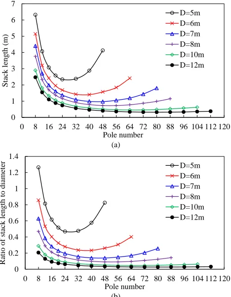
The variation of stack length with pole number for different stator outer diameters to achieve 10.5MNm of torque is shown in Fig. 9 (a). The ratios of stack length to stator outer diameter are also shown in Fig. 9 (b). As the stator outer diameter increases, the generator becomes flatter.
(a)
(b)
Fig. 9. Variations of stack length and ratio of stack length to stator outer diameter with pole number for different stator outer diameters, torque=10.5MNm. (a) Stack length. (b) Ratio of stack length to stator outer diameter.
F. Safety Margin of SC Coil
During the optimization process in section II, the current density in the SC coil is fixed to be 340A/mm2. Usually, the operating current density should include a safety margin, with respect to the critical current density, in order to safely and fully utilize the SC material. For the SC material, the critical current density and flux density are interrelated, if the temperature is fixed. Consequently, the critical current of the SC coil is difficult to determine before optimization, because an accurate value of the flux density in the SC coil cannot be obtained before the optimization. In this section, the safety margins of the SC coil for the optimizations in section III are reviewed.
The temperature of the SC coil is assumed to be 30K, and the flux density, B , perpendicular to the surface of the SC tapes is calculated. In fact, flux densities, perpendicular and parallel to the surface of SC tapes, B and B//, both have an influence on
the critical current density. Only B is considered, because B has much more significant influence on the critical current
0 0.5 1 1.5 2 2.5
0 8 16 24 32 40 48 56 64 72 80 88 96 104 112 120
Ir
on
cost (
mil
lion
Eu
ro)
Pole number
D=5m D=6m D=7m
D=8m D=10m D=12m
0 0.5 1 1.5 2 2.5
0 8 16 24 32 40 48 56 64 72 80 88 96 104 112 120
SC
c
ost (
mil
lion Eur
o)
Pole number
D=5m D=6m D=7m
D=8m D=10m D=12m
0 0.02 0.04 0.06 0.08 0.1 0.12
0 8 16 24 32 40 48 56 64 72 80 88 96 104112120
C
oppe
r c
ost (mi
ll
ion Euro)
Pole number
D=5m D=6m D=7m
D=8m D=10m D=12m
0 0.5 1 1.5 2 2.5
0 8 16 24 32 40 48 56 64 72 80 88 96 104 112 120
T
otal c
ost (mi
ll
ion
Eur
o)
Pole number
D=5m D=6m D=7m
D=8m D=10m D=12m
0 1 2 3 4 5 6 7
0 8 16 24 32 40 48 56 64 72 80 88 96 104 112 120
S
tac
k l
eng
th
(m)
Pole number
D=5m D=6m D=7m D=8m D=10m D=12m
0 0.2 0.4 0.6 0.8 1 1.2 1.4
0 8 16 24 32 40 48 56 64 72 80 88 96 104 112 120
Ra
tio of
sta
ck le
ng
th
to dia
me
te
r
Pole number
[image:7.612.322.556.152.453.2]density than B// [21]. The no load flux lines and the distribution
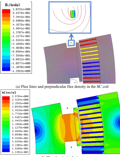
of B in the SC coil are shown in Fig. 10. The self-induced B in the SC coil for a range of stator outer diameters and pole numbers after optimization are listed in TABLE III and shown in Fig. 11. The maximum B in the SC coil does not vary significantly with stator outer diameter and pole number. With a current density of 340A/mm2, all the SC coils can operate with a safety margin of between 23%~27%. The J-B characteristic (not available online) is based on the 2G HTS material developed by Siemens Corporate Technology. Although it is desirable to keep the same safety margin across all the optimization studies, it increases the complication of optimization. It is acceptable to fix the SC coil current density, since the safety margins of the SC coil for different designs do not differ significantly. The normal flux density in the SC coil under rated load operation is close to that under no load operation, because the flux density imposed on the SC coil by the armature winding is much lower than that by the SC coil, due to the comparatively lower current density.
The safety margin of between 23% and 27% is for the straight parts of the SC coil. In some cases, the critical part may be in the end-winding, because the SC wire is under stress due to bending, which degrades the J-B characteristic of the SC material. However, for a large generator coil, the bending usually does not affect the SC material performance significantly. Therefore, the safety margin only considered for the straight parts of SC coil in this paper is safe.
(a) Flux lines and perpendicular flux density in the SC coil
[image:8.612.47.290.387.703.2](b) Flux density in the iron
Fig. 10 No load flux lines and flux density distribution, D=7m, 2p=32, (a) flux lines and perpendicular flux density in the SC coil, (b) flux density in the iron.
TABLE III
MAXIMUM PERPENDICULAR FLUX DENSITY IN THE SC COIL OF GENERATORS WITH A RANGE OF STATOR OUTER DIAMETERS AND POLE NUMBERS
D=6m D=8m D=10m D=12m 2p=16 1.320 1.356 1.372 1.377 2p=32 1.327 1.379 1.386 1.408 2p=48 1.310 1.357 1.394 1.417 2p=64 1.286 1.344 1.392 1.413
Fig. 11. Critical engineering current density - flux density characteristics of the SC material. The operational current density and maximum self-induced B in the SC coil for designs in TABLE III are also shown as operation points.
IV. OPTIMAL COMBINATIONS OF STATOR OUTER DIAMETER AND POLE NUMBER, AND INFLUENCE OF SCMATERIAL PRICE
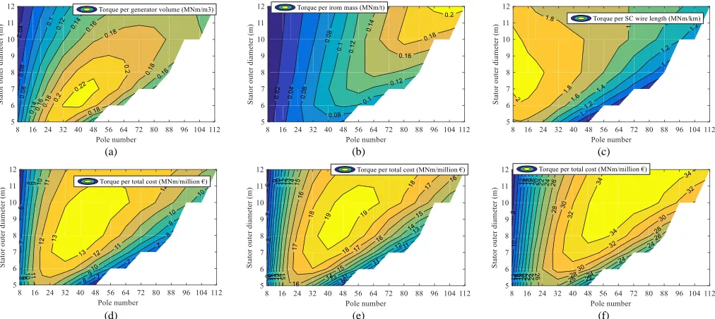
The influences of stator outer diameter and pole number on torque per generator total volume, torque per iron mass, and torque per SC wire length are summarized in this section, as shown in Fig. 12 (a)-(c). It is clear that the optimal stator outer diameter and pole number combinations for these performance indicators are different. The optimal combinations for generator volume, iron mass, and SC wire length, are located in the middle, left side and top right corner of the figures respectively. The following relationship is always established: the preferable pole number which can maximize the SC utilization < the pole number which can maximize the generator volume < the pole number which can maximize the generator mass.
The price of the 2G HTS material used in this paper is ~100€/m, which is expensive in comparison to MgB2 HTS wire. However it is expected that in the future this price will fall below 15€/m [7]. This represents a huge price reduction which could bring some changes to the distribution of optimal combinations of stator outer diameter and pole number for total cost. The torque per active material total cost with different SC material quotations are shown in Fig. 12 (d)-(f). As the price of SC material reduces, the influence of iron becomes larger comparatively. Consequently, the optimal pole number for total cost tends to be bigger, since a larger pole number leads to a reduction in iron cost. Furthermore, the final determination of D and 2p, which should be determined from a view of compromise with a range of performance indicators, could be different. Overall, a larger stator outer diameter and pole number are preferable, as the SC material price reduces.
The investigation of D and 2p involves a huge amount of computing work, because the optimization should be conducted
0 100 200 300 400 500 600 700 800 900 1000
0 1 2 3 4 5
C
ur
re
nt densit
y
(A
/m
m^
2)
Perpendicular flux density (T) Critical J-B , 30K, Siemens
J-B , 30K (with 23% safety margin) J-B , 30K (with 27% safety margin) operation point
300 350 400 450 500
1.2 1.25 1.3 1.35 1.4 1.45 1.5
for each electrical machine with specific D and 2p. Therefore, some practical components are not considered, such as the design of cooling systems and supporting structures, to make the investigation less computationally-intensive. The complexity of cooling systems for SC coils varies with pole number, since the number of SC coils varies. Furthermore, the weight, power (the power of the cooling system is related to the generator efficiency) and cost of the cooling system changes with pole number.
V. INFLUENCE OF AREA OF THE SCCOIL
For the optimization in section III, the area of SC coil per pole is fixed to be 200mm2. In this section, the influence of SC coil area on performance is investigated. For each area of SC coil, the generator is re-optimized. The optimization method is the same as that detailed in section II. It should be noted that the operating current densities of the SC coil are not fixed. In the optimization in this section, a 25% safety margin, with respect to the critical current, is maintained. For the design with D=7m 2p=32, the operating current density and maximum perpendicular flux density in the SC coil are shown in Fig. 13. The area of the SC coil appreciably affects the critical current. As the area of the SC coil decreases, the operation current density of the SC coil reduces.
Six optimized generators in section III, with D=5m 2p=8, D=5m 2p=48, D=7m 2p=32, D=7m 2p=80, D=12m 2p=8, D=12m 2p=80, are utilized respectively to investigate the influence of SC coil area on torque capability. The variations of torque per stack length with the SC coil area are shown in Fig. 14. The torque increases with the SC coil area, however, the increase tends to saturate beyond a certain point, due to the magnetic saturation in the iron. For each stator outer diameter, the curve for a design with a bigger pole number is less bended
[image:9.612.53.559.71.297.2] [image:9.612.324.550.387.517.2]than that with a lower pole number. As the pole number increases, the quantity of iron decreases, which can be seen in Fig. 2. Consequently, the influence of iron saturation reduces, and the curve becomes less bended.
Fig. 13. Critical current density - flux density characteristics of the SC material. The operating current density and maximum self-induced B in the SC coil for designs with a range of SC coil area per pole are shown as operation points. D=7m, 2p=32.
Fig. 14. Variation of torque per stack length with the SC coil area per pole of generators with a range of stator outer diameter and pole number. Base values: 5MNm (D=5m 2p=8), 7MNm (D=5m 2p=48), 15MNm (D=7m 2p=32), 9MNm (D=7m 2p=80), 5MNm (D=12m 2p=8), 30MNm (D=12m 2p=80).
0 100 200 300 400 500 600 700 800
0 1 2 3 4 5
C
ur
re
nt densit
y
(A
/m
m^
2)
Perpendicular flux density (T) Critical J-B , 30K
J-B , 30K (with 25% safety margin) operation point
Ssc=100mm2
200 400600
1000 2000
0 0.2 0.4 0.6 0.8 1 1.2 1.4 1.6 1.8 2
0 500 1000 1500 2000 2500
T
or
que
pe
r sta
ck
leng
th
(p.u.)
SC area per pole (mm^2)
D=5m, 2p=8 D=5m, 2p=48
D=7m, 2p=32 D=7m, 2p=80
D=12m, 2p=8 D=12m, 2p=80
(a) (b) (c)
(d) (e) (f)
Fig. 12. Contours of (a) torque per generator volume, (b) torque per iron mass, (c) torque per SC wire length, (d) torque per total cost, SC=100€/m, (e) torque
[image:9.612.320.552.551.688.2]VI. CONCLUSIONS
In this paper, the influences of stator outer diameter and pole number on generator volume, weight, SC material utilization and active material cost, etc., are investigated. The SC generator has an iron-cored rotor topology. There exists independent optimal combinations of stator outer diameter and pole number for defined generator volume, weight and SC material utilization specifications. For the same outer diameter, the following relationship is established for all models: the preferable pole number which can maximize the SC utilization < the pole number which can maximize the generator volume < the pole number which can maximize the generator mass. Usually, the combination of stator outer diameter and pole number should be determined by a compromise between the generator volume, weight and total cost, etc. The price of SC material has a significant influence on the final design. Overall, as the price of SC material reduces, a larger stator outer diameter and pole number are preferable.
VII. REFERENCES
[1] A.B. Abrahamsen, N. Mijatovic, E. Seiler, T. Zirngibl, C. Træholt, P.B.
Nørgård, N.F. Pedersen, N.H. Andersen, J. Østergård, “Superconducting wind turbine generators,” Supercond. Sci. Technol., vol. 23, p. 034019, 2010.
[2] M. E. Khalil, “High temperature superconducting generator design for
offshore wind turbine application,” 2015 Int. Conf. Electrical Engineering and Information Communication Technology, May 2015, pp. 1-6.
[3] A. Zervos and C. Kjaer. (Mar. 2008). Pure power: wind energy scenarios up to 2030. [Online]. Available: www.ewea.org.
[4] H. Karmaker, H. Mantak, D. Kulkarni, and E. Chen, “Design studies for a
10 MW direct drive superconducting wind generator,” 40th Annu. IEEE
Conf. Industrial Electronics Society, pp. 497-501, Oct./Nov. 2014. [5] V. Prince. (2015). Large-scale wind energy systems: 10MW and beyond.
[Online]. Available: www.magnetlab.com.
[6] G. Snitchler, B. Gamble, C. King, and P. Winn, “10MW class superconductor wind turbine generators,” IEEE Trans. Appl. Supercond., vol. 21, no. 3, pp. 1089-1092, Jun. 2011.
[7] R. H. Qu, Y. Z. Liu, and J. Wang, “Review of superconducting generator topologies for Direct-Drive Wind Turbines,” IEEE Trans. Appl. Supercond., vol. 23, no. 3, pp. 5201108, Jun. 2013.
[8] Y. Terao, M. Sekino, and H. Ohsaki, “Comparison of conventional and
superconducting generator concepts for offshore wind turbines,” IEEE Trans. Appl. Supercond., vol. 23, no. 3, pp. 520904, Jun. 2013. [9] H. Karmaker, M. Ho, E. Chen, and D. Kulkarni, “Direct drive HTS wind
generator design for commercial applications,” 2014 Int. Conf. Electrical Machines, Sept. 2014, pp. 491-495.
[10] Y. Y. Xu, N. Maki, and M. Izumi, “Performance comparison of 10-mw wind turbine generators with HTS, copper, and PM excitation,” IEEE Trans. Appl. Supercond., vol. 25, no. 6, pp. 5204006, Dec. 2015. [11] Y. Xu, N. Maki, and M. Izumi, “Study of key parameters and cryogenic
vessel structure of 10-MW salient-pole wind turbine HTS generators,” IEEE Trans. Appl. Supercond., vol. 25, no. 2, pp. 5200406, Apr. 2015. [12] J. Lloberas, “Finite-element analysis of a 15-MW high-temperature
superconductor synchronous generator for offshore wind energy
applications,” IEEE Trans. Appl. Supercond., vol. 25, no. 6, pp. 5204107, Dec. 2015.
[13] H. Yamasaki, N. Natori, and M. Furuse, “Evaluation of heat inleak in a model superconducting coil module for a wind turbine generator with iron
cores,” IEEE Trans. Appl. Supercond., to be published.
[14] X. H. Li, Y. G. Zhou, L. Han, D. Zhang, J. Y. Zhang, Q. Q. Qiu, S. T. Dai, Z. F. Zhang, D. Xia, G. M. Zhang, L. Z. Lin, L. Y. Xiao, S. W. Zhu, H. B.
Bai, B. Bian, S. P. Li, and W. N. Gao, “Design of a high temperature superconducting generator for wind power applications,” IEEE Trans. Appl. Supercond., vol. 21, no. 3, pp. 1155-1158, Jun. 2011.
[15] Y. Xu, N. Maki, and M. Izumi, “Electrical design study of 10-mw salient-pole wind turbine HTS synchronous generators,” IEEE Trans. Appl. Supercond., vol. 24, no. 6, pp. 5202706, Dec. 2014.
[16] B. B. Jensen, N. Mijatovic, and A. B. Abrahamsen. (2016). Advantages and challenges of superconducting wind turbine generators [Online]. Available: http://orbit.dtu.dk/.
[17] W. Tong, “Direct drive superconducting wind generators,” in Wind Power Generation and Wind Turbine Design, W. Tong, Southampton: WIT Press, 2010.
[18] C. Lewis, “A direct drive wind turbine HTS generator,” IEEE Power Society General Meeting, 2007, pp. 1-8.
[19] G. Klaus, M. Kilke, J. Frauenhofer, W. Nick, and H. W. Neumuller,
“Design challenges and benefits of HTS synchronous machines,” IEEE
2007 Power Engineering Society General Meeting, 2007, pp. 1-8. [20] S. K. Chen, Electrical Machine Design, Beijing: MI press, 1990. [21] S. S. Kalsi, “HTS superconductors,” in Applications of High Temperature
![TABLE I. This leads to a simplification of the optimization process of the SC generator, since the design of the cooling system is reported to be very challenging [9]](https://thumb-us.123doks.com/thumbv2/123dok_us/7753338.167998/3.612.359.517.370.692/table-simplification-optimization-process-generator-cooling-reported-challenging.webp)