Power Quality Improvement Using a
New Structure of Fault Current Limiter
Seyed Hossein Hosseini1, M. Tarafdar Hagh2, M. Jafari2, S. B. Naderi2, S. Gassemzadeh1
1Islamic Azad University, Science and research branch of East Azerbaijan
2Faculty of Electric & Electronic Engineering, University of Tabriz, Tabriz, IRAN
(Tel/Fax: +98-411-3300819; Email: [email protected])
Abstract-In this paper, power quality improvement by using a new structure of non superconducting fault current limiter (NSFCL) is discussed. This structure prevents voltage sags on Point of Common Coupling (PCC) just after fault occurrence, because of its fast operation. On the other hand, previously used structures produce harmonics on load voltage and have ac losses in normal operation. New structure has solved this problem by using dc voltage source. The proposed structure is simulated using PSCAD/EMTDC software and simulation results are presented to validate the effectiveness of this structure.
I. INTRODUCTION
Electric power quality can be defined as the capacity of an electric power system to supply energy for a load in acceptable quality. Consequently, power quality problems have became a major concern in the power systems [1, 2].
Voltage sag is a rather old power quality problem that nowadays becomes important because of sensitive loads growth [3]. Worldwide experience demonstrates that short circuit faults are the main origin of voltage sags. This problem appears especially on buses that are connected to radial feeders. Since the voltage sag during the fault is proportional to the short circuit current, an effective fault current limitation by means of a device connected at the beginning of the most exposed radial feeders will limit the expected voltage sag and improve the system power quality [4].
Superconducting FCL structures offer good ways to control the fault current levels due to their variable impedance at normal and fault conditions. Unfortunately, because of high technology and cost of superconductors, these devices are not commercially available. Therefore, replacing the superconducting coil with non superconducting coil in FCL makes it simpler and much cheaper. It should be noted that, the main drawback of NSFCL is power losses which is negligible in comparison with the total power, provided by distribution feeder [5].
In this paper, primarily main power quality problem, i.e. voltage sag, is discussed. Then in the section III proposed NSFCL circuit is introduced and its operation in the simplified power system is explained briefly. Then, the PSCAD/EMTDC software is applied to investigate the operational behavior of the NSFCL in this power system and simulation results are analyzed. Finally, it will be shown that our proposed structure is useful for power quality improvement because of voltage sag mitigating and low harmonic distortion in distribution systems.
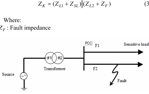
II. VOLTAGE SAG STUDY IN RADIAL POWER SYSTEM Fig. 1 shows a simplified radial power system. Feeder F1 supplies a sensitive load. With a fault in feeder F2, Point of Common Coupling (PCC) voltage reduces sharply. In case of three phase fault at the beginning of line, PCC voltage becomes almost zero and sensitive load supplying interrupts.
Positive sequence equivalent circuit of such system is shown in Fig. 2. To calculate the voltage sag, simple voltage divider method is introduced in [6].
PCC voltage can be expressed by (1):
S t S K
K
PCC V
Z Z Z
Z V
)
( +
+
= (1)
Where:
: t
Z Transformer impedance
: S
Z Source impedance
: S
V Source voltage
: K
Z Equivalent impedance of parallel feeders i.e.:
) (
)
(Z 1 Z Z 2 Z
ZK = L + SL L + (2)
In normal state, ZK in greater than (ZS+Zt). So, PCC
voltage almost is equal to source voltage. At fault condition in feeder F2, ZK changes as follow:
) (
)
( L1 SL L2 F
K Z Z Z Z
Z = + + (3)
Where:
F
[image:1.612.316.560.527.681.2]Z : Fault impedance
Figure 2. Positive sequence equivalent circuit of study system at fault condition
In three phase fault condition, ZF equals to zero and
according to (3), ZK will be small.
Consequently, referring to (1), magnitude of PCC voltage at fault interval falls strongly and sensitive load experiences a voltage interruption. To prevent this voltage sag, a proper solution, is introducing large limiting impedance between PCC and the fault. This solution is base of FCL’s operation.
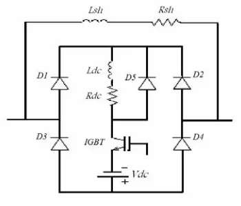
III. PROPOSED NSFCL CONFIGURATION AND ITS OPERATION Fig. 3 shows the circuit topology of proposed FCL which is composed of following part: Diode rectifier bridge, dc limiting reactor ( Ldc ) (Note that, its natural resistance ( Rdc ) is
involved too.), IGBT switch, free wheeling diode (D5), dc
voltage source and finally shunt impedance (Rsh+ j Lω sh).
In normal condition, IGBT is on. Ldc is charged to peak of
line current and therefore behaves as short circuit. Because of using semiconductor devices (diodes and IGBT) and non superconducting reactor, there are some voltage drops on bridge. Dc voltage source is utilized to compensate voltage drops on diode, IGBT and Rdc. So, its magnitude can be
achieved by (4) as follow:
2
dc dc dc DF IGBTF
V =R I + V +V (4)
It is important to note that dc voltage source can be provided by rectifiers.
Therefore, total voltage across FCL becomes almost zero and as result, FCL doesn’t affect normal operation of system.
As fault occurs, line current begins to increase, but Ldc
limits its increasing speed. When the current reaches to the maximum permissible fault current (Im), control system of
IGBT turns it off. So, the bridge retreats from feeder and shunt impedance enters to faulted line and limits fault current. At this time free wheeling diode dischargesLdc. In fact, free
wheeling diode is used to provide free route for dc reactor current.
After fault removal, IGBT turns on again and system returns to normal state.
Previously introduced structures for this application have used two numbers of thyristors at bridge branches instead of IGBT inside bridge (dc current route). Therefore, they have more complicated control system. In addition, they have no idea about voltage distortion caused by FCL. But, in this
Figure 3. Proposed NSFCL topology
structure, dc voltage source placed inside bridge resolves this problem that is explained completely at section V.
From other view point, without compensating the voltage drop across rectifier bridge, a current flows from shunt branch. Consequently, there are ac losses in the resistance of shunt impedance.
By making voltage drop on FCL almost zero, ac loss in proposed FCL is very lower than previous structures. In this case it is possible to place a large resistor (Rsh) in series with
sh
L as shown in Fig. 3. This leads to good limitation of
current and reduction of its transient at fault condition.
Next sections indicate the effectiveness of these solutions to reduce voltage sag, harmonic injection and ac power losses, consequently improve power quality.
IV. EFFECT OF PROPOSED NSFCL ON VOLTAGE SAG AND SIMULATION RESULT
As fault occurs at F2, Fig. 1, without using FCL, PCC voltage drops terribly. When FCL is installed at F2, not only reduces fault current, but also restore the non faulted feeder voltage to a normal level. In fact, during a short circuit, the voltage drop causes a corresponding drop in F1; the FCL can help to improve the power quality and the reliability of the supply network. In this section, analytical analysis of proposed NSFCL with simulation results is expressed.
Power equipment data are as follows: Source: 20 kV, 10 MVA, 50Hz, 1.608 Ω
Transformer: 20 kV/6.6 kV, 10 MVA, 0.1 pu Distribution feeder data:
Impedance of F1 = 0.314 Ω
Impedance of F2 =0.157 Ω
DC reactor of NSFCL, Ldc= 0.01 H
DC resistance of NSFCL, Rdc= 0.03 Ω
Shunt reactor of NSFCL, Lsh= 0.08 H
Shunt resistance of NSFCL, Rsh= 5 Ω
Load data in feeder F2: Resistance = 15 Ω
Inductance = 0.1 H
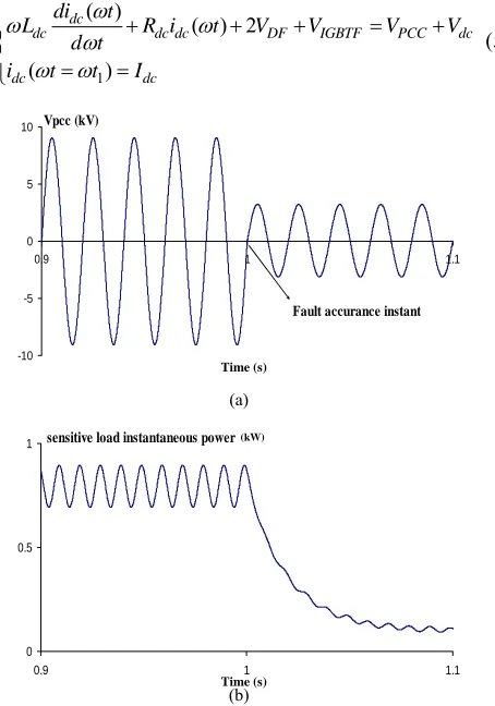
[image:2.612.64.285.54.156.2]As shown in Fig. 4, in a fault condition, PCC voltage and power transferring to sensitive load drops without FCL. With placing proposed FCL in outset of F2, as fault happens, FCL inserts large impedance into faulted line and prevents voltage sag at PCC.
Fig. 5 shows PCC voltage and sensitive load power in this state. In the first moments of fault, slight distortion appears on PCC voltage waveform caused by IGBT operation and inserting shunt impedance into line. After that PCC voltage sag will be less than 1%. The power of sensitive load in this interval hasn’t any sensible change.
In comparison with operation of structures introduced in [3], [7] and [8], using IGBT switch at dc current route instead of thyristor at bridge branches, in proposed NSFCL, leads to mitigation of sag and distortion in PCC voltage just after fault occurrence (Fig. 6).
As shown in simulation results, proposed NSFCL can resolve voltage sag problem properly.
Fig. 7 shows line current of F2, dc reactor and shunt impedance current (iL( )ωt , idc( )ωt and ish( )ωt respectively).
As shown in Fig. 7(b), between fault occurrence instant (t0)
and line current rising to its normal condition’s peak instant (t1), dc reactor current doesn’t change. From instant t1 to t2
(IGBT operation instant), dc reactor charges according to differential equation (5):
1
( )
( ) 2
( )
dc
dc dc dc DF IGBTF PCC dc
dc dc
di t
L R i t V V V V d t
i t t I
ω
ω ω
ω ω ω
⎧ + + + = +
⎪ ⎨
⎪ = =
⎩
(5)
-10 -5 0 5 10
0.9 1 1.1
Vpcc (kV)
Fault accurance instant
(a)
0 0.5 1
0.9 1 1.1
sensitive load instantaneous power
(b)
Figure 4. (a) PCC voltage and (b) sensitive load instantaneous power without NSFCL
(a)
0 0.5 1
0.98 1 1.02 1.04
Sensitive load instantaneous power (kW)
(b)
Figure 5. (a) PCC voltage and (b) sensitive load instantaneous power with proposed NSFCL
-10 -5 0 5 10
0.995 1.005 1.015 1.025
With thyristor switch With IGBT Vpcc (kV)
(a)
0 0.5 1
0.995 1.015 1.035 1.055 1.075
With thyristor switch With IGBT
(b)
Figure 6. (a) PCC voltage and (b) sensitive load instantaneous power waveforms before and after optimization
-0.4 0 0.4 0.8
0.95 0.99 1.03 1.07 1.11 1.15
Idc IL Ish (kA)
(a)
-0.7 0.995
Idc IL Ish
t0 t1 t2
(b)
Figure 7. (a) line, dc reactor and shunt impedance current and (b) with detailed
Time (s) Time (s)
Time (s)
Sensit
iv
e lo
a
d
inst
a
n
ta
neo
u
s
po
wer (
k
W)
Time (s)
Current (kA) Time (s)
Time (s) (kW)
[image:3.612.328.553.0.727.2] [image:3.612.63.290.370.694.2] [image:3.612.333.536.497.701.2]Where:
dc
I : dc reactor current at normal condition that equals to the
peak of line current.
) ( t dc
i ω : dc reactor current between t1 tot2.
DF
V : Forward voltage drop on diodes.
IGBTF
V : Forward voltage drop on IGBT.
sin( ) PCC P
V =V ωt
dc
V : dc voltage source magnitude, see (4).
With solving (5):
1
( )
( ) sin( )
dc dc R t t L dc dc
i t Ae B t K
ω ω
ω ω ϕ
− −
= + − + (6)
Where:
1
2 2 2
2 2 2
2
sin( )
2
arctan( )
DF IGBTF dc P dc dc dc dc dc P dc dc
dc DF IGBTF
dc
dc dc
dc
V V V
V
A I t
R
R L
V B
R L
V V V
K R L R ω ϕ ω ω ω ϕ + − ⎧ = − − + ⎪ + ⎪ ⎪ ⎪ = ⎪ + ⎨ ⎪ = − − ⎪ ⎪ ⎪ = ⎪ ⎩ (7)
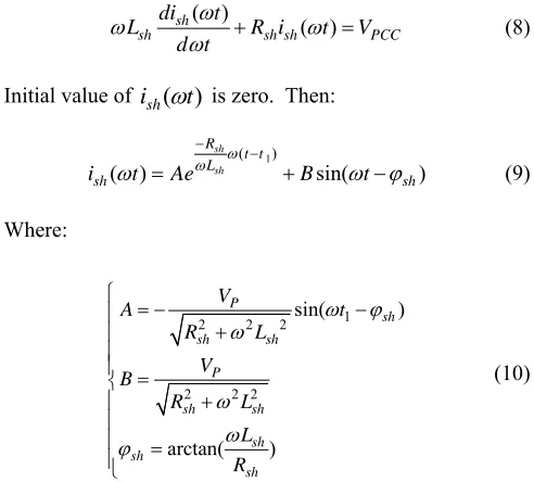
In addition, at this interval, voltage across FCL increase shunt impedance current. Differential equation of this current is expressed by (8):
( )
( )
sh
sh sh sh PCC
di t
L R i t V
d t
ω
ω ω
ω + = (8)
Initial value of ish(
ω
t) is zero. Then:1
( )
( ) sin( )
sh sh R t t L sh sh
i t Ae B t
ω ω
ω ω ϕ
− −
= + − (9)
Where:
1
2 2 2
2 2 2
sin( ) arctan( ) P sh sh sh P sh sh sh sh sh V A t R L V B R L L R ω ϕ ω ω ω ϕ ⎧ = − − ⎪ + ⎪ ⎪ ⎪ = ⎨ + ⎪ ⎪ ⎪ = ⎪⎩ (10)
IGBT control strategy is based on maximum permissible fault current (Im). Between t1 to t2, line current (iL( )ωt )
equals to idc( )ωt plus ish( )ωt (Fig.7(b)). When IGBT current
exceeds from Im, control system of IGBT turns it off. If in (6), ( )
dc
i ωt be equal to Im, IGBT operation instant (t2) will be
calculated. After t2 , diode bridge retreats and shunt
impedance limits fault current. Until fault clearance instant and turning on of IGBT, line current follows (9). In addition, at this interval, idc( )ωt is discharged by D5 as following
equation:
2
( )
( ) 0
( )
dc
dc dc dc
dc m
di t
L R i t d t
i t t I
ω ω ω ω ω ω ⎧ + = ⎪ ⎨ ⎪ = = ⎩ (11)
As a result:
2 ( ) ( ) dc dc R t t L dc m
i t I e
ω ω ω
− −
= (12)
It is important to note that (9) is composed of two parts; exponential and sinusoidal. Exponential part causes a transient in line current (as shown in Fig. 7(a)) that duration of this transient depends on shunt impedance time constant (Lsh Rsh ).
In case that shunt branch is consist of reactance only (e.g. in [7]), time constant becomes greater and as result transient of current last more time. By placing a large resistance in series with the reactance, current transient damps in short time.
V. HARMONIC STUDY
[image:4.612.46.295.79.358.2]As explained previously, using the dc voltage source in proposed structure and compensation of voltage drop on the power electronic devices and dc reactor resistance reduces THD of voltage waveform.
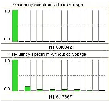
Fig. 8 shows load voltage at normal operation of power system with and without dc voltage source and Fig. 9 shows the frequency spectrum of load voltage.
By using proposed NSFCL the distortions of voltage waveform decreases to lower values, as shown in Fig. 8 and Fig. 9. Simulation results prove this statement as follows: THD of load voltage in case of NSFCL without dc voltage source: 2.789%
THD of load voltage in case of NSFCL with dc voltage source: 0.117%
It is important to note that the THD of load voltage is near to zero for proposed structure.
-10 -7 -4 -1 2 5 8
0.28 0.282 0.284 0.286 0.288 0.29 0.292 0.294 0.296 0.298 0.3 0.302 0.304 0.306 0.308 0.31
Time (s) L o a d vo lt ag e (kV )
[image:4.612.53.299.411.633.2]With dc voltage source Without dc voltage source
[image:4.612.322.561.547.665.2]Figure 9. Frequency spectrum of load voltage
VI. CONCLUSION
Today the problem of power quality improvement is very important. In this paper the new topology of a NSFCL structure is introduced. Power quality improvement and fault current limiting operation due to the control method were analyzed through the computer simulation. Proposed NSFCL is capable of mitigating voltage sags to acceptable levels and has high speed because of using IGBT switch instead of thyristors. Note that the control system of this structure is more
simpler than previous ones, because it uses IGBT at dc current path instead of two numbers of thyristor at the bridge branches. In addition, dc voltage source placed in FCL structure reduces its THD and ac losses in normal operation. In general this type of NSFCL is useful for power quality improvement because of voltage sag mitigating and low harmonic distortion in distribution systems.
REFERENCES
[1] Timothy J. Browne, Gerald T. Heydt. “Power Quality as an Educational Opportunity,” IEEE Trans. Power Del., vol. 23, no. 2, pp. 814-815, May 2008.
[2] Nesimi Ertugrul, Ameen M. Gargoom, Wen. L. Soong. “Automatic Classification and Characterization of Power Quality Events,” IEEE
Trans. Power Del., vol. 23, no. 4, pp. 2417-2425, October 2008.
[3] M. Abapour, Seyed Hossein Hosseini, M. Tarafdar Hagh. “Power Quality Improvement by Use of a New Topology of Fault Current Limiter,”
ECTI-CON. , pp.305-308,2007.
[4] Stefano Quaia, Fabio Tosato. “Reducing Voltage Sags Through Fault Current Limitation,” IEEE Trans. Power Del., vol. 16, no. 1, pp.12-17,
January 2001.
[5] Mehdi Abapour, Mehrdad Tarafdar Hagh. “Nonsuperconducting Fault Current Limiter With Controlling the Magnitudes of Fault Currents,”
IEEE Trans. Power Electronics., vol. 24, no. 3, pp. 613-619, March 2009.
[6] L.E. Conrad. “Proposed Chapter 9 for predicting voltage sags (Dips) in revision to IEEE Std. 493, the gold book,” IEEE Transactions on
Industry Applications, pp. 805–821, May/June 1994.
[7] D. Jiang, Z. Lu, Z. Wu. “Anewtopology of fault-current limiter and its parameters optimization,” Proc. IEEE Power Electron. Specialists Conf., pp. 462–465, June 2003.