Integrated Probabilistic Modelling of Pitting and
Corrosion-Fatigue Damage of Subsea Pipelines
Ehsan Arzaghi
a*, Rouzbeh Abbassi
a, Vikram Garaniya
a, Jonathan Binns
a, Nima Khakzad
b, Genserik Reniers
bNational Centre for Maritime Engineering and Hydrodynamics, Australian Maritime College, University of Tasmania,
Launceston, Tasmania, Australia
Safety and Security Science Group, TU Delft, Delft, The Netherlands * Corresponding Author, Email: earzaghi@utas.edu.au
Abstract -
Degradation of subsea pipelines in the presence of corrosive agents and cyclic loads may lead to the failure of these structures. In order to improve their reliability, the deterioration process through pitting and corrosion-fatigue phenomena should be considered simultaneously for prognosis. This process that starts with pitting nucleation, transits to fatigue damage and leads to fracture, is influenced by many factors such as material and process conditions, each incorporating a high level of uncertainty. This study proposes a novel probabilistic methodology for integrated modelling of pitting and corrosion-fatigue degradation processes of subsea pipelines. The entire process is modelled using a Dynamic Bayesian Network (DBN) methodology, representing its temporal nature and varying growth rates. The model also takes into account the factors influencing each stage of the processes. To demonstrate its application, the methodology is applied to estimate the remaining useful life of high strength steel pipelines. This information along with Bayesian updating based on monitoring results can be adopted for the development of effective maintenance strategies.Keywords:Corrosion-Fatigue, Probabilistic Modelling, Dynamic Bayesian Network, Subsea Pipelines
1.
INTRODUCTION
One of the major causes of failure in offshore structures such as oil and gas pipelines is degradation of structural properties during their lifespan (Dey & Gupta, 2001; Sulaiman & Tan, 2014). Corrosion is the most well-known form of steel deterioration resulting in generation of pits or more extended damage. Fatigue, on the other hand, is the disintegration of material due to cyclic loads applied on the structure. Coupled corrosion-fatigue results from applied cyclic stresses in tandem with presence of corrosive agents, where localized corrosion in the form of pits may provide the required conditions for initiation of fatigue crack initiation.
Many parameters including material properties and environmental conditions influence this process. These factors, each incorporating a level of uncertainty, may be adopted to estimate the remaining useful life of the structure. While these predictions will provide reliable measures for improving maintenance strategies, a dynamic framework is also required for updating the estimations based on new observations during the service life.
A great deal of research has been conducted to predict the state of damage and fatigue life in steel and aluminum alloy structures subjected to pitting and corrosion-fatigue. Kondo (1989) developed a model for the prediction of fatigue crack initiation time based on pit growth, however, the damage process was not entirely simulated. Goswami and Hoeppner (1995) proposed a seven-stage model that considers the effect of electrochemical processes on pit formation as well as the role of pitting in fatigue crack initiation; however, this model was conceptual and failed to provide a computational framework. A probabilistic model is developed by Harlow and Wei (1994) for prediction of corrosion-fatigue life comprising the time for crack initiation, surface crack growth and the growth of damage to the critical size. This model, however, does not consider the time of pit nucleation as well as the effect of short cracks in service life modelling. Kaynak and Baker (1996) assessed the effect of short cracks on fatigue life of steel structures concluding that the growth rates of short cracks are different (usually smaller) from those of long cracks. Shi and Mahadevan (2001) proposed a mechanics-based probabilistic model of the entire pitting and corrosion-fatigue process suggested by Goswami & Hoeppner (1995). They adopted Monte Carlo simulations and the First-Order Reliability Method (FORM) approach to conduct the probabilistic analysis. Although, their framework provides a guideline for estimating fatigue life, application of FORM may result in computational complications.
computational time of inference, by factorizing the joint probability distribution of the parameters of interest based on local dependencies.
Various applications of BN in risk and reliability engineering can be found in Weber et al. (2012), (Abbassi et al., 2016), Bhandari et al. (2016) and Yeo et al. (2016). However, only a few studies adopted BNs for modelling deterioration processes in structures. Friis-Hansen (2000) studied the application of Dynamic Bayesian Network (DBN) in modelling fatigue crack growth of offshore jacket structures. The developed probabilistic network was also used to identify optimum inspection plans. Straub (2009) developed a generic computational framework using DBN for modelling deterioration processes with potential applications in inspection, maintenance, and repair planning.
In the present study, a probabilistic methodology is developed for modelling corrosion-fatigue deterioration in offshore structures. This methodology consolidates the entire damage process including pit nucleation, pit growth transited to short and long fatigue cracks, and the fracture of structure. To improve the accuracy of corrosion-fatigue life estimations, the model incorporates the randomness in the parameters influencing the process. For this purpose, DBN is adopted as an efficient probabilistic tool. The advantages of this methodology are illustrated through the remaining useful life assessment of an offshore pipeline subjected to pitting and corrosion-fatigue.
2.
BAYESIAN NETWORKS
2.1 Conventional Bayesian network
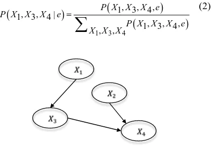
BNs are directed acyclic graphs used for reasoning under uncertainty by considering the causal relationships (represented by directed edges) among a number of random variables (represented by chance nodes) (Pearl, 1988). BN estimates the joint probability distribution of a set of random variables based on the conditional independencies and the chain rule, as in Eq. 1:
(
, ,)
(
( )
)
1
) 1 2 , |
(
n
P X X Xn P X pa X
P U i i
i
… =
=
=
∏
(1)
where P U
( )
is the joint probability distribution, andpa X( )
i is the parent set of random variable Xi. Figure 1 depicts a conventional BN comprising random variables X1-X4. As the main advantage of Bayesian networks, when new information about any of the chance nodes becomes available, the model can update the probabilities for a more efficient knowledge elicitation. For instance, if variable X2 is observed to be in state e, the joint probability distribution is updated based on Bayes’ theorem:(
)
(
)
(
)
1 3 4
, , ,
1 3 4
, ,
1 3 4
, , ,
1 3 4
, |
,
P X X X e
P X X X e
P X X X e X X X
=
∑
(2)
Figure 1. A conventional Bayesian network
2.2 Dynamic Bayesian network
Dynamic Bayesian networks (DBNs) particularly represent stochastic processes and enable modelling of temporal behaviour of a set of random variables (Jensen & Nielsen, 2007). Figure 2 illustrates a DBN in which the time line is divided into a discrete number of time slices
[ ]
0,
[image:2.612.341.553.72.216.2]t∈ T . That is, a node in time slice 1i+ may be conditionally dependent on a node in time slice i as well as its parents in time slice 1i+ .
Figure 2. A Dynamic Bayesian network
The transition between two consecutive time slices may be for instance dependent upon the physical features of the stochastic process being modelled. A detailed explanation of inference algorithms developed specifically for DBN structures can be found in Murphy (2002).
3.
PITTING AND CORROSION-FATIGUE
MODELLING METHODOLOGY
[image:2.612.318.551.392.452.2]with pit nucleation time (tpn) and eventually resulting in fracture. This process also includes three damage growth times for pit (tpg), short crack (tsc) and long crack (tlc) as well as two transition stages, i.e., “pit-to-crack transition” and “short-crack to long–crack transition”.
Figure 3. Different stages of pitting corrosion-fatigue life
fl pn pg sc lc
t =t +t +t +t (3)
The method for computation of each component of the total failure time represented in Eq. (3) will be discussed in the following subsections:
3.1 Pit Nucleation
The time for pit initiation has attracted a great deal of research, yet the dependence on many influencing factors such as materials and electrochemical has not been fully investigated. Hence, the developed model considers this stage of damage life as a random variable modelled by a lognormal distribution. The adopted distribution parameters, suggested by Shi and Mahadevan (2001) are later provided.
3.2 Pit Growth
According to Kondo (1989) and Harlow and Wei (1994), pits are assumed to remain in a hemispherical shape while growing at a constant volumetric rate. This yields a pit growth rate, given by:
2 0 2
exp p
P p
C dc
dt c
MI H
C
nF RT
π
ρ
=
∆
= −
(4)
(5)
where cis the pit radius, M is the molecular weight of the material, IP0is the pitting current constant, nis the valence number, F=96, 514(c/mol) is Faraday’s constant, ρ is density, ∆H is the activation energy,
8.314
R= (J/molK) is the universal gas constant, and T
is the temperature.
The transition from pit growth to crack initiation is dependent on mechanical characteristics such as stress intensity factor,∆K. Two criteria is considered as the
boundary conditions for crack initiation: (1) the stress intensity factor for the equivalent surface crack growth of the pit reaches the threshold stress intensity factor of the fatigue crack growth (Eq. (6)), and (2) the fatigue crack growth rate exceeds the pit growth rate.
pit crack
K K
∆ = ∆ (6)
Kondo (1989) suggests that the critical crack length (ccr) that satisfies the conditions for transition from pit growth and crack initiation can be calculated as:
2
1 2
2 2.24
cr cr
K Q c
πα σ
∆
= ∆ (7)
where Q= =1 1.464α1.65 is the shape factor,
0.7 a
c
α = = is the aspect ratio of pit (cand a are half
length of the major and minor axes of pit shape), 2.4
cr
K Mpa m
∆ = is the threshold stress intensity factor, and ∆σ is the stress range experienced by the structure.
3.3 Short and Long Crack Growth
Long cracks are usually considered when using fracture mechanics for fatigue analysis, and Paris law is widely used for estimating damage sizes. The effect of short cracks on fatigue life has attracted researchers’ attention, however, there is no explicit formula derived for short crack growth. According to Kaynak and Baker (1996) and (Shi & Mahadevan, 2001), a probabilistic model based on Paris law that accounts for the uncertainty of parameters such as stress intensity factor may be applied. Eq.
(8)
represents the empirical formula for damage growth:( )m da
C K
dN = ∆
(8)
where 𝑁𝑁 is the number of applied load cycles, 𝐶𝐶 and 𝑚𝑚 are material parameters specifically obtained for short and long cracks resulting in two identical growth rates from the equation. Δ𝐾𝐾 is the stress intensity factor, which can empirically be expressed as:
( )
K Y c σ πc
∆ = ∆ (9)
that the geometry function is independent of crack depth c and the stress range ∆σ follows a Weibull distribution, an analytical solution can be achieved (Madsen et al., 1986):
2
2 2 2
1
1 1
2
, 2
m m
m U
m m t
m t
a a M SA m
m m
S C N Y
B π
− −
+
= Γ + −
= + ≠
(10)
(11)
where Aand B are the scale and shape parameters of the Weibull distribution, respectively, and Γ is the gamma function. Eq. (10) enables the computation of crack size in current time step as a function of crack size in the previous time step and the material constants m and C, where these parameters are obtained from empirical models for short and long cracks. Different methods are developed to identify the transition size cthfrom short crack growth to long crack growth. Kaynak and Baker (1996) suggested this value is about 1 to 2 mm for En7A steel. Similarly, in this study the critical size is regarded as a random variable with a mean value of 2 mm.
3.4 Probabilistic Analysis and BN Model
The probability analysis was performed using Monte Carlo simulations in tandem with implementation of a DBN. To estimate the time for the initial part of damage life where pitting corrosion is dominant, 104 samples where generated from random variables involved in Eq. (4), (5) and (7). The distributions of these variables are listed in Table (1). It should be noted that initial pit size (C0) was considered as the initial condition when solving
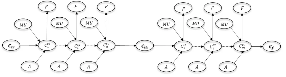
Eq. (4). The remainder of service life, where fatigue damage progresses, is estimated using a DBN. For this purpose, the generic DBN developed by Straub (2009) was adopted to model each of the two growth processes indicated in Figure 4. The developed network qualitatively represents a deterioration process describing the state of damage over the life time divided into a discrete number of slices. That is, the damage size is a function of the initial condition (nodeCcr) that is followed by the process of short crack growth (nodes C1sc to Cnsc), transition to long crack at a critical crack size (node Cth) and eventually the long crack growth process (nodes
1 lc
C to Cmlc). The occurrence of failure event is assessed by defining a limit state G, as :
G=Cf −Ci (12)
where Ciand Cf are the actual and critical crack size, respectively.
4.
APPLICATION: CORROSION
FATIGUE DAMAGE OF A SUBSEA
PIPELINE
[image:4.612.67.550.525.656.2]To demonstrate the applicability of the developed method in predicating corrosion-fatigue service life, a numerical study is carried out on the failure of an offshore pipeline. The mechanical properties of the structure are listed in Table 2. It is assumed that N=106C load cycles are experienced by the pipeline every year and critical size of damage for failure is Cf =10 10× −3m
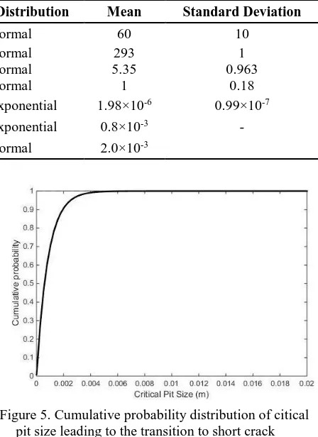
Table 1. Random values used in pitting corrosion-fatigue model
Variable Description Distribution Mean Standard Deviation
σ
∆ Stress range (MPa) Normal 60 10
T Temperature (K) Normal 293 1
A Weibull scale parameter (MPa) Normal 5.35 0.963
MU Model uncertainty Normal 1 0.18
0
C Initial pit size (m) Exponential 1.98×10⁻⁶ 0.99×10⁻⁷
cr
C Initial crack size (m) [from Monte Carlo sim] Exponential 0.8×10⁻³ - th
[image:5.612.332.556.96.404.2]C Fatigue crack threshold (short to long) (m) Normal 2.0×10⁻³
Table 2. Deterministic values used in pitting corrosion-fatigue model
Variabl
e Description Mean
ρ Density (gm/m3) 7.8×10⁶
n Valence 2
M Molecular weight (gm) 55.75
H
∆ Activation energy (KJ/mol) 5.0×10⁴
, sc lc
m m Short/long crack growth
exponent 3.0
sc
C / Clc Material parameter for short/long crack
2.17×10⁻¹³ 1.45×10⁻¹⁴
Y Geometry function 1
B Weibull shape parameter 0.66
N Load cycles 106 / year
The results of Monte Carlo simulation showed that the critical pit size for transition to short crack has a mean of
[ ] 8 10 4
E Ccr = × −
m. The cumulative probability distribution of this variable is presented in Figure 5. This distribution was discretized into 20 exponentially growing intervals which form the upper bounds of states of damage size nodes in the DBN. This was performed to avoid rounding errors caused by uniform interval lengths in the last intervals where the probabilities are significantly low.
As illustrated in Figure 4, the DBN model contained two consecutive periods corresponding to corrosion fatigue cracks with different growth rates. An adequate number of time slices were included in the short crack growth process so that the mean size of predicted damage equals the critical transition size,Cth, before long crack growth is initiated. Then the long crack process was extended for a number of time slices (each representing a year) until fracture occurs,P F
(
= =1)
1.Figure 5. Cumulative probability distribution of citical pit size leading to the transition to short crack
Figure 6. Cumulative probability distribution of corrosion-fatigue life for an offshore pipeline
[image:5.612.54.301.254.433.2] [image:5.612.333.551.420.585.2]These results highlight the potential application of the developed methodology in prediction of failure events, where the estimations of corrosion fatigue service life can be adopted for optimization of inspection and maintenance plans. Moreover, by enhancing the DBN model with a monitoring capacity, the predictions can be updated along the operation period with observation of damage size or influencing parameters.
5.
CONCLUSION
This paper presents a probabilistic methodology for prediction of pitting and corrosion fatigue service life in offshore pipelines. For this purpose, Monte Carlo simulations are used to analyze the time of pit growth as well as estimating the size of pit in which transition to short crack growth occurs. It was observed that pits with mean size of about 0.8 mm have the required condition for crack initiation in steel pipelines. A DBN model was implemented for simulating short and long crack growth which may lead to fracture. The predictions suggest that in the 20th year of operation, probability of failure event is about 0.1 where this value reaches to about 0.95 in 15 years, given that no maintenance is performed on the pipeline. The results of this study highlights the capability of the method in prediction of corrosion fatigue life considering the randomness of the parameters involved in the problem. These capabilities can also be enhanced for efficient monitoring, inspection and maintenance planning strategies.
Acknowledgements
The authors affiliated with University of Tasmania gratefully acknowledge the financial support provided by National Centre for Maritime Engineering and Hydrodynamic (NCMEH) at the Australian Maritime College (AMC) of the University of Tasmania. The authors also acknowledge the support of the ARC Research Training Centre for Naval Design and Manufacturing (RTCNDM) in this investigation. The RTCNDM is a University-Industry partnership established under the Australian Research Council Industry Transformation grant scheme (ARC IC140100003)
References
Abbassi, R., Bhandari, J., Khan, F., Garaniya, V., & Chai, S. (2016). Developing a quantitative risk-based methodology for maintenance scheduling using Bayesian network. Chemical Engineering Transactions, 48, 235-240.
Bhandari, J., Arzaghi, E., Abbassi, R., Garaniya, V., & Khan, F. (2016). Dynamic risk‐based maintenance for offshore processing facility. Process Safety Progress.
Dey, P. K., & Gupta, S. S. (2001). Risk-based Model Aids Selection of Pipeline Inspection, Maintenance Strategies. Oil and Gas Journal, 99, 54-60. Friis-Hansen, A. (2000). Bayesian networks as a decision
support tool in marine applications. (PhD), Technical University of Denmark.
Goswami, T., & Hoeppner, D. (1995). Pitting corrosion fatigue of structural materials. In C. Chang & C. Sun (Eds.), Structural integrity in aging aircrafts (pp. 39-129). New York: AMSE.
Harlow, D. G., & Wei, R. P. (1994). Probability approach for prediction of corrosion and corrosion fatigue life. AIAA journal, 32(10), 2073-2079.
Jensen, F. V., & Nielsen, T. D. (2007). Bayesian Networks and Decision Graphs. New York: Springer.
Kaynak, C., & Baker, T. (1996). Effects of short cracks on fatigue life calculations. International Journal of fatigue, 18(1), 25-31.
Kondo, Y. (1989). Prediction of fatigue crack initiation life based on pit growth. Corrosion, 45(1), 7-11. Murphy, K. P. (2002). Dynamic bayesian networks:
representation, inference and learning. University of California, Berkeley.
Pearl, J. (1988). Probabilistic reasoning in intelligent systems. San Francisco, CA: Morgan Kaufmann. Shi, P., & Mahadevan, S. (2001). Damage tolerance
approach for probabilistic pitting corrosion fatigue life prediction. Engineering fracture mechanics, 68(13), 1493-1507.
Straub, D. (2009). Stochastic modeling of deterioration processes through dynamic Bayesian networks. Journal of Engineering Mechanics, 135(10), 1089-1099.
Sulaiman, N. S., & Tan, H. (2014). Third Party Damages of Offshore Pipeline. Journal of Energy Challenges and Mechanics, 1(1).
Weber, P., Medina-Oliva, G., Simon, C., & Iung, B. (2012). Overview on Bayesian networks applications for dependability, risk analysis and maintenance areas. Engineering Applications of Artificial Intelligence, 25(4), 671-682. doi:10.1016/j.engappai.2010.06.002