FAKULTI KEJURUTERAAN ELEKTRIK (FKE)
PSM TITLE:
DESIGN OF ROBOTIC STRUCTURE FOR PEOPLE WITH DISABILITIES FOR EATING AND DRINKING MOTION (EATING)
PREPARED BY:
MOHD QUSYAIRI BIN BADRUL HISHAM (4 BEKM) B011010299
SUPERVISOR:
“ I hereby declare that I have read through this report entitle “Design of Robotic Structure for People with Disabilities for Eating and Drinking Motion (Eating)” and found that it has comply the partial fulfillment for awarding the degree of Bachelor of Electrical Engineering (Mechatronic)”
Signature :
Supervisor’s Name : DR FARIZ BIN ALI @ IBRAHIM
DESIGN OF ROBOTIC STRUCTURE FOR PEOPLE WITH DISABILITIES FOR EATING AND DRINKING MOTION (EATING)
MOHD QUSYAIRI BIN BADRUL HISHAM
A report submitted in partial fulfillment of the requirements for the degree of Bachelor of Mechatronic Engineering
Faculty of Electrical Engineering
UNIVERSITI TEKNIKAL MALAYSIA MELAKA
“ I declare that this report entitle “Design of Robotic Structure for People with Disabilities for Eating and Drinking Motion (Eating)” is the result of my own research except as cited in the references. The report has not been accepted for any degree and is not concurrently submitted in candidature of any other degree”
Signature :
Student’s Name : MOHD QUSYAIRI BIN BADRUL HISHAM
ABSTRACT
ABSTRAK
Tangan robotik adalah tangan mekanikal yang mana telah diprogram untuk berfungsi seperti tangan manusia. Tujuan projek ini adalah untuk mereka tangan robotik kepada orang-orang kurang upaya bagi tujuan makan. Robot ini dapat membantu orang-orang-orang-orang kurang upaya untuk makan dan pada masa yang sama dapat mengurangkan beban atau kerja-kerja jururawat. Objektif projek ini adalah untuk mereka dan membina struktur robotik untuk orang kurang upaya untuk makan dan juga untuk menganalisis prestasi robot dari segi kebolehulangan dan ketepatan. Terdapat 4 jurnal yang telah dirujuk semasa melakukan projek ini. Berdasarkan jurnal-jurnal tersebut, reka bentuk robot telah dilakukan sebahagian demi sebahagian dan tahap kebebasan robot diputuskan. Robot ini telah dibina selepas komponen-komponen dan sistem kawalan diputuskan. Eksperimen untuk menganalisiskan prestasi robot telah dijalankan selepas robot siap dibina. Dalam mereka bentuk robot, perisian CAD (SolidWorks) telah digunakan. Semasa mereka bahagian-bahagian robot dan pemasangan bahagian-bahagian ini, perisian SolidWorks telah digunakan. Untuk bahagian elektrik pula, perisian Proteus telah digunakan. Robot ini mempunyai 4 tahap kebebasan terdiri daripada bahagian tapak, bahu, siku dan pergelangan tangan. Mikropengawal untuk robot ini adalah Atmega328 dan Arduino Duemilanove digunakan untuk mengawal motor servo dengan mengkodkan PWM kedalam Arduino . Eksperimen untuk analisis prestasi robot dalam jangka kebolehulangan dan ketepatan telah dijalankan pada semester ini dalam PSM II. Keputusan eksperimen ini adalah untuk menunjukkan kebolehan robot ini untuk mengedalikan pergerakan berterusan berkali-kali, dan untuk menunjukan berapa banyak ketepatan robot apabila mengangkat beban tanpa
TABLE OF CONTENTS
CHAPTER TITLE PAGE
ABSTRACT i
TABLE OF CONTENSTS iii
LIST OF TABLES vi
LIST OF FIGURES vii
1 INTRODUCTION 1
1.1 Motivation 1
1.2 Problem Statement 2
1.3 Objective 4
1.4 Scope of Motivation 4
2 LITERATURE REVIEW 5
2.1 Material Used 5
2.2 Actuator 6
2.3 Controller 6
2.4 Degree of Freedom 7
2.6 Propose Method 8 2.7 Conclusion of Literature Review 10
3 METHODOLOGY 11
3.1 Flow Chart of Methodology 11
3.2 Designing a Robotic Arm Parts 13
3.3 Force Calculation of the Joint 21
3.4 Component Selection 24
3.5 System Control 30
3.6 Construct the Robotic Arm 31
3.7 Experiment of the Robotic Arm 33
4 RESULT, ANALYSIS AND DISCUSSION 35
4.1 Result 35
4.2 Design Result 36
4.3 Experiment Result 38
5 CONCLUSION AND RECOMMENDATION 47
5.1 Conclusion 47
5.2 Recommendation 48
APPENDIX A: DESIGN RESULT 50
APPENDIX B: CODING OF ARDUINO 51
APPENDIX C: WEIGHT OF EACH ROBOTIC PARTS 56 APPENDIX D: ACCURACY EXPERIMENT 61 APPENDIX E: REPEATBILITY EXPERIMENT 69
APPENDIX F: USER MANUAL 75
APPENDIX G: GANTT CHART PSM II 77
LIST OF TABLES
TABLE TITLE PAGE
1.1 Number of Nurse and Ratio of Population to Phamacists 2 1999-2006
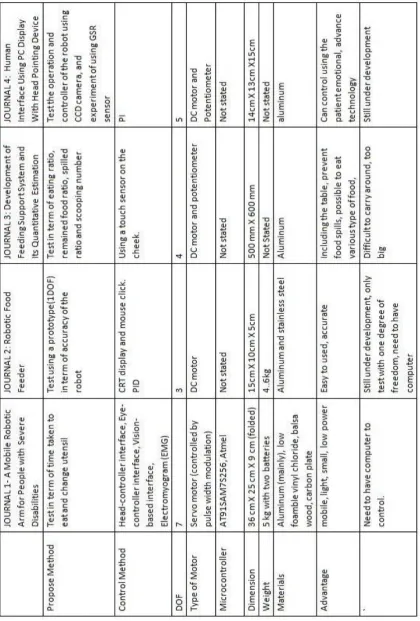
2.1 Comparison of Journals 9
3.1 Arduino Duemilanove Specification 24
3.2 C40R Servo Motor Specification 27
3.3 Futaba Servo Motor Specification 28
3.4 SG90 Micro Servo Motor Specification 29
3.5 Push Button Specification 30
4.1 Weight of Robotic Part 38
4.2 Reading at the Base 39
4.3 Reading at the Shoulder 39
4.4 Reading at the Elbow 40
4.5 Reading at the Waist 40
4.6 Base reading for Repeatability 42
4.7 Shoulder reading for Repeatability 43
4.8 Elbow reading for Repeatability 43
4.9 Waist reading for Repeatability 43
LIST OF FIGURES
FIGURE TITLE PAGE
2.1 Example of Controller 6
2.2 One DOF robot 7
3.1 Flow Chart of Methodology 12
3.2 Front View of the Robot 13
3.3 Side View of the Robot 14
3.4 Design Concept of the Robot 15
3.5 Servo Holder 16
3.6 U-Joint 16
3.7 Bases of the Robotic Arm 17
3.8 Lower Base 18
3.9 Rod 18
3.10 Upper Base 19
3.11 Rotate Bearing 19
3.12 Shoulder Motor Base 20
3.13 Arm 20
3.15 FBD of 2 DOF Robot 22
3.16 3 DOF Robot 23
3.17 Arduino Duemilanove 25
3.18 Servo Motor Components 26
3.19 Servo Control System 26
3.20 C40R Servo Motor 27
3.21 Futaba Servo Motor 28
3.22 SG90 Micro Servo Motor 29
3.23 Push Button 30
3.24 Circuit of Robot Design Using Proteus 32
4.1 Robotic Arm Design (Side View) 36
4.2 Robotic Arm (Front View) 37
4.3 Robotic Arm (Back View) 37
4.4 Graph of Angle vs. Error 41
4.5 The Comparison of Coarser Teeth 42
CHAPTER 1
INTRODUCTION
1.1 Motivation
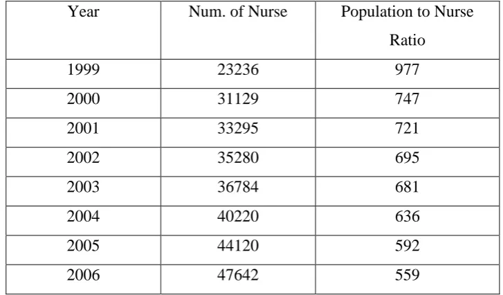
Table 1.1: Number of Nurse and Ratio of Population to Phamacists 1999-2006 Year Num. of Nurse Population to Nurse
Ratio
1999 23236 977
2000 31129 747
2001 33295 721
2002 35280 695
2003 36784 681
2004 40220 636
2005 44120 592
2006 47642 559
The nurse cannot entertain the patient because there are too many of them (patients). Using the robot, some of the patient doesn’t have to trouble the nurse when they want to eat, so the nurse can focus on the other patient that required more attention.
1.2 Problem statement
1.2.1 Cost:
1.2.2 Material Selection:
One of criteria need to make the arm of the robot is light in weight but at the same time strong and long lasting. Otherwise, the servo motor will not able to pull up the arm and perform the desired turning degree. Some of the material that can be consider to be used as the arm are perspex, carbon fiber, aluminum, plastic polymer. The materials also need to anti rust so that it can have a longer life spam. The other aspect that should be considered are the overall cost, availability of the materials and flexibility to be shaped. Among the materials that have considered earlier, aluminum and Perspex seem to fulfill the entire requirement needed.
1.2.3 Design The Mechanism and Fabrication Of the Robotic Arm:
The problem in this part is how the servo motor needs to be place and attach in the right position and section or joint to achieve the desired turning degree. In order to complete this project the robot need to be able to attach to each part, for example between the elbow and the wrist. Other than that, the combination of the arm component should be considered in order to achieve the desired degree of freedom. The connection of the link or arm will determine whether the robot can go to the end point that has been set or not. Solidwork software will be used to draw and simulated the mechanical design of the robot. The troubleshooting in the design will be done to improve the robotic arm. With this, the robot can be more reliable.
1.2.4 Circuit Design and Software Programming:
1.3 Objective
The objectives of this project are:
1. To design and construct the robotic arm structure for people disabilities for eating purpose.
2. To analyze the performance of the robot in term of repeatability and accuracy.
1.4 Scope of the Project
The scopes of this project are:
i. The degree of freedom for the robot is 4 or less. ii. The actuator for the robot is RC servo motor
iii. The materials that will be used are aluminum and Perspex. iv. The robot needs to be placed in a known position (fix position).
v. The patient should be able to move at least a finger to push the button. vi. The plate or bowl need to be placed in a fixed position.
vii. The microcontroller used is Atmega328 (used in Arduino Duemilanove). viii. The software to design the mechanism is SolidWorks.
ix. The coding of the robot will use the Arduino software and the proteus will be used to design the electronic part.
CHAPTER 2
LITERATURE REVIEW
Literature review is where the ideas and the example of past journals is used as a guide when carried out this project. All the methodology of experiment, the design and so on can be used to complete the project and gets the ideas to improve the project.
2.1 Material used
2.2 Actuator
There are two types of actuator used to move the robot, that is servo motor and DC motor. DC motor is continuous motor and it is fast, about 5000 rpm. The advantage of DC is it cans senses current flowing through output and the disadvantage is with a voltage lower than 8V is functional [7]. To control the DC motor, H-bridge is needed. The second actuator is servo motor. Servo motor is widely used to control the robot’s movement nowadays. This is because the servo motor is easy to control. Besides been small, the servo motor has high torque, because it has gear in it. Some servo motor can be modified to rotated 360 degree [8].
2.3 Controller
[image:18.595.253.356.577.733.2]There are lots of methods to control the robotic arms because of the advance technology nowadays. There are head-controller interfaces, eye-controller interface, vision-based interface, Electromyogram (EMG) [3], CRT display and mouse click (PID) [4], and using a touch sensor on the cheek [5]. There is also the use of GSR sensor to control the robot [6]. All of this is to enable the disabilities people to gain control of the robot. Figure 2.1 show the example of controller used [3].
2.4 Degree of Freedom
[image:19.595.168.436.287.491.2]Degree of freedom (DOF) is the number of values in the final calculation of a statistic that are free to vary [9]. The robotic arm usually consists of wrist, shoulder, elbow and wrist. The degree of freedom of the robot is depends on the purpose of the robot, but the lower the number of degree of freedom, the greater the limitation of the robot. The robot can be move in linear motion and rotated motion. There is also 1DOF robot [4]. Figure below is the example of 1DOF robot.
Figure 2.2: One DOF robot
2.5 Microcontroller
2.6 Propose Method
2.7 Conclusion of Literature Review
CHAPTER 3
METHODOLOGY
Methodology of the project is the step or procedure to complete the objective of the project. For this project, there are 2 objectives, to design a robotic arm and test its performance in term of accuracy and repeatability.
3.1 Flow Chart of Methodology
Figure 3.1: Flow Chart of Methodology Degree of Freedom of the Robot
END
Analyze the repeatability and the accuracy of the robotic arm Construct the Robotic Arm
Component selection and system control for the robot Designing a Robotic Arm part by part