v
vi
ACKNOWLEDGEMENT
Assalammualaikum W.B.T.
First of all I would like to thank ALLAH S.W.T because for HIS blessing, I have completed my final year project for courses Bachelor of Electronic Engineering (Industrial Electronics) successfully.
I would like to extend my deepest gratitude to my supervisors, Puan Azdiana Binti Md.Yusop for her consistent supervision, guidance, support, and encouragement throughout this project.
My appreciation also to my beloved family for their patience and understanding throughout my studies in Universiti Teknikal Malaysia, Melaka (UTeM).
Vll
ABSTRACT
viii
ABSTRAK
TABLE OF CONTENTS
CHAPTER TITLE
I
PROJECT TITLE
REPORT STATUS VERIFICATION FORM
STUDENT'S DECLARATION SUPERVISOR'S DECLARATION DEDICATION ACKNOWLEDGEMENT ABSTRACT ABSTRAK
TABLE OF CONTENTS
LIST OF TABLE
LIST OF FIGURES
LIST OF SYMBOLS
INTRODUCTION
1.1
Project Introduction1.2
Objective of Project1.3
Problem Statement1.4
Scope of Work1.5
Methodology1.6
Thesis StructureII
III
IV
LITERATURE REVIEW
2.1 Partial Feedback Linearization
2.2 Bang-bang Control
2.3 Time-Delayed Control
2.4 Peripheral Interface Circuit (PIC)
2.4.1 Choosing PIC Device
2.4.2 Language for PIC Microcontroller
2.4.3 PIC CCS C Compiler Software
2.5 Open-Loop and Closed-Loop Control Systems
2.6 PID Controllers
2.6.1 Proportional Control
2.6.2 Integral Controller
2.6.3 Derivative Controller
MODELLING OF THE GANTRY CRANE SYSTEM
3.1
3.2
3.3
Introduction
Derivation of the Equation Motion
Partial Feedback Linearization
SIMULATION RESULTS AND ANALYSIS
4.1 MatLab and Simulink
4.2 General Model
4.3 Closed-Loop System
4.4 MatLab Simulation
4.5 LabVIEW 8.5
4.6 Sensing Output Result
v
VI
4.6.1 Vibration Detect Circuit
4.6.2 Angle Detect Circuit
HARDWARE RESULT AND ANALYSIS
5.1 Power Supply Circuit (9V and 12V)
5.2 Stepper Motor Controller
5.3 Sensor Circuit
5.3.1 Vibrator Sensor
5.3.2 Sway Angle Sensor
5.4 Gantry Crane Design
5.4.1 Trolley
5.5 NI SCC-68
CONCLUSION
6.1 Conclusion
6.2 Future Work
xii
LIST OF TABLE
NO TITLE PAGE
2.1 Features of PIC 10
2.2 Summarizes of the PID Terms and Their Effect on Control System 16
2.3 Characteristic of P, I and D (Effects of Increase Parameters) 16
4.1 The potentiometer voltage measurement 44
5.1 Component Required 47
5.2 The specification of gantry crane 54
xiii
LIST OF FIGURES
NO TITLE PAGE
2.1
The fundamental structure of Partial Feedback Linearization7
2.2
Block Diagram for microcontroller9
2.3
Workflow diagram to complete operation for PIC12
2.4
PIC Burner13
2.5
Open-Loop Control Systems14
2.6
Closed-Loop Control Systems14
2.7
The PID Controllers Block Diagram15
2.8
The Step Response for P Controller17
2.9
The Step Response for P, I and PI Controller19
2.10
The Step Response for P, D and PD Controller20
2.11
The Step Response for P, PI and PID Controller21
3.1
Model of a Gantry Crane23
4.1
The models of the gantry crane developed within Simulink35
4.2
Bang-bang input force36
4.3
Output of Positioning using Bang-bang input force36
4.4
Output of Angular Velocity using Bang-bang input force37
4.5
A closed loop control system employing the portioned control37
4.6
Model of Nonlinear Controller based on Partial Feedback38
xiv
NO TITLE PAGE
4.7 Simulation Result the Position of the Trolley 39
4.8 Simulation Result the Angle of the Trolley 39
4.9 Getting Started Window 40
4.10 Reading at no vibration 41
4.11 Reading when vibration appears 42
4.12 Sensing angle at 0° 43
4.13 Sensing angle at 45° 45
4.14 Sensing angle at -45° 45
5.1 Schematic diagram for power supply +9Vdc and +12Vdc 47
5.2 Schematic Diagram for Stepper Motor Controller (4Wires) 49
5.3 PCB Layout for Stepper Motor Controller (4Wires) 50
5.4 Vibrator Detect Circuit 51
5.5 Angle Detect Circuit 53
5.6 Gantry Crane structure 55
5.7 Trolley Placement 56
XV
LIST OF SYMBOLS
M Trolley mass
m Payload mass
I
Length of hoisting ropeFx Input force
g Gravitational acceleration= 9.8lms-2
G Centre point
s
Point of suspensionX Trolley position
X Velocity
X Acceleration
() Sway angle
8
Angular velocityCHAPTER I
INTRODUCTION
This chapter explains about the introduction to the project, problem statement that related to the project, objectives of the project, scope of the work for the project and some explanation about the methodology that used in this project.
1.1 Introduction to Project
1
2
Mechanical solutions such as cable bracing or scissor action systems are extremely expensive to install and maintain. Active crane swing composition, on the other hand is a relatively inexpensive means of achieving greater safety and faster transfer of loads.
Many machines, load positioning is achieved by using the closed-loop control system. However, most of the common gantry cranes result in a swing motion when payload is suddenly stopped after a fast motion. The swing motion can be reduced but will be time consuming i.e. reduce the facility availability as well as productivity.
Moreover, the gantry crane needs a skillful operator to control manually based on his or her experiences to stop the swing immediately at the right position. Furthermore to unload, the operator has to wait the stop from swinging. The failure of controlling crane also might cause accident and may harm people and surrounding. Many solutions have been proposed to reduce swing angle by using the partial feedback linearization control technique.
This project will focus on closed loop control system based on the partial feedback model of the gantry crane of relatively fixed coefficients of gantry mass and friction. The controller algorithm is that of a state variable feedback system, where gantry position and speed as well as cable angle and angular velocity are fed back as state variables to be controlled and regulated. The controller is implemented on small scale gantry crane designed.
1.2 Objective of Project
3
1.3 Problem Statement
To move the payload using the crane is not an easy task especially when strict specifications on the swing angle and on the transfer time need to be satisfied. Most of the common gantry crane results in a swing motion when trolley is suddenly stopped after a fast motion. To overcome the problem the partial feedback linearization control is applied to the gantry crane system. The partial feedback modeling of gantry crane, designed to transport a small scale models containers using industrially applicable detection and control of cable swing resulting from very high speed operation, and environmental disturbances such as steady or gusting winds. A state variable feedback controller is designed for the gantry crane position and speed, as well as the load angle and angular velocity in order to move the containers of uncertain mass as quickly, accurately, and safely as possible.
1.4 Scope of Work
All projects have their own scope or limitation as a guideline throughout the completion of the project. The project scope for implementation this project is:
i) Do some researches about gantry crane system using Partial Feedback Linearization. Read up and study related technical knowledge.
ii) Study and learn about mathematical equation that involve in this project. iii) Study and learn about Simulink in the Matlab Software.
iv) Study and learn about LabVIEW8.5 Software.
v) Apply Partial Feedback Linearization technique onto controller in the Matlab and Lab VIEW8.5 Software.
4
1.5 Methodology
Phasel:-Discuss with a supervisor Mrs.Azdiana Binti Md.Yusop and show the project progress. Then get the more information about the partial feedback controller and gantry crane from supervisor, internet, books, journal, thesis, and etc.
Phase2:-For this phase, I will make a literature review for the project system including study about the component that will be used, their characteristic and understand deeply about the circuit and how it operates and get the datasheet of component involved.
Phase3:-For this phase, it called as software development, where involve analyze and study to design a partial feedback linearization controller. Then, construct the input simulation and the controller based partial feedback linearization.
Phase4:-For this phase, it called as hardware construction. Firstly, all the construction held on the breadboard. After finished test circuit on the breadboard, next stage I draw the circuit for etching using the PROTEUS (ARES 6 Professional). After finished it, the circuit was through etching process.
5
1.6 Thesis Structure
The thesis structure is about the flow of the project. This thesis is having five chapters such as introduction, literature review, research methodology, result and discussion, and conclusion and suggestion.
Chapter I is about the project overview the introduction of project, objective, problem statement, scope of work, and project methodology are briefly discussed which purposely to provide the reader an understanding of the project.
Chapter II is embracing the literature review of the project which includes the concept, theory, perspective and the method of the project that is used in order to solve the problem occurs and any hypothesis that related with the research of methodology.
Chapter III is design and modeling the gantry crane system. This chapter will discuss about the research methodology of the project. Simulation results, analysis, observation and discussion of the performance of the partial feedback linearization control technique are presented in.
Chapter IV will discuss simulation results, analysis, observation and discussion of the performance of the partial feedback linearization control technique are presented in. Besides that, this chapter also will discuss about the process that already taken in order to complete the project.
Chapter V will discuss detailed about the hardware design contents schematic diagram, PCB layout, and components required. Besides that, this chapter also will discuss about the process that already taken in order to complete the project.
6
CHAPTER II
LITERATURE REVIEW
This chapter contains the research and information about the project on several important concepts of partial feedback linearization control, technology and tools used in the study. Every facts and information, which found through journals or other references, will be compared and the better methods have been chose for the project. This chapter will also include several types of crane.
2.1 Partial Feedback Linearization
7
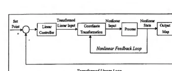
Nonlinear Feedback Loop
[image:22.590.109.459.109.255.2]Transformed Linear Loop
Figure 2.1: The fundamental structure of Partial Feedback Linearization
A control technique where the output y of the dynamic system is differentiated until the physical input u appears in the rth derivative of y. Then u is chosen to yield a transfer function from the "synthetic input", v, to the output y which is:
If, the relative degree is less than n, the order of the system, then there will be internal dynamics. If r = n, then input or output and synthetic input linearization are the same.
2.2 Bang-bang Control
8
2.3 Time-Delayed Control
This method uses the direct and time-delayed signal to cancel the poles of a system with the intention of attenuating the residual vibration. Robust Time-Delayed Control is the method referred to as the proportional plus multiple delay control, involves the use of multiple time delays in conjunction with a proportional part to cancel the dynamics of the system in a robust fashion.
All the above methods start with a parametric input function, which usually involves magnitude and time delay. The parameter values are calculated in order to reduce the residual vibrations at the final position. The speed of the system is determined mainly by the system dynamics and little control can be exercised on the speed of the response. In all cases, the achievement of robustness or the control of vibration leads to an increase in system delays.
2.4 PIC ( Peripheral Interface Circuit )
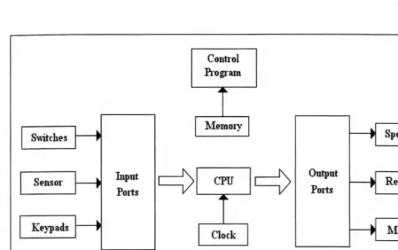
Sensor
Keypads
Input Ports
Control
Program
I
1femory j [image:24.590.66.516.65.347.2]Output Ports
Figure 2.2: Block Diagram for microcontroller
9
The microcontroller is used as a device that can form the basic embedded
system for electronic applications. It provides flexible low-cost solutions to bridge the
gap between single chip computers and the use of large numbers of discreet logic chips.
Depending on various manufactures, microcontroller is divided into several categories
example 8-bit, 16-bit, 32-bit and etc. most commonly used microcontroller is 8-bit
microcontroller. It is simple, small in size and capable of doing most things related with
control and input or output devices.
As for the manufactures, the competitiveness of the microcontroller market has
encourages several big name companies to share a piece of the pie. Those companies
are:
i) Motorola (68HC11, 68HC12)
ii) Intel (8051) iii) Atmel (AVR)