UNIVERSITI MALAYSIA MALAYSIA MELAKA
THE EFFECT OF SINTERING TEMPERATURE AND CLAY
ADDITION ON GLASS CERAMIC PRODUCED FROM
RECYCLED GLASS FOR STRUCTURAL APLLICATION (CIP
METHOD)
This report submitted in accordance with requirement of the Universiti Teknikal
Malaysia Melaka (UTeM) for the Bachelor Degree of Manufacturing Engineering
(Engineering Materials) with Honours.
By
NUR RIFHAN BINTI ROSLI
UNIVERSITI TEKNIKAL MALAYSIA MELAKA
BORANG PENGESAHAN STATUS LAPORAN PROJEK SARJANA MUDA
TAJUK: The effect of sintering temperature and clay addition on glass ceramic produced from recycled glass for structural application (CIP Method)
SESI PENGAJIAN: 2009/10 Semester 1
Saya
NUR RIFHAN BINTI ROSLI
mengaku membenarkan Laporan PSM ini disimpan di Perpustakaan Universiti Teknikal Malaysia Melaka (UTeM) dengan syarat-syarat kegunaan seperti berikut:1. Laporan PSM adalah hak milik Universiti Teknikal Malaysia Melaka dan penulis. 2. Perpustakaan Universiti Teknikal Malaysia Melaka dibenarkan membuat salinan untuk
tujuan pengajian sahaja dengan izin penulis.
3. Perpustakaan dibenarkan membuat salinan laporan PSM ini sebagai bahan pertukaran antara institusi pengajian tinggi.
4. **Sila tandakan (√)
SULIT
TERHAD
√ TIDAK TERHAD
(Mengandungi maklumat yang berdarjah keselamatan atau kepentingan Malaysia yang termaktub di dalam AKTA RAHSIA RASMI 1972)
(Mengandungi maklumat TERHAD yang telah ditentukan oleh organisasi/badan di mana penyelidikan dijalankan)
(TANDATANGAN PENULIS)
Alamat Tetap: No. 23, Jln RU 17,
Tmn Rambai Utama, 75250 Melaka
Tarikh: 23 MAY 2010
Disahkan oleh:
(TANDATANGAN PENYELIA)
Cop Rasmi:
Tarikh: 23 MAY 2010
DECLARATION
I hereby, declared this report entitled “THE EFFECT OF SINTERING
TEMPERATURE AND CLAY ADDITION ON GLASS CERAMIC PRODUCED
FROM RECYCLED GLASS FOR STRUCTURAL APPLICATION (CIP METHOD)”
is the results of my own research except as cited in references.
Signature
: _________________________
Author’s Name
: NUR RIFHAN BINTI ROSLI
APPROVAL
This report is submitted to the Faculty of Manufacturing Engineering of UTeM as a
partial fulfillment of the requirements for the degree of Bachelor of Manufacturing
Engineering (Engineering Materials) with Honours. The member of the supervisory
committee is as follow:
i
ABSTRACT
ii
ABSTRAK
iii
DEDICATION
Dedicated to my father, Rosli Bin Hasan and my mother, Rahmah Binti Nordin
To my supervisor, Dr. Jariah Binti Mohamad Juoi, lecturers and friends for all of their
iv
ACKNOWLEDGEMENT
I would like to convey my thanks to those who have been very helpful in conducting this
project for their favorable advice in finding most solution. Thus, I take this golden
opportunity to express my millions of gratitude to my supervisor, Dr. Jariah Binti
Mohamad Juoi for her kindly advice and guidance during the project; providing
tremendous consideration and useful comments and materials to overcome obstacles that
I had faced. These thanks also dedicate to Associated Professor Dr Thangaraj Joseph
Sahaya Anand and Dr. Azizah Binti Shaaban for their encouragement, fully support, by
providing me enormous guidance and idea for my research project. Also, my special
thanks to Mrs. Norhafizah Binti Ishak, for your time and co-operation completing my
research project. Subsequently to Mr. Mohd Farihan Bin Sabtu and Mohd Azhar Bin
Abu Shah and all technicians involved to complete this project. Special thanks to my
friends for their help during undertaking this project. Thanks are also extended to FKPlecturers who had provided technical help and assistance throughout the project. Lastly I
v
TABLE OF CONTENTS
Abstract
i
Abstrak
ii
Dedication
iii
Acknowledgement
iv
Table of Contents
v
List of Tables
viiii
List of Figures
xi
List of Abbreviations, Symbols, Specialized Nomenclature
xiv
1. INTRODUCTION
1
1.1 Project Background
1
1.2 Problem Statement
3
1.3 Objectives
3
1.4 Scope of project
4
2. LITERATURE REVIEW
6
2.1
Introduction
6
2.2
Recycling Waste
6
2.2.1 Recycling Glass
7
2.2.1.1 Raw Materials
8
i
Composition and Properties of 9Soda Lime Silica Glass (SLSG)
2.3
Glass Ceramic
13
2.3.1 Particle size
15
2.3.2 Processing of Glass Ceramic
16
2.3.2.1 Forming
18
i
Uniaxial Pressing Method
20
vi
2.3.2.2 Densification
22
2.3.2.3 Sintering
22
i
Solid State Sintering
24
ii
Temperature and Time
24
2.3.3 Crystal Phase and Microstructure
25
2.3.4 Analyses and Testing
26
2.3.5 Structural Application and Products
27
3. METHODOLOGY
28
3.1
Introduction
28
3.2
Materials
30
3.2.1 Soda Lime Silica Glass
30
3.2.2 Ball Clays
31
3.3
Samples Preparation
32
3.3.1 Raw Materials Preparation
33
3.3.1.1 Crushing
33
3.3.1.2 Mixing SLSG and Ball Clay Powder
33
3.3.2 Samples Fabrication
34
3.3.2.1 Forming
34
3.3.3 Sintering Process
36
3.4
Analyses
37
3.4.1 Physical Analyses
37
3.4.1.1 Porosity Test
38
3.4.1.2 Density Measurement Test
38
3.4.1.3 Water Absorption
39
3.4.2 Microstructure Analysis
39
3.4.3 Phase Analysis
40
3.5
Mechanical Testing
41
vii
4. RESULTS
43
4.1
Introduction
43
4.2
Observation on Sample Produced
43
4.3
Analyses
47
4.3.1 Physical Analysis
47
4.3.1.1 Porosity
47
4.3.1.2 Bulk Density
49
4.3.1.3 Water Absorption
50
4.3.2 Microstructure Analysis
52
4.3.3 Phase Analysis
56
4.3.4 Microhardness
60
5. DISCUSSIONS
62
5.1
Introduction
62
5.2
Observation on Sample Preparation
62
5.3
Analyses
63
5.3.1 Physical Properties
63
5.3.2 Microstructure
64
5.3.3 Phase
69
5.4
Mechanical Properties
70
6. CONCLUSIONS AND RECOMMENCDATION
72
6.1
Conclusion
72
6.2
Recommendation
74
REFERENCES
75
APPENDICES
79
viii
B
Gantt Chart of PSM II
80
ix
LIST OF TABLES
2.1
The variations of chemical composition of
10
Soda Lime Silica Glass (SLSG)
2.2
Typical viscosities and physical properties of
11
Soda lime Silica Glass (SLSG)
2.3
The comparison between Soda lime Silica Glass (SLSG)
12
with other glasses
2.4
Commercial glass ceramic
14
2.5
Major Compaction Techniques Used for Ceramic fabrication
19
2.6
Techniques for Powder preparation and Sizing of Ceramic Fabrication
20
2.7
Stages of sintering
23
3.1
Physical properties and relevant ASTM Standards of Soda Lime
30
Silica Glass (SLSG)
3.2
The variations of chemical composition of ball clays
32
3.3
Parameters of Sintering Process
36
4.1
Glass ceramic samples at different temperature and different
42
SLSG to ball clay weight ratio
4.2
The porosity percentage of glass ceramic produced at different
47
temperature and different SLSG to ball clay weight ratio
4.3
The bulk density of glass ceramic produced at different sintering
49
temperature and different SLSG to ball clay weight ratio
4.4
The water absorption percentage of glass ceramic produced at different
51
sintering temperature and different SLSG to ball clay weight ratio
4.5
The SEM micrographs for temperature 750
°
C at different SLSG
53
to ball clay ratio at various magnification
x
4.7
The SEM micrographs for temperature 950
°
C at different SLSG
55
to ball clay ratio at various magnification
4.8
The crystal phase of XRD pattern of glass ceramic produced from
56
recycled glass
4.9
Hardness Properties of glass ceramic produced at different sintering
60
temperature and different SLSG to ball clay weight ratio
xi
LIST OF FIGURES
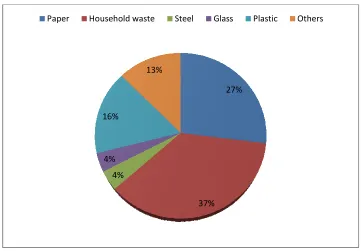
2.1
Breakdown of solid waste created by Malaysians
7
2.2
Classifications of ceramic materials on the basics application
8
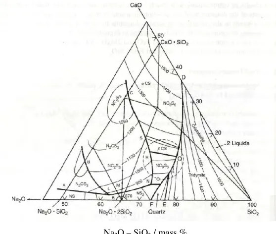
2.3
Phase equilibrium diagram of Na
2O – CaO – SiO
210
2.4
The variation (%) of test result in FG replacement with FA
16
2.5
Schematic of wet bag Cold Isostatic Pressing
21
2.6
The flexible container is (a) filled, (b) submerged, (c) pressed and
21
(d) decompressed before removal
22
2.7
Changes that occur during sintering
23
2.8
XRD spectra of the investigated sintered glass ceramic
25
2.9
SEM images for the glass-ceramics heat-treated at 850
°
C - 1000
°
C
26
3.1
Flow chart of methodology
29
3.2
Soda Lime Silica Glass (SLSG) containers
30
3.3
Ball clays
31
3.4
Powder forming technique of Soda Lime Silica Glass (SLSG)
32
3.5
Hammer
33
3.6
Top Loading Balances
34
3.7
Uniaxial Pressing Machine
35
3.8
Cold Isostatic Press (CIP) Machine AIP3-12-60CPA
35
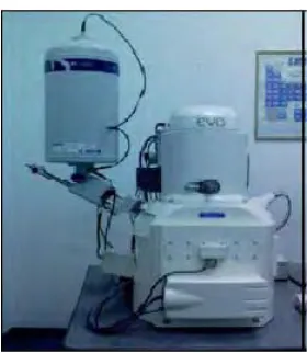
3.9
Scanning Electron Microscopy (SEM) EVO 50
40
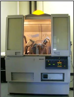
3.10
X-Ray Diffraction (XRD) Machine
41
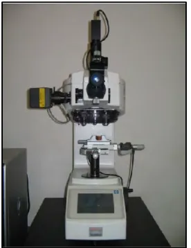
3.11
Microhardness Test Machine
42
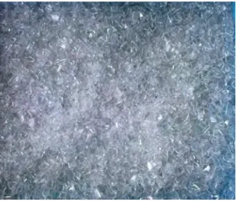
4.1
Soda Lime Silica Glass (SLSG) particles after crushing process
43
4.2
Green pellet of glass ceramic produced at different SLSG to clay
44
weight ratio : (a) 5 wt.% (b) 10 wt.% (c) 15 wt.%
4.3
Glass ceramic sample with 10 mm diameter
45
xii
and different SLSG to ball clay
weight ratio
4.5
Bulk density of glass ceramic produced at different sintering
50
temperature and different SLSG to ball clay
weight ratio
4.6
Percentages of water absorption towards glass ceramic produced
51
at different sintering temperature and different SLSG to ball clay
weight ratio
4.7
XRD patterns of glass ceramic samples at different sintering
57
temperature and different SLSG to ball clay weight ratio at
temperature 750
°
C
4.8
XRD patterns of glass ceramic samples at different sintering
58
temperature and different SLSG to ball clay weight ratio at
temperature 850
°
C
4.9
XRD patterns of glass ceramic samples at different sintering
59
temperature and different SLSG to ball clay weight ratio at
temperature 950
°
C
4.10
Value of microhardness towards glass ceramic produced at different
61
sintering temperature and different SLSG to ball clay
weight ratio
5.1
The SEM micrographs at temperature 950
°
C of glass ceramic samples
65
with 5 wt.% of ball clay addition at the 500x of magnification
5.2
The SEM micrographs at temperature 950
°
C of glass ceramic samples
66
with 10 wt.% of ball clay addition at the 500x of magnification
5.3
The SEM micrographs at temperature 950
°
C of glass ceramic samples
66
with 15 wt.% of ball clay addition at the 500x of magnification
5.4
The SEM micrographs at temperature 750
°
C with 13 h sintering time
67
of glass ceramic samples with 15 wt.% of ball clay addition at the 2000x
of magnification
5.5
The SEM micrographs at temperature 850
°
C with 15 h sintering time
68
of glass ceramic samples with 15 wt.% of ball clay addition at the 2000x
of magnification
xiii
time of glass ceramic samples with 15 wt.% of ball clay addition
at the 2000x of magnification
5.7
The schematic representation of XRD technique towards powdered
70
samples.
xiv
LIST OF ABBREVIATIONS
ASTM
-
American Standard Testing Material
CaCO
3-
Calcium carbonate
CaO
-
Calcium Oxide
CIP
-
Cold Isostatic Pressing
FA
-
Fine Aggregate
FG
-
Fine Glass
K
-
Kelvin
MHz
-
Mega hertz
MPa
-
Mega pascal
Na
2O
-
Natrium Oxide
PVA
-
Polyvinyl Alcohol
SEM
-
Scanning Electron Microscope
SLSG
-
Soda lime Silica Glass
SiO
2-
Silicon Oxide
Tg
-
Transition glass temperature
Tm
-
Melting temperature
Wt. %
-
Weight percentage
XRD
-
X-Ray Diffraction
α
τ
-
Thermal expansion coefficient
µm
-
micro meter
1
CHAPTER 1
INTRODUCTION
1.1
Background of study
Glass ceramic can be defined as a fine-grained crystalline ceramic material that was formed as a glass and subsequently devitrified (Callister W. D., 2005). Nowadays, the used of glass ceramic becomes famous in structural applications as well as in manufacturing industry. The primary advantages of glass ceramic are higher strength, chemical durability, and electrical resistance and can be made with very low thermal expansion coefficients, giving excellent thermal shock resistance (Rahaman M. N., 2003). Throughout its performance, glass ceramic play a vital role in consumer needs or products that exhibits high level of mechanical properties. The main purpose of using recycled glass in glass ceramic is to improve the physical and mechanical properties of existing ceramic materials.
2
In line with the idea to reuse the SLSG to manufacture glass ceramic products, there have several factors that should be considered in order to make it beneficial. Factors such as particle size distribution and fillers used during powder preparation, processing method and sintering process are among crucial factors that should be properly considered. Physical analyses and mechanical testing for the product should also be considered in order to ensure its quality.
Particle size distribution is important, depending on which consolidation or shaping technique is to be used. Low porosity and fine grain size are beneficial to achieve a glass ceramic with high strength (Richerson D. W., 2005). Thus, fine grained size below than 75 µm is going to be employed in this study. The addition of binder and filler will affect the performances and properties of the new material produce from recycled glass. Various types of binders have been used from previous study by the researchers such as polyvinyl alcohol (PVA), ball clays, quartz-feldsphatic sands and others. These binders and fillers are widely used to provide enough strength in the ‘green body’ (unfired compact) to permit handling, ‘green’ machining, or other operations prior to densification (Richerson D. W., 2005). Therefore, the introduction of ball clays as filler has been employed in this study to develop properties which have the precise composition and ratios that give significant affects on some properties.
It is essential to finalize the suitable processing method for this study. In general, pressing method is widely used for forming of ceramic materials. There are various types of pressing techniques such as pressing, slip casting and tape casting. In this study uniaxial pressing and cold isostatic pressing (CIP) is chosen as a method for compaction and shaping of the powder materials into a rigid die body.
3
In this study, Scanning electron microscope (SEM) and x-ray diffraction (XRD) analysis are use to analyze the microstructure and phases present in the samples produced. Physical analysis and mechanical testing are also conducted in order to analyze the properties of the samples.
1.2
Problem statement
4
1.3
Objectives
The objective of this project is:
i. To study the effects of sintering temperature and clay addition toward glass ceramics produced from recycled glass by using Cold Isostatic Pressing (CIP) Method.
ii. To analyze the physical and mechanical properties of glass ceramics samples produced from recycled glass.
iii. To study the microstructure and phases present in the glass ceramics samples produced from and recycled glass.
1.4
Scope of study
The scope of this project is mainly focus on converting recycling glass into glass ceramic product. This study uses soda lime glass as the raw material. The process started by preparing the soda lime glass powder. The powders of SLSG were prepared by crushing raw materials using hammer. The size of particle then was sieved by using the sieve to determine the average particle size.
Next stage of process involves the mixing the raw materials with filler. The use of filler is to bind the materials together while mixtures. The filler that used in this project is ball clays. The chosen of filler is important to improve the strength of the as-formed product to provide strength for handling (green strength) before the product is densified by firing (Reed J. S., 1995).
5
overcome by applying pressure from all direction instead of only one or two directions. Application of pressure from multiple directions achieves greater uniformity of compaction and increased shape capability (Richerson D. W., 2006).
In line with the objectives of this study, the effects of sintering temperature and addition of ball clay are analyzed on the physical and mechanical properties of glass ceramics. Various sintering temperature are used according to the transition glass (Tg) of recycled waste which will result the final product. In this study, there are three sintering temperatures and ratios of SLSG to ball clay are employed.
6
CHAPTER 2
LITERATURE REVIEW
2.1
Introduction
This chapter are discussed the on materials and method which is used in this study. Firstly, this chapter introduce waste glass material and narrows down to type of recycled glass which are used as a raw material. The connection of recycled glass with glass ceramic also will be explained in this chapter. Other than that, the processing of glass ceramic will gives as an image on the method of glass ceramic produced in this study. This chapter end by discussing related research on recycled waste in terms of raw materials, processing and end result focusing on the effects of sintering temperature and clay addition towards glass ceramic produced.
2.2
Recycling Waste
Figure 2.1
(Source: http://www.kpkt.gov.my/kitarsemula
2.2.1 Recycling Glass
The amount of waste glass is gradually increased over the recent years due to an ever-growing use of glass product. Most of the waste glasses have been dumped into landfill sites. The landfilling of waste glasses is undesirable because they are not biodegradable, which makes the environment less (
great concern regarding the waste management issues should be taken in order to reduce the wastes by recycling, which give a lot of benefits to the environment and also to the economy.
According to Callister W. D.
Most ceramic materials fall into an application
groups of glasses, clay products refractories, abrasives, cements and advanced ceramics. Figure 2.2 presents a classification of ceramic materials on the basic application. Glass is a noncrystalline solid which has a transparent surface that has a mixture of materials such as silica, soda ash and
temperature followed by cooling during which solidification occurs without 4%
16%
Paper Household waste
7
Figure 2.1: Breakdown of solid waste created by Malaysians (Source: http://www.kpkt.gov.my/kitarsemula - online on 8 October 2009)
Recycling Glass
The amount of waste glass is gradually increased over the recent years due to an growing use of glass product. Most of the waste glasses have been dumped into landfill sites. The landfilling of waste glasses is undesirable because they are not makes the environment less (Turgut et al., 2009). Therefore a great concern regarding the waste management issues should be taken in order to reduce the wastes by recycling, which give a lot of benefits to the environment and
W. D. (2005), the glasses are a familiar group of ceramics. Most ceramic materials fall into an application-classification scheme that include groups of glasses, clay products refractories, abrasives, cements and advanced presents a classification of ceramic materials on the basic application. Glass is a noncrystalline solid which has a transparent surface that has a mixture of materials such as silica, soda ash and CaCO3 formed by melting at high
rature followed by cooling during which solidification occurs without 27% 37% 4% 4% 16% 13%
Household waste Steel Glass Plastic Others
online on 8 October 2009)
The amount of waste glass is gradually increased over the recent years due to an growing use of glass product. Most of the waste glasses have been dumped into landfill sites. The landfilling of waste glasses is undesirable because they are not 2009). Therefore a great concern regarding the waste management issues should be taken in order to reduce the wastes by recycling, which give a lot of benefits to the environment and
8
crystallization. Glass only has a short-range crystal structure. The bond angles causes the glass structure varies over a range of angles. Glass does not melt at a particular temperature because the variation in bond angles causes the glass structure to soften over arrange of temperatures. The viscosity changes gradually over this range, which allows glass to be formed into a wide variety of products (Haun Labs, 2000). Manufacture products such as sheet glass, bottles, glassware and vacuum tubing in an example of applications of glass.
Figure 2.2: Classifications of ceramic materials on the basics application (Callister W. D., 2005)
In ceramic industry, different kinds of wastes have already been recycled. Wasted glasses have a huge potential for using recycled glass in the structural applications. The products such bricks, tiles and concrete is an example of structural product of ceramic materials. The utilization of wasted glasses can be an alternative way to save energy in the production process and to reduce the manufacturing cost (Vorrada et al., 2009). Incorporation of the wasted glasses into a mixture, results in higher density, less water absorption and lower drying shrinkage of the ceramic products. Therefore, soda lime silica glass (SLSG) is chosen as a raw material in this study depending to it appropriate properties such as low melting temperature, easily worked and durable.
2.2.1.1 Raw materials
9
and food container, structural glass walls, panel glass dismantled cathode ray tubes (CRTs) and white windows glass. Raw material such as SLSG is chosen because it has no significant effect on semi-finished products but it result in firing behavior, increased shrinkage and closed porosity, decreasing open porosity and bulk density and lowering mechanical and tribological performances (Matteucci et al., 2002). Besides to be as a raw material, SLSG also could act as a fluxing agent which resulted in better mechanical characteristics (Vorrada et al., 2009).
In terms of recycled wastes, other than recycled glass, previous study also used industrial wastes such as coal fly ash, mining incinerator residue and lime from fume abatement systems as reagents into stoneware, tiles, bricks and concrete to help lowering firing temperature of glass ceramic products (Vorrada et al., 2009). The influence of adding recycled wastes into glass ceramic products result on the microstructure and mechanical properties in order to obtain new glass ceramic products by powder technology and sintering process (Rozenstrauha et al., 2006). In this study, raw material utilizes is SLSG.
i. Composition and Properties of Soda Lime Silica Glass (SLSG)
SLSG is referred as commercial glass consists mainly of sodium, calcium and silicon oxides (Na2O, CaO and SiO2). The minor constituents of SLSG included alumina,
magnesia and several other oxides. SLSG has the unique combination of low cost raw material with good glass manufacturing characteristics. SLSG generally fall in a narrow range of compositions along the boundary between (Na2O – 3CaO – 6SiO2)
and tridymite (SiO2) in the Na2O – CaO – SiO2 phase diagram. Figure 2.3 shows the
phase diagram of Na2O – CaO – SiO2. This diagram is of particular importance to
10
Figure 2.3: Phase equilibrium diagram of Na2O – CaO – SiO2 (Richerson D. W., 2006)
[image:29.612.187.466.55.291.2]SLSG can be divided technically into two which is glass used for windows and glass used for container. The composition of this both is fairly similar but slight variations in colorants and the ratios of the constituents can have a significant affect on some properties such as thermal expansion and crystallization behavior. If the recycled glass used is from different sources is combined, these variations can cause problems depending on the processing method used. Processing problem from variations in composition can generally be reduced by using finer glass particles (Haun Labs, 2000). The chemical composition of SLSG is lists shown in Table 2.1
Table 2.1: The variations of chemical composition of Soda Lime Silica Glass (SLSG) (Haun Labs, 2000)
Soda Lime Silica Glass (wt. %)
Silica sand SiO2 69 – 74
Lime (calcium oxide) CaO 5 – 14 Soda Na2O 10 – 16
Boron oxide B2O3 -
Potassium oxide K2O -
Magnesia MgO 0 – 6 Alumina Al2O3 0 – 3
Others 0 – 5
11
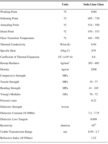
According to Matthias et al., (2008), in contrast to most other materials, glasses do not consist of a geometrically irregular network of crystal but of an irregular network of silicon and oxygen atoms with alkaline parts in between. The composition of chemical gives an important influence on the viscosity, the melting temperature, Tm,
[image:30.612.149.506.233.706.2]and the thermal expansion coefficient, ατ, of glass. Typical viscosities and physical properties of SLSG is mention in Table 2.2.
Table 2.2: Typical viscosities and physical properties of Soda lime Silica Glass (SLSG) (Matthias et al., 2008)
Units Soda Lime Glass
Working Point °C 1040
Softening Point °C 695 – 730
Annealing Point °C 514 – 550
Strain Point °C 470 – 515
Glass Transition Temperature °C 442 – 592
Thermal Conductivity W/(m K) 0.94
Specific Heat J/(kg C) 879
Coefficient of Thermal Expansion 1/C (x10^-6) 8.6
Knoop Hardness kg/mm2 565 - 605
Density kg/cm 2500
Compressive Strength MPa
Tensile Strength MPa 19 - 77
Bending Strength MPa 41 - 165
Young's Modulus GPa 70 - 72
Poisson's ratio 0.22
Dielectric Strength kv/cm
Dielectric Constant (@1MHz) 7.2 - 7.75
Dielectric Loss Tangent 0.009
Resistivity ohm/cm 1010
Usable Transmission Range um 0.50 - 2.7
12
[image:31.612.134.523.189.604.2]The characteristics of SLSG are low melting temperature, easily worked and durable. In applications, SLSG are widely used as such as bottles. Even though there has various colors of bottles, for this study, transparent SLSG bottles are used as raw material. The comparison between SLSG with other glasses is shown in Table 2.3.
Table 2.3: The comparison between Soda lime Silica Glass (SLSG) with other glasses (Matthias et al., 2008)
Glass Composition
(wt. %) Properties Uses
Soda lime silica glass
SiO2 – 70
NaO2 – 15
CaO – 10 Others – 4
Low melting point Moldable into shapes Cheap
Breakable
Can withstand high heat
Glass containers Glass panes Mirrors
Lamps and bulbs Plates and bowls Bottles
Lead glass (crystal)
SiO2 – 70
NaO2 – 20
PbO – 10
High density and refractive index
Glittering surface Soft
Low melting point
Containers for drinks and fruit
Decorative glass and lamps
Crystal glassware Lenses for spectacles
Borosilicate glass (Pyrex)
SiO2 – 80
B2O3 - 13
NaO2 – 4
Al2O3 – 2
Resistant to high heat and chemical reaction
Does not break easily
Allows infra-red rays but not ultra-violet rays
Glass apparatus in laboratories
Cooking utensils
Fused silicate glass
SiO2 – 99
B2O3 - 1
High melting point Expensive
Allows ultraviolet light to pass through
Difficult to melt or mould into shape
13
2.3
Glass Ceramic
Glass ceramic materials are combination of many properties with both glass and more traditional crystalline ceramics. Glass ceramic have no pores between crystals like sintered ceramics. The atomic arrangement of glass is stable at high temperature but not at room temperature. The atoms want to rearrange into a crystalline structure but do not have enough mobility at room temperature (Richerson D. W., 2006). By adding additives when glass is initially formed and by heat treating at a suitable temperature below the melting temperature, the glass can be induced to crystalline. At that temperature, enough energy is present allow the atoms to move. Thus, the atoms in the glass rearrange around the atoms of the nucleating agent to form a polycrystalline ceramic called a glass ceramic.
14
All commercial as well as most experimental glass ceramic are based on silicate bulk glass compositions. Glass ceramic can be further classified by the composition of their primary crystalline phases, which may consist of silicates, oxides, phosphates, borates or fluorides (Ray et al., 2000). Example of commercial glass ceramics are given in Table 2.4.
Table 2.4: Commercial glass ceramic (Ray et al., 2000) Commercial
Identification Crystal Phases Properties Application
Corning 8603 Li2O – 2SiO2, SiO2
Photochemically machinable
Fluid amplifiers, molds for printing printers
Corning 9606 2MgO – 2Al2O3 - 5 SiO2, SiO2, TiO2
Low expansion,
transparent to radar Radomes
Corning 9608 β – spodumene solid solution, TiO2
Low expansion, good chemical durability
Household cooking utensils
Corning 9611 α – quartz solid solution Very high strength Structural members
Neoceram (Japan) β – spodumene solid
solution Low expansion
Household cooking ware
Owens-Illinois
cervit β – quartz solid solution
Zero expansion at ambient temperatures
Telescope mirror blanks
Anchor-Hocking
Cookware β – quartz solid solution Low expansion
Household cooking ware
Corning 0303 Na2O – 2Al2O3 - 2SiO2, BaO – 2Al2O3 - 2SiO2,
High strength Tableware and dinnerware
Corning CYKOL
and CYKO2 Sodium elobate High dielectric constant Miniature capasitors Corning 9690 β – quartz solid solution Low expansion Gas-stove burners
Corning 0333 β – quartz solid solution High strength,
weatherability Building cladding
15
which initiate the crystallization process and influence the particular mix of phases that develops. Commonly, platinum, TiO2, ZrO2 and P2O5 in concentration from 0.01
wt. % to 10 wt. % are used nucleating agents as silicate-based glass ceramics. In order to getting good properties of glass ceramic produced from recycled glass, factors such as particle size and processing is a significant with better result in crystal phase and microstructure, physical analysis and mechanical testing.
2.3.1 Particle size
Measurement of particle size distribution is key for characterizing a ceramic powder. Particle size is important depending on which consolidation or shaping technique is to be used. In the previous study, the objective of consolidation step is to achieve maximum particle packing and uniformity, so that minimum shrinkage and retained porosity will result during densification. Turgut et al., (2009) revealed that the replacement fine glass (FG) with fine aggregate (FA) at level of 20 % by weight had a significant effect on properties of glass ceramic samples. Figure 2.4 shows the variation percentage of test results in FG replacement with FA.
Figure 2.4: The variation (%) of test result in FG replacement with FA (Turgut et al., 2009)
16
(2005) study in determined the temperature and time at temperature necessary to achieve sintering.
2.3.2 Processing of Glass Ceramic
The processing of glass ceramic is similar with the processing of ceramics. There are various processing method that are used to produce glass ceramic materials. According to previous study, most of the researchers paid much attention on the sintering behavior of glass ceramic produced. The processing method in Matteucci et al., (2002) started by mixed the soda lime float and food container with glass ceramic product which is porcelain stoneware. The weight percent of recycled glass is 5 wt. % and 10 wt. %. The mixture then continues with normal process and end by sintering process. Differ with Vorrada et al., (2009), which after the mixing process, the mixture will then soaked, stirred and kneaded to formed for 1 day before fired in furnace at temperature 1000 °C – 1200 °C and finished by cooled down at room temperature.
Any other different techniques from Bernardo et al., (2007) study, which the mixture of raw material and mining residue is investigated using X-ray Diffraction (XRD) before treated at 1350 °C for 2 hours until the glass melted and poured on steel plates. The drastic cooling forced the samples into a number of fragments before milled using ball mill and sized to a dimension of 37 µm. Process continues with sintered the samples at 960 °C for 30 minutes and done drying treatment at 120 °C before end out by pressed again at 40 MPa. Techniques from Bernardo et al., (2007) is a fast treatment to the sample product to ensure the mixture of industrial waste has been successfully transformed into dense and strong sintered glass ceramic with short holding times and a very rapid heating.
17
Kelvin (K) for 2 hours. Samples the placed on the alumina bricks and heated at 10 K / min to the maximum nucleation temperature and soaking for 15, 30 and 60 min for crystallization and then were cooled in furnace.
Another different processing technique done by Bernardo et al., (2005) which started the processing with mixed in the proportion panel glass dismantled, lime and residues 28 % - 25 % - 47 % by weight. The mixtures of A, B and C were dry ball milled and sized to grains below than 88 µm for coarse powders and below 37 µm for finer powder. Samples then were gently pressed in rectangular die and sintered in air at the crystallization temperature for 1h to 5h with a heating rate of 10 °C min.
The processing by Minoru et al., (2004) begun with weight 30g of each samples and placed in covered alumina crucible. Samples were then heated at 10 K / min to 1400
°C in siliconit furnace and then kept the samples at 1450 °C for 2h. After refining 1300 °C for 1h and the melts were poured onto an iron plate before heat treated at 900 °C to 1200 °C for 1 to 4 h. This study focused more on the crystalline phase of glass ceramic produced.
Turgut et al., (2009) carried out different technique of processing dry mixed the white windows glass with constant proportions of cement for 1 min and mixed with water for 3 min before poured in molds and force at 17 MPa is applied for 1 min. samples are then removed from molds and cured under the water for 28 days. Then, the samples are dried for 24 h using ventilated oven at 105 °C and weight at room temperature.
18
sintered in air with heating rate was 8 °C / min between sintering temperature 1000
°C and 1120 °C. The technique used is same which is started with powder preparation, forming and end by sintering differ with other techniques which used different processing even tough the end result of each study is to producing glass ceramic samples from recycled glass.
Processing of glass ceramic usually made in three steps which are forming a powder to desired shape, partially drying and firing at high temperature to produces dense product.
2.3.2.1 Forming
19
Table 2.5: Major Compaction Techniques Used for Ceramic fabrication (Richerson D. W., 2006)
Technique Example Pressing Uniaxial Isostatic Hot Pressing
Hot Isostatic Pressing Slip Casting Drain casting
Solid casting Vacuum casting Pressure casting Centrifugal casting Fugitive – mold casting Gel casting
Electrophoretic deposition Tape Casting Doctor blade
Waterfall Plastic Forming Extrusion
Roll forming Injection molding Compression molding
20
Table 2.6: Techniques for Powder preparation and Sizing of Ceramic Fabrication (Richerson D. W., 2006)
Mechanical Chemical Miscellaneous Screening Elutriation Air classification Ball milling Attrition milling Vibratory milling Turbomilling Fluid energy milling Hammer milling Roll crushing Precipitation Sol-gel Liquid mix Decomposition Freeze drying Hot kerosene drying Plasma
Laser
Hydrothermal
Calcining
Fluidinized bedRotary kiln Combustion synthesis
According to Reed J.S. (1995), pressing is the most widely forming process to produced parts. Products produced by pressing include ceramic tile and porcelain products, coarse grained refractories, grinding wheels and structural clay products. Pressing by means of punches in hardened metal dies, commonly called uniaxial pressing, is widely used for pressing parts thicker than 0.5 mm and parts with surface relief in the pressing direction. Isopressing, commonly known as isostatic pressing were used flexible rubber molds. Isostatic pressing is used for producing shapes with relief in two or three dimensions, shapes with one elongated dimension such as rods and tubes, and vey massive product with a thick cross section. Both of uniaxial pressing and isostatic pressing have wet and dry bag. In this study, dry bag isostatic pressing is used in order to produce new type of glass ceramic materials.
i. Uniaxial Pressing Method
21
ii. Cold Isostatic Pressing (CIP) Method
There are two kind of isostatic pressing which is wet and dry bag. In both bags, the press mix is placed in an elastomer bag and compacted with hydraulic pressure on the exterior of the bag (King A. G., 2002). In this study, wet bag cold isostatic pressing is used to compact the mixture of raw materials and filler. Dry isostatic pressing was developed to achieve increased production rate and close dimension tolerances. The internal parts of wet bag cold isostatic pressing are shown in Figure 2.5.
Figure 2.5: Schematic of wet bag Cold Isostatic Pressing
(Source: http://www.designinsite.dk/htmsider/pb1007.htm - online on 5 October 2009)
22
Figure 2.6: The flexible container is (a) filled, (b) submerged, (c) pressed and (d) decompressed before removal (Winter et al., 2005)
2.3.2.2 Densification
Densification is the next stage of glass ceramic processing. Densification is also known as compaction. Ceramic powders are commonly compressed in a die to produce near net shape green bodies prior to final sintering. Density gradients in the resulting compacts may cause distortions in the shape of the parts during sintering processing to obtain the desired final shape (Reed J. S., 1995).
2.3.2.3 Sintering
Sintering maybe considered as a process by which an assembly of particles, compacted under pressure or simply confined in a container, chemically bond themselves into coherent body under the influence of an elevated temperature. The temperature is usually below the melting point of the major constituent (Upadhyaya
et al., 1998).
23
last stage before the end product produced (Richerson D. W., 2006). Table 2.7 represent the stages of sintering while Figure 2.7 shown the changes that occur during sintering. The differences of sintering temperature affect the end properties of the final products.
Table 2.7: Stages of sintering (Richerson D. W., 2006) Stages of sintering Changes
1st stage (initial) Rearrangement Neck formation 2nd stage (intermediate) Neck growth
Grain growth High shrinkage Pore phase continuous 3rd stage (final) Much grain growth
Discontinuous pore phase Grain boundary pores eliminate
Figure 2.7: Changes that occur during sintering (Richerson D. W., 2006) (d)
(g)
(f) (e)
24
i. Solid State Sintering
The sintering process involves heating material formed by the compaction at ambient temperatures of pure fine particles (usually below than 1 µm diameter). At high temperatures, typically from 0.5 to 0.8 of the absolute melting temperature, the particles sinter together. This is a spontaneous process and must thus be accompanied by a decrease in free energy of the sample. The most important driving force for sintering is the reduction in solid/vapor surface area when the individual particles fuse together and the larger particles grow at the expense of smaller ones.
Idealized solid state sintering is of restricted practical use for ceramics in those pure materials and fairly high temperatures are involved. Solid sintering does, however, have important applications, and it is possible to obtain solid material close to theoretical density. The resulting comprises individual crystallites or grains, separated by grain boundaries, and probably residual porosity. The grain size is usually much greater than the original particle size (Davidge R. W., 1979).
ii. Temperature and Time
25 2.3.3 Crystal Phase and Microstructure
The structures of glass ceramic usually investigated using x-ray diffraction (XRD) and scanning electron microscope (SEM). Tanaka et al., (2005) pointed out that wollastonite (CaO – SiO2) and anorhite (CaO – Al2O3 - SiO2) are prismatic crystal
structures that have the suitable properties for construction materials. Bernardo et al., (2007) demonstrates in Figure 2.8 that the crystallization of glass occurred even for a very short holding time of 30 min at 960 °C. Three main crystal phase, consisting wollastonite, pseudo-wollastonite and Na-exchanged anorhite were formed.
Figure 2.8: XRD spectra of the investigated sintered glass ceramic (Bernardo et al., 2007)
26
Figure 2.9: SEM images for the glass-ceramics heat-treated at 850 °C - 1000 °C (Park et al., 2007)
For all the processing conditions the microstructure of sintered glass ceramic consist a number of randomly distributed fibrous crystals. The microstructure will change in addition with other binder such as clay to formation of Na-exchanged anorhite, instead of pseudo-wollastonite, leading to improvements in the mechanical properties of glass ceramic produced (Bernardo et al., 2007).
2.3.4 Analyses and Testing
27
In relation to mechanical properties, the strength of glass ceramic samples depends greatly on the amount of wasted glass. The compressive strength, modulus of rupture, hardness gives better result by adding recycled waste into glass ceramic samples. The compressive and modulus of rupture decreased as the recycled wastes increased. The hardness value of glass ceramic samples increased with increase in crystallization degree (Erol et al., 2009).
Final testing of glass ceramic produced will carried out in order to identify the end properties. Commonly, the physical and mechanical testing for glass ceramic produced from recycled glass has improved much better than standard glass ceramic. Testing will be determined in terms of the physical and mechanical properties of glass ceramic samples to ensure samples could be good candidates for industrial use in structural application.
2.3.5 Structural Application and Products
There are only ten percent of the advanced ceramic are used for structural ceramics (Matthias et al., 2008). However, this share is expected to grow. There is a great interest in using glass ceramic in structural application due to high modulus and hardness, low density and resistance to high temperature.
28
CHAPTER 3
METHODOLOGY
3.1 Introduction
This chapter explained the component of the processes involved in the whole scope of study. This includes the description of raw material, sample preparation, sample fabrication, physical properties, analyses of microstructure and phase as well as mechanical testing. The raw materials that involved in this study are recycled soda lime silica glass (SLSG) and ball clays as filler. At the beginning, the composition and properties of SLSG are fully characterized. The recycled SLSG and filler are mixed and appropriate compositions between these both were described.
The mixed SLSG and filler are pressed by using uniaxial pressing machine and CIP machine before proceeds with sintering process. At sintering process stage, there have a three different temperature in order to find out the suitable best sintering temperature to the material produced. The effects of this sintering temperature are carried out. Physical study on the glass ceramic produced also had done in order to test the suitability of the glass ceramic to be use in any structural application. Porosity testing, density measurement and water absorption based on ASTM C373 will be conducted. Further studied on the analysis and mechanical testing are proceed after sintering process. In overall, for analysis testing, the microstructure and phase analysis are examined by Scanning electron microscope (SEM) and x-ray diffraction (XRD) analysis.
29
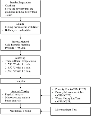
[image:48.612.157.541.137.622.2]evaluated. In overall, the over view of experimental technique and works is simplified as referred to the flow chart in Figure 3.1.
Figure 3.1: Flow chart of methodology
Mixing
- Mixing raw material with filler - Ball clay is used as filler
Process Method - Cold Isostatic Pressing - Pressure = 40 MPa
Sintering
- Three different temperatures 1. 750 °C with 1 h hold 2. 850 °C with 1 h hold 3. 950 °C with 1 h hold
Samples
Analysis Testing - Physical analysis - Microstructure analysis - Phase analysis
Mechanical Testing
- Porosity Test (ASTM C373) - Density Measurement Test
(ASTM C373)
- Water Absorption Test (ASTM C373)
- Microhardness Test Powder Preparation
- Crushing
30
3.2 Materials
The materials employed in this study are recycled soda lime silica glass (SLSG). SLSG will be converted into fine glass particles before mixed with filler. Ball clays are used as filler in this glass ceramic processing.
3.2.1 Soda Lime Silica Glass (SLSG)
Soda lime silica glass (SLSG) obtained from recycled container such as soy bottles, beverages bottles and sauce bottles which is transparent. The SLSG type used was shown in Figure 3.2 and Table 3.1 lists the basic physical properties and relevant ASTM Standard of the SLSG.
Figure 3.2 : Soda Lime Silica Glass (SLSG) containers
Table 3.1: Physical properties and relevant ASTM Standards of Soda Lime Silica Glass (SLSG) (Ray et al., 2000)
Physical properties Value Unit ASTM Standard
Density 2.49 g/cm3 C373
Porosity 0 % C373
Hardness 230 kg/mm2 -
31
Size of glass particles influences the result of end product. The particles size affects the physical properties of strength, toughness and hardness. Thus, finer glass particles, the properties of end product are much better. In this study, the size of glass particles chosen is < 75 µm. These particles are sieved first using sieve with size of 75 µm.
3.2.2 Ball Clays
Ball clays are an additive that added to provide enough strength after the sintering process to permit handling or other operations prior to densification. The main utility of ball clay is its plasticity and it is mixed with non-plastic or less plastic clays to make them obtain the requisite plasticity. The high plasticity of ball clay is attributed to the fact that it is fine-grained and contains a small amount of montmorillonite. Ball clays are chosen as binder mainly due to its contribution of workability, plasticity and strength to the bodies in drying. Figure 3.3 represent the ball clays filler that are used for this study and Table 3.2 illustrated the ball clays compositions.
32
Table 3.2: The variations of chemical composition of ball clays (Worrall W. E., 2006)
Oxide Range of variation (wt. %)
SiO2 40 – 60
Al2O3 25 - 40
Fe2O3 0.25 – 4.0
Na2O 0 – 0.75
K2O 0.5 – 4.0
3.3
Samples Preparation
Samples preparation in this study are carried out as show in the experimental flowchart shown in Figure 3.4. It starts with raw material preparation followed by forming, drying and sintering process.
Figure 3.4 : Powder forming technique of Soda Lime Silica Glass (SLSG)
Raw Material Preparation (Soda Lime Silica Glass (SLSG)) - Crushing
- Mixing
Forming - Uniaxial Pressing - Cold Isostatic Pressing
Method
Green Compact
Sintering 1. 750 °C with 1 h hold 2. 850 °C with 1 h hold 3. 950 °C with 1 h hold
Samples
33
3.3.1 Raw Materials Preparation
3.3.1.1 Crushing
At early stage of raw materials preparation, the raw material which is recycled SLSG were crush manually by using hammer before sieve the SLSG powder < 75 micron by using siever. Same as the ball clay, the powder are sieved to achieve the fineness of < 75 micron. The containers such as bottles are crushed roughly using hammer as depicted in the Figure 3.5.
Figure 3.5: Hammer
3.3.1.2 Mixing of SLSG and ball clay powder
34
Figure 3.6: Top Loading Balances
3.3.2 Samples Fabrication
3.3.2.1 Forming
Figure 3.8
Pressing process initiated by enter 1 gram content of mixture powder into the mold and then press with uniaxial pressing machine with pressure of 40 MPa or about 3.5 tonne. This process takes approximately 10 mi
ceramic. While pressing, each step is done according to proper procedures to avoid sample broken when released. However, for 100 percent powder SLSG, work emphasis can not be done because the links in the powder are not
when removed from the mold. Similarly with the powder which has a ratio of 95: 5, although the ratio is still acceptable but the bonds between the powder of SLSG and
35
Figure 3.7: Uniaxial Pressing machine
8: Cold Isostatic Press (CIP) Machine AIP3-12-60CPA
36
ball clay is not so strong. So, it is not possible if the results produced from the mold are not as beautiful as the sample produced with the ratio of 90: 10 and 85: 15. The sample produced was in pellet shape which is cylindrical shape, the ball clay helps the pellet shaped nicely because the more ratio of ball clay added into the SLSG powder, the pellet shape are more easier to produced. Because there have three different temperatures at the sintering process, in each ratio, 5 samples produce making the total number of samples produced are 45.
For samples that have passed pressing process using uniaxial pressing machine, samples was inserted in the rubber before placed in the CIP machine. Only one sample was added in a rubber. The purpose of sample added in the rubber is to prevent it being contaminated by the liquid when the isostatic pressure was applied to the sample. Pressure used for this process is 40 MPa or 5801 psi. This process takes about 10 seconds to complete pressing of one sample. Basically, after this process the uniformity of the glass ceramic are tougher and not fragile compared to the glass ceramic produced by uniaxial pressing machine.
3.3.3 Sintering Process
The modification of sintering temperature was carried out inclined with the objective of this study. The determination of different sintering temperature is by known the melting point (Tm) and glass transition (Tg) of SLSG. In this study 750 °C, 850 °C
and 950 °C are chosen as sintering temperature with 1 h holding time. Table 3.2 simplified the parameters involved in the sintering process.
Table 3.3: Parameters of Sintering Process
Pressure (MPa) Temperature (°°°°C) Holding time (h)
40 750 1.0
40 850 1.0
37
Sintering process is done in three different temperatures. For each parameter, a total of 15 samples included in the furnace which 5 sample from each of ratio. While in the furnace, the temperature increase is 2 degree / minute for all three temperatures.
3.4
Analyses
For physical analysis, there are three main analyses which are porosity test, density measurement test and water absorption test. Microstructure analysis is to analyze the microstructure using SEM and the phase analysis is to characterize the crystallographic structure in the sample in the glass ceramic produced by using XRD. 9 samples are provided for each analysis which sample represent for each ratio and temperatures.
3.4.1 Physical analyses
There are three main analyses which are porosity, density measurement and water absorption. 9 sample of glass ceramic produced by according to ASTM C 373. At the beginning of this analysis, all samples are dried in an oven at 150°C for 15 minutes and then cooled in the dessicator for 15 minutes. Value for dry mass, D, obtained by weighted samples using top loading balance to the nearest 0:01 g.
Then, samples are boiled in distilled water for 5 h in immersed condition in the water all the time by using wire to separate the sample from bottom and sides of the beaker as well as each other. After boiled for 5 h, the sample is left soaked in distilled water for 24 h. Value for mass, S, glass ceramic samples were weighed after the impregnation process with the mass nearest to 0:01 g. Weighing process performed in a sample loop and tied with wire suspended in the water. Before actually weighing, counterbalance the scale with the wire loop in place and immersed in water to the same depth as is used when the sample are in place.
38
samples. Once completed, the calculation for the amount of apparent porosity, bulk density and water absorption identified with the assumption that 1 cm3 of water weighs 1g.
3.4.1.1 Porosity
Porosity is main problem that occurred to the ceramic materials. The porosity of glass ceramic produced are tested accordance to ASTM C 373. Other than pores, this testing should able to detected cracks or other voids that might be present in the samples produced. This test carried out three test specimens for each different temperature and ratio of SLSG to ball clay. The percentage apparent porosity are calculated by using the following formula;
P (%) = [ (M – D) / V ] x 100 (3.1)
where :
P = percentage of apparent porosity M = saturated mass
D = dry mass V = volume
3.4.1.2 Density Measurement
Density measurement test is used to determine the density of glass. The density measurement of glass ceramic produced was known as a bulk density. This test were conducted accordance to ASTM C 373. The bulk density was measure by divided the sample dry mass with exterior volume. The exterior volume determine by saturated mass minus mass after impregnation process. The true density of the samples is identified through this testing. The bulk density, B, of specimens is calculated by divided dry mass, D, with the volume, V as mention in Equation 3.2.
39 where :
B = bulk density
3.4.1.3 Water Absorption
This test was carried out inclined with the limitations of samples towards resistance to water absorption. Thus, this study was conducted purposely to determine the water absorption behavior of glass ceramic. This test was performed in accordance to the ASTM C 373 the standard test method for water absorption of ceramic materials. Three specimens also provided for this analysis and the percentage of water absorption will be calculated by using the following formula;
A (%) = [ ( M – D ) / D ] x 100 (3.3)
where :
A = percentage of water absorption
3.4.2 Microstructure analysis
The microscopy study of glass ceramic produced was measured under the Scanning Electron Microscopy (SEM) EVO 50 (Carl Zeiss SMT, UK) as represent in the Figure 3.9. Analysis was carried out to investigate the microstructural features on the surface of the glass ceramic produced. The surface of glass ceramic sample to be examined is scanned by electron beam and reflected beam of electrode is collected, and then displayed at the same scanning rate on a cathode ray tube which represents the surface features of the glass ceramic produced.
40
[image:59.612.257.397.190.351.2]For the preparation, the glass ceramic produced is coated with gold prior to examination. The type of SEM signals used is secondary electron which has interactions between electron beam and atom at or near the surface of the sample. Four magnifications were used 500x, 1000x, 2000x and 3000x at the same area to view the microstructure more clearly.
Figure 3.9: Scanning Electron Microscopy (SEM) EVO 50
3.4.3 Phase analysis
41
Figure 3.10: X-Ray Diffraction (XRD) Machine
3.5
Mechanical Testing
3.5.1 Microhardness Test
42
Figure 3.11: Microhardness Test Machine
43
CHAPTER 4
RESULTS
4.1
Introduction
This chapter covers the observations and results achieved throughout this study. This include observation during sample preparation upon mixing Soda Lime Silica Glass (SLSG) and ball clay, characterization of the glass ceramic produced (microstructure and phase), physical analyses and microhardness test.
4.2
Observation on Sample Produced
During the sample preparation, all the observation is inform clearly starting with powder preparation which include sieving, mixing and weighing process of the mixture powder of SLSG and ball clay. Figure 4.1 shows SLSG particles after the crushing process. Figure 4.2 shows pellets of samples produced after Cold Isostatic Pressing (CIP) the result of powder after pressing process.
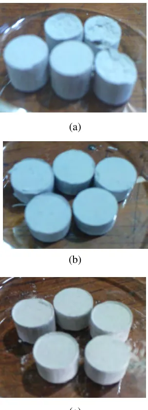
[image:62.612.243.413.553.698.2]Figure 4.2: Green pellet of glass ceramic produced at different
Sample produced from pressing process
surface finish is observed to be affected by the total percentage of ball clay in SLSG powder. The greater percentage
produced more compact pellet and good surface finish. produced with a diameter of 10 mm
for each temperature with different
44 (a)
(b)
(c)
pellet of glass ceramic produced at different SLSG to clay weight ratio (b) 10 wt.% (c) 15 wt.%
Sample produced from pressing process is in cylindrical shape or pellets form. surface finish is observed to be affected by the total percentage of ball clay in SLSG
reater percentages of ball clay (5 wt.%, 10 wt.% and 15 wt.%) produced more compact pellet and good surface finish. Figure 4.3 show
produced with a diameter of 10 mm and Table 4.1 shows the result of sample shape for each temperature with different SLSG to ball clay ratio.
to clay weight ratio : (a) 5 wt.%
[image:63.612.249.401.60.481.2]Figure
Table 4.1: Glass ceramic samples at different temperature and different SLSG to ball clay weight ratio
Weight ratio
SLSG glass to
ball clay
(wt.%)
750°°°°
95:5
90:10
85:15
45
Figure 4.3: Glass ceramic sample with 10 mm diameter
Glass ceramic samples at different temperature and different SLSG to ball clay weight ratio
°°°°C 850°°°°C 10 mm
Glass ceramic samples at different temperature and different SLSG to ball clay weight ratio
[image:64.612.105.552.296.721.2]46
Sintering process is done in three different temperatures and different SLSG to ball clay weight ratio. Generally, when the temperature increases, glass ceramic samples are change in terms of color and appearance. The color of brownish samples becomes lighter when the rises of temperature. For the appearance, the glass ceramic samples look glazy and shiny when the temperature increases. For example, at each temperature the colors of samples change from brownish to light brown. This changes of color can seen obviously at 85:15 wt.% of SLSG to ball clay for each temperature. Another observation that can be seen clearly is in term of surface finish for each temperature. At lower temperature 750°C, samples have bad surface finish but at higher temperature give good surface finish. However this trends is not applied to sample produced at 85:15 wt.% ratio of SLSG to ball clay. At this ratio, the glass ceramic samples for each temperature are in good cylindrical shape but at lower temperature there is no glazy and shiny at the surface of samples. This situation can be seen drastically where no glazy surface appear at each ratio at temperature 750°C. The glazing and shining surface happen at the higher temperature.
47
Thus at sintering process, when more high temperature is used; it produced the brighter color displays and glazier surface. This proves that the temperature and SLSG to ball clay ratio plays an important role during the sintering process.
4.3
Analyses
Analyses conducted involved physical analysis (porosity, density measurement and water absorption), microstructure analysis and phase analysis.
4.3.1 Physical Analysis
Results of each physical analysis are shown in section 4.3.1.1 (Porosity), section 4.3.1.2 (Bulk Density) and section 4.3.1.3 (Water Absorption).
4.3.1.1 Porosity
Table 4.2 shows the value of porosity at each glass ceramic samples that obtained from the analysis. The porosity of the glass ceramic produced was measured as a percent, in relationship of the volume of the open pores of the samples to its exterior volume.
Table 4.2: The porosity percentage of glass ceramic produced at different temperature and different SLSG to ball clay weight ratio
Porosity percentage (%)
Ratio SLSG to Ball Clay Weight Ratio
(wt.%) 750°°°°C 850°°°°C 950°°°°C
95:5 1.36 1.68 2.09
90:10 1.10 1.24 1.03
85:15 0.71 0.41 0.40
48
temperature has low percentage of porosity while the highest temperature has greater percentage of porosity at 95:5 wt% ratio of SLSG to ball clay. The maximum percentage of porosity (2.09 %) and the minimum percentage of porosity (0.40%) occurred at the same temperature 950°C. From the result, the percentage of porosity tends to decrease when the temperature increase. This trend happens at temperature 850°C and 950°C but it is not really applied at temperature 750°C. At that temperature, it has the minimum percentage of porosity occurred at 95:5 wt.% ratio of SLSG to ball clay and