DESIGN AND DEVELOPMENT OF AN AUTOMATIC WIPER RETRACTOR SYSTEM
SELVERAJ A/L SUBRAMANIAM
I hereby approve have read this thesis submitted to the senate of UTeM and have accepted this thesis as partial fulfillment of the requirements for the degree in Bachelor
of Mechanical Engineering (Automotive).
Signature :
DESIGN AND DEVELOPMENT OF AN AUTOMATIC WIPER RETRACTOR SYSTEM
SELVERAJ A/L SUBRAMANIAM
This report is submitted in partial fulfillment of the requirement for the Bachelor of Mechanical Engineering (Automotive)
Faculty of Mechanical Engineering Universiti Teknikal Malaysia Melaka
DECRALATION
I hereby, declare this thesis entitled
“THE DESIGN AND DEVELOPEMNENT OF NEW WIPER RETRACTOR” is the results of my own research except as cited in the reference.
Signature :
iii
DEDICATION
ACKNOWLEDGEMENTS
It gives me the greatest pleasure to express my sincere gratitude to my supervisor, Mr. Mohd Zakaria Mohammad Nasir of which we had an excellent working relationship, and who offered tremendous help and encouragement throughout the course of my graduate studies and completion of this project.
In addition, I would also like to thank and show appreciation to Mr Faizul Akmar and whose advice and critic have helped me much in the success of my project.
Thanks also to Universiti Teknikal Malaysia Melaka for giving me the opportunity to complete my degree program successfully and providing help financially to buy the materials required to complete the project.
I would also like to take this opportunity to thank my family members who inspired and supported me throughout the completion of my project.
v
ABSTRACT
ABSTRAK
vii
TABLE OF CONTENT
CHAPTER SUBJECT PAGES
DECLARATION ii
DEDICATION iii
ACKNOWLEDGEMENT iv
ABSTRACT v
ABSTRAK vi
TABLE OF CONTENT vii
LIST OF TABLE xi
LIST OF FIGURES xii
LIST OF SYMBOL xiv
LIST OF APPENDICES xv
CHAPTER I INTRODUCTION 1
1.1 Introduction 1
1.2 Problem Statement 1
1.3 Objective 2
1.4 Scope 2
1.5 Expected Results 3
CHAPTER SUBJECT PAGES
CHAPTER II LITERATURE REVIEW 4
2.1 Background of Project 4
2.2 Understanding the Wiper System 6
2.2.1 Functional Requirements 6
2.2.2 Wiper Blades 7
2.2.3 Wiper Linkages 8
2.2.4 Wiper Motors 9
2.3 Basic Electrical Theory and Electronic Devices 10 2.3.1 Electrical Circuits and Switches 10 2.3.2 Basic Electrical Equivalent 11 2.4 Introduction to Direct Current (DC) Motor 12 2.4.1 DC Motor Operating Principles 13
2.5 DC Motor Characteristics 15
2.5.1 Background from Physics 15
2.5.2 Motor Characteristics 16
2.5.3 Power/torque and Power/Speed Curves 18
2.6 Relay 19
2.6.1 Type of Relay 20
ix
CHAPTER SUBJECT PAGES
CHAPTER III METHODOLOGY 22
3.1 Methodology Flow Chart 22
3.1.1 Detail Description of Flow Chart 24
3.2 Software Description 26
3.2.1 CATIA V5R10 26
3.2.2 Solid Work COSMOS 26
3.3 Experiment and Measurement 27
3.3.1 Load on Wiper 27
3.4 Concept Design 29
3.4.1 Early Sketch 30
CHAPTER IV RESULT 33
4.1 Circuit Overview 33
4.1.1 Schematic Diagram 34
4.1.2 Operating Principal 35
4.2 Retractor Design Stage 36
4.3 Retractor Assembly 37
4.3.1 Retractor Exploded View 38
4.4 Power Window Motor 39
4.4.1 Load Calculation 40
4.4.2 System Testing 41
4.5 Retractor 42
4.5.1 Moving Block 42
4.5.2 Block Housing 43
4.5.3 Threaded Shaft 43
CHAPTER SUBJECT PAGES
4.7 Working Model 45
4.8 Retractor in Action 46
4.9 Costing 48
CHAPTER V DISCUSSION 50
5.1 Product Analysis 50
5.1.1 Analysis Step 50
5.1.2 Stress Von Misses 52
5.1.3 Displacement Analysis 53
5.1.4 Strain Analysis 54
5.2 Problem Encountered 55
5.2.1 Design 55
5.2.2 Material Selection 57
5.2.3 Technique 57
5.2.4 Costing 57
CHAPTER VI CONCLUSION AND RECOMMENDATION 58
6.1 Conclusion 58
6.2 Recommendation 59
REFFERENCES 60
xi
LIST OF TABLES
NO. TITLE PAGES
4.1 Design Selection Criteria 37
4.2 Circuit Costing 48
5.1 Material property of aluminum alloy 1060-H14 51
NO. TITLE PAGES
1.1 Wiper Blade 2
2.1 Windshield Washer Technique 7
2.2 Wiper Blade and Its Parts 7
2.3 Wiper Linkage and Motor 9
2.4 Conventional Circuit Diagrams 11
2.5 Sample Motor 12
(Silver Maxon Motor 2.007)
2.6 DC Motor Operating Principles 14
2.7 Relationship between Torque and Force 15
2.8 Angular Velocity in Motor 16
2.9 Graph of Torque versus Rotational Speed 17 2.10 Graph of Torque versus Rotational Speed (DC motor) 18 2.11 Graph of Torque and Power versus Speed 19
2.12 Relay Circuit 19
3.1 Methodology Flow Chart 23
3.2 Force Measurement Position 28
3.3 Existing Retractor 30
3.4 Stapler Concept 30
3.5 Rack and Pinion Concept 31
xiii
NO. TITLE PAGES
4.1 Forward Reverse Circuit 33
4.2 Schematic Diagram 34
4.3 Retractor Design Stage 36
4.4 Retractor Assembly 37
4.5 Exploded View 38
4.6 Power Window Motor 39
4.7 Motor Spec 39
4.8 Testing 41
4.9 Moving block 42
4.10 Block Housing 43
4.11 Threaded Shaft 43
4.12 Hanger 44
4.13 Working Model 45
4.14 Retracted and Extended Condition 46
4.15 Retractor in a Car 46
4.16 Retractor in Extended Position 47
5.1 Von Misses Stress Analysis 52
5.2 Displacement Analysis 53
5.3 Strain Analysis 54
LIST OF SYMBOL
ECU = ELECTRONIC CONTROL UNIT
F = Force
T = Torque
R = radius
T = time
V = voltage, V
I = current, A
R = resistant, Ohm
D.C = Direct current
= angular velocity, rad/s
τ
=
torque, NP = Power, Watt
NO = Normally Open
NC = Normally Closed
SPST = Single Pole Single Throw DPST = Double Pole Single Throw
DPDT = Double Pole Double Throw
QPDT = Quadruple Pole Double Throw
xv
LIST OF APPENDICES
NO. TITLE PAGES
A Gantt chart PSM 1 61
B Gantt chart PSM 2 62
C Power Window Motor Spec 63
D Detail Drawing of Retractor 64-67
E Aluminum Property 68
F Stress Analysis 69
CHAPTER I
INTRODUCTION
1.1 Introduction
The main purpose of this report is to develop a wiper retractor device which can retract/extend automatically with the touch of a button/switch. Wiper is an important element in a vehicle that functions to wipe rain drop and dirt from windscreen. Wipers are also used in other vehicles, such as buses, trams, locomotives, aircraft and ships.
1.2 Problem Statement
The problem that brought the idea of developing a new wiper retractor system is the weariness of the rubber of the wiper which cleans the windscreen from moist and dirt. The rubber blade tends to lose its quality due to too much exposure to sun light. The contact between rubber and windscreen during the hot weather is the major factor for the wiper rubber to wear off and lose its property. The recommended design can be used as a bench mark to solve the problem of the rubber from wear off.
2 ignition key is turned on. Almost all car wipers are retracted manually by hand and it is very troublesome at times.
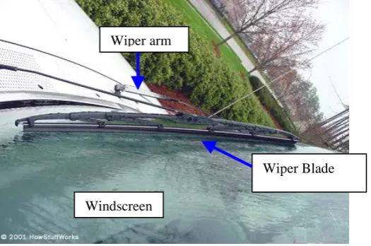
Figure 1.1: Wiper Blade
1.3 Objective
The objective of this project is to design and analysis new automotive wiper retractor system, which can increase the life safe of the blade from excessive exposure to heat and moist.
1.4 Scope
1. Design the retractor system for the wiper for passenger vehicle.
2. Modeling in CATIA/Solid Work for component involved to create the retractor.
3. Develop an electrical circuit for wiper retractor system to function effectively.
4. Perform an analytical study on critical component using COSMOSWORK. 5. Create a working model to present idea and workability of the system.
6. Recommend correct material to be used for the retractor system actual production.
Wiper arm
Wiper Blade
It is expected that, the product will be able to fulfill the task required. Firstly proper system is developed. Through the developed system and design of the retractor, the driver can now be able to control the wiper retractor from inside the vehicle. The time to come out of the vehicle to lift the wiper can be avoided. The rubber of the wiper is also preserved for longer time. The wiping during rainy and dusty day also becomes much more efficient.
1.6 Content Overview
4
CHAPTER II
LITERATURE REVIEW
A literature search was performed to study, design and analysis the retractor system for the car wiper. It also includes the investigation of what others have done in this area. This study included the areas of electric and electronic as a guide to design the circuit for the retractor.
2.1 Background of The Project
The importance of wiper blades is not given much attention not only nowadays, but also during the first introduction of the blades. These results in many blades which are cracked split, torn, brittle, worn or otherwise in obvious need of replacement. Some may seem to be in good condition, but in fact does not perform to a good quality wiping when put to test.
W.1999). But eventually all blade materials fall victim to environmental factors. Exposure to sunlight and ozone causes the rubber to age, even if the wipers are not used much.
Blades which have lost its flip over flexibility cannot perform the wiping task cleanly. They may develop a permanent set called "parked rubber” or curvature which prevents full contact with the windscreen (everblades.com). This tends to be more of a problem on vehicles that is parked outside in the hot sun all day. The sun bakes and hardens the rubber. Then when the wipers are needed, they streak and chatter because they have taken a set and would not follow the curvature of the windshield. It can be annoying and dangerous.
Cold weather also can affect blade life. Freezing temperatures makes rubber hard and brittle, which increases the tendency to crack and split. The wiper arm can become clogged with ice and snow, preventing the holder from distributing spring tension evenly over the blade. The blade "freezes up" and leaves streaks as it skips across the glass. (A. Koenen, 2007).
Heavy use can be hard on wiper blades too. This is because dust, abrasives, road grime and even bug juice wear away the edge that the blades need to wipe cleanly. As the blade loses its edge, water gets under the blade and remains on the glass. It results in reduced visibility and poor wiping action. Blade that is chattering, streaking or not performing well should be replaced. Blade that is cracked, torn, nicked or damaged should be replaced as well.
This project is to create a wiper retractor that operates automatically to lift and lower the wiper blade from touching the glass. This is intending to increase the life cycle of the wiper blade rubber because can avoid contact of blade with glass at hot and cold weather. So the temperature effect can be reduced.
6 direct current from the battery is used to give the power supply to the retractor. In relation to develop this system, the knowledge and understanding of the working principle of the wiper system, electrical circuit and fatigue analysis must be obtained.
2.2 Understanding the Wiper System
2.2.1 Functional Requirements
The requirement of the wiper system is simple. The windscreen must be clean enough to provide suitable visibility at all times. To do this, the wiper system must meet the following requirements.
• Efficient removal of water and snow • Efficient removal of dirt.
• Operate at temperature from -30 to 80°C
• Service life in the region of 1500 000 wipe cycles • Resistant to corrosion from acid, alkali and ozone
Figure 2.1: Windshield Washer Technique (Source: howstuffworks.com)
2.2.2 Wiper blades
The wiper blades are made of a rubber compound and are held on to the windshield wiper glass by a spring in the wiper arm. The aerodynamic properties of the wiper blades have become increasingly important due to the design of the vehicle as different air currents flow on and around the screen area. The strip on top of the rubber element is often perforated to reduce air drag. A good quality blade will have a contact width of about 0.1mm. The lip wipes the surface of the screen at an angle of about 45°. The pressure of the blade on the screen is also important as the coefficient of friction between the rubber and glass can vary from 0.8 to 2.5 when dry and 0.1 to 0.6 when wet. Temperature and velocity will also affect these figures. (Total Automotive Technology, Anthony E. Schwaller).