Design and Performance of Ropes for Climbing and Sailing A.J. McLaren
Department of Mechanical Engineering, University of Strathclyde, 75 Montrose Street, Glasgow G1 1XJ, Scotland, UK
Abstract
Ropes are an important part of the equipment used by climbers, mountaineers and sailors. On first inspection, most modern polymer ropes appear similar, and it might be assumed that their designs,
construction and properties are governed by the same requirements. In reality, the properties required of climbing ropes are dominated by the requirement that they effectively absorb and
dissipate the energy of the falling climber, in a manner that does not transmit more than a critical amount of force to his body. This requirement is met by the use of ropes with relatively low longitudinal stiffness. By contrast, most sailing ropes require high stiffness values to maximise their
effectiveness, and enable sailors to control sails and equipment precisely. These conflicting requirements lead to the use of different classes of materials, and different construction methods for
the two sports. This paper reviews in detail the use of ropes, the properties required, manufacturing techniques and materials utilised, and the effect of service conditions on the performance of ropes. A survey of research that has been carried out in the field reveals what progress has been made in
the development of these essential components, and identifies where further work may yield benefits in the future.
List of Notation Used
g Acceleration due to gravity, ms-2
H Twice the vertical distance between the climber and the last running belay, m
k Rope elasticity, N
L Total length of rope used, m
m Total mass of lead climber and equipment carried, kg
P Instantaneous load transferred to the rope, N
Pmax Maximum load transferred to the rope, N
Tg Glass transition temperature, °C
x Instantaneous elastic extension of the rope, m
1. Ropes for Climbing
1.1 Introduction
Climbing ropes are predominantly used for safety and security. In particular, they must hold the weight of the climber in the event of a fall. The type and magnitude of forces encountered depend
chiefly on the type of climbing being undertaken. For convenience, climbing activities may be split into three categories: top roping, lead climbing and abseiling. Detailed descriptions of climbing and
abseiling techniques are available elsewhere [1, 2], but a brief description is given here to enable the reader to appreciate the context of the ropes’ use.
Top roping is the most common form of climbing carried out at indoor climbing walls, and is also widely practiced on small crags or outcrops where the top of the route may be reached without
A fixed anchor point is set up at the top of the route and the rope is looped through a karabiner attached to this anchor. The two halves of the rope are dropped to the bottom of the climb to form a
simple pulley system. The climber ties one end to his harness, while his partner, known as the belayer, secures the other end to his harness by the use of a friction device. This device allows the
rope to be taken in or paid out under control, but can be quickly locked to form a solid attachment to the rope. The climber ascends the route while the belayer takes in the slack rope until the climber reaches the top. At this point, the climber may untie himself from the rope and walk down to the
bottom of the crag, or may place his weight on the rope and be lowered to the ground, under the control of the belayer, by means of the friction device. This latter practice is the norm for indoor
climbing walls.
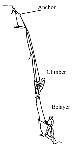
Lead climbing is used in situations where the top of the route is inaccessible by any means other
than climbing. Figure 2 shows the typical arrangements for lead climbing. This is typical of climbing carried out on mountains or large crags. In this case, the lead climber ties one end of the
rope to his harness, while the belayer passes the rope through the friction device a few metres from the same end. The lead climber begins to climb, towing the rope behind him, and the belayer pays out slack at an appropriate rate. Periodically, the leader will stop and attach the rope to “running
belays”. These are anchor points on the route, which may consist of pieces of equipment such as wedges or camming devices that the lead climber carries with him on the climb. These are placed
temporarily in cracks in the rock, and are designed to take the weight of the climber should he fall. Alternatively, pre-placed expansion ring bolts may be used. In either case, the rope is clipped to the anchor points by the use of a karabiner, which allows the rope to continue to run through the
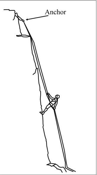
Once the leader has reached the top of the climb, or runs out of rope, he will stop climbing and attach himself securely to the rock. He then becomes the belayer, while his partner climbs the route
with the security of a top rope. As he climbs, the partner will remove all the running belays as he passes them, thus allowing their re-use at a later stage of the climb.
On mountains and large crags, where the route is longer than a typical 50m rope, lead climbing is carried out in a series of pitches. Once the second climber joins the leader at the belay, they
organise their equipment and begin the process again. In this way, a large route or mountain may be broken into a series of short pitches, and the climbers progress up the route as a self contained unit.
Abseiling (also known as rappelling) is used to descend steep ground by sliding down the rope in a controlled manner. Climbers generally use this technique when descending or retreating from
mountain routes. Friction devices, similar to those used for belaying, are utilised to control the rate of descent. Figure 3 shows the typical arrangements for abseiling. The usual technique is to double
the rope to allow its retrieval from below once the bottom of the abseil pitch is reached. On mountain routes, this may involve the sacrifice of a piece of equipment, which is left behind at the anchor point.
Modern mountaineering ropes are classified into four classes, which are approved by the UIAA
(Union International des Associations d’Alpinisme). Each rope must be clearly marked with a standard label indicating which class it belongs to.
Half ropes are used in pairs. The leader will clip one of the ropes into each running belay. This
gives extra flexibility for belay placements. For instance, if climbing a broad crack with running belay placements on both sides, the leader will clip one rope to runners on the left, the other to
runners of the right. In this way, each rope will run approximately vertically, which will greatly reduce frictional drag. Half ropes have the additional advantage that they can be joined together for abseiling, thus doubling the distance that can be descended in one pitch. Half ropes are generally
thinner than single ropes, typically 8 or 9mm diameter.
Twin ropes are also used in pairs, with both ropes being clipped into each running belay. Their use is very rare in the UK, but they are used in the Alps. Their diameter is generally similar to, or smaller than half ropes, making them very light weight.
The fourth category of rope is the mountain walking or tour rope. This is used to provide security
on mountain walks, for glacier crossing or ski mountaineering. It is normally an 8mm diameter dynamic rope, but is not suitable for rock climbing.
The properties that are required for climbing ropes depend chiefly on their task of arresting the fall of a climber in a controlled manner. In top roping, the maximum fall that is possible is less than one
metre (providing the belayer is paying attention). However, depending on the vertical spacing of available running belays, a leader may fall a much greater distance. Indeed, the fall distance will be approximately twice the distance from the leader to his last running belay anchor. In general, the
availability of anchor points, and/or the ability of the leader to hang on while placing them, decreases as the difficulty of the route increases. Indeed, falls of several metres are not uncommon.
without transmitting large forces to his body through his harness. For this reason, relatively elastic ropes, which stretch appreciably when loaded, are desirable in climbing.
1.2 Fall forces
The design of a suitable rope for arresting the fall of a lead climber requires an appreciation of the forces that are likely to be generated. Smith [3] reviews and extends the analysis by Wexler [4] of
the forces generated in a lead climber fall. The geometry of this ideal fall is shown in Figure 4. The maximum force, Pmax (N) generated in the fall of a climber of mass m, depends on the geometry of
the fall and the properties of the rope involved. This is given by the following equation.
max
2
=
1+ 1+
k
•
H
P
mg
mg
L
⎡
⎤
⎢
⎣
⎦
⎥
(1)Where H (m) is twice the distance from the climber to the running belay, L (m) is the total length of rope used, g is the acceleration due to gravity (9.81ms-2), and k (N) is a measure of the rope’s elasticity, defined by:
x
P
k
L
⎡ ⎤
= ⎢ ⎥
⎣ ⎦
(2)Where x (m) is the elastic extension of a rope of initial length L (m) under an instantaneous load P
It is clear that for a climber (and associated equipment) of a given mass, the maximum fall force may be minimised by employing a rope with a low value of k. This allows relatively large
extensions, but generates relatively small forces. An extreme example of this effect is the use of thick, highly extensible ropes for bungee jumping.
The geometry of the fall may be characterised by the ratio H/L. This is known as the “fall factor”, and is essentially a measure of the ratio of potential energy put into the rope by the falling mass, to
the amount of elastic material available to absorb this energy. Theoretically, values of fall factor are possible between 0 and 2, with a fall factor of 2 corresponding to a leader fall on steep ground with
no running belays. (The leader will fall past the belayer, the fall distance being twice the length of the rope between them at the moment the fall begins.)
In practice, the geometry of leader falls is seldom this simple. Climbing routes tend not to be straight, so the path of the rope becomes more convoluted, and where running belays are scarce, the
rope may deviate significantly from the ideal straight line. Pavier [5,6] has developed theoretical models to predict the tension generated in ropes under a variety of fall geometries. His analysis takes into account the slip of the rope through the belay friction device, friction at running belays
themselves, and a visco-elastic model for the rope.
1.3 Standards and Testing
Experimentation has revealed that the generally accepted maximum load that the human body can
in so doing transmits a fatal force to the climber. The international standard test for climbing ropes is based on a standard dynamic drop test [7] of relatively high fall factor.
The test uses a machine, known in the industry as a “DODERO”, which performs the standardised
drop test. This simulates a leader fall for a climber with a fall factor of 1.78. This corresponds to a vertical fall distance of 5m with a total length of rope of 2.8m. The rope passes through a standard ring that simulates a running belay, and it is generally the friction generated between this point and
the surface of the rope that initiates failure.
For a single rope, the maximum transmitted force for a mass of 80kg is 12kN. For double ropes and twin ropes, a single strand is tested with a mass of 55kg, and the maximum permitted load is 8kN. Each rope must also withstand 5 consecutive standard falls without failure. It is generally found that
the rope stiffens after the first drop test, leading to higher loads on subsequent drops.
In addition to the number of falls and maximum load criteria, ropes must conform to minimum standards concerning knotability, extension under load, extension during standard falls, as well as sheath slippage: the amount of relative longitudinal movement between the sheath and the inner
core. A concise account of the standards is contained in the short review by Bennett [8].
The implication of this test is that the most important performance criterion for the rope is its energy absorption characteristics. By nature, climbing ropes will be designed to stretch significantly under load.
descent. These are undesirable for two main reasons: the descending climber may be put off balance or be disorientated if significant oscillation occurs; the rope may be loaded over sharp edges and the
oscillation can contribute to a sawing action which is detrimental. For this reason, static ropes, with limited extension are used by people who participate in abseiling as an exercise in its own right, e.g.
outdoor activity centres. However, it is not practical for mountaineers to carry additional ropes for this sole purpose, so they would normally abseil on their dynamic climbing ropes.
1.4 Desired properties for rope
The desired properties for a dynamic climbing rope are therefore as follows:
• High strength; ability to support static force, and repeated dynamic loading.
• Known elastic properties which allow the rope to control the force transmitted to the climber
and equipment during a fall.
• Light weight.
• Durability; resistance to abrasion, ultra violet light and repeated thermal cycling.
• Water resistance; stability of mechanical properties in the presence of water.
• Handling characteristics; feel, knotability, stiffness.
The first climbing ropes were made of natural fibres such as hemp or manila. They evolved directly from ropes used for general and marine applications, and were formed of twisted yarns. This type of
construction is known as “hawser laid”, and generally consists of three parallel helical strands. The twist of the individual strands is in the opposite direction to the helix, and this twist locks and
While these ropes were adequate for simple security and top roping, they were notoriously ineffective at arresting leader falls. The old climbing adage, “the leader must not fall,” comes from
an understanding of the likely consequences of a leader fall onto a natural fibre rope. The relatively high stiffness of hemp and manila lead to the generation of large dynamic forces during falls. Smith
[3] estimates that fall factors of 0.5 for hemp and 0.75 for manila would be sufficient to cause failure.
The first advance towards modern ropes came during the Second World War, with the introduction of nylon fibres by DuPont. Initially, hawser laid ropes were constructed, substituting nylon fibres
for the natural products. The results were ropes that could take a fall factor of approximately 1.0 before breaking. These ropes, while superior to those made from natural fibres, were notoriously stiff if allowed to become wet. This made the tying (and untying) of knots difficult, and greatly
reduced their handling characteristics.
In 1951, the first “kernmantel” ropes were produced by Edelrid. The structure of kernmantel ropes is shown in Figure 6. The core (kern) consists of parallel bundles of twisted strands, each one of which resembles a small hawser laid rope. The individual strands are often twisted in opposing
directions (some clockwise and some counter clockwise). This helps to minimise excessive spinning or twist while abseiling or lowering. The core is generally responsible for the mechanical
properties of the rope with regard to tensile strength and dynamic behaviour, and is covered with a braided sheath (mantel). The purpose of the sheath is to contain and protect the core. However, the construction conditions of the sheath have significant effects on the properties of the rope,
1.5 Modelling of Ropes
The literature on the modelling of textile ropes is limited. Much of the research that has been carried out on rope structures is concerned with wire ropes, more commonly used in large engineering
structures and offshore applications. The standard text in this area is the book by Costello [11]. Several authors have attempted to model textile fibre ropes. A good review of work in this area was recently published by Pan and Brookstein [12].
Manes [13] has applied wire rope modelling techniques to kernmantel climbing ropes, including predictions of stress distributions during the DODERO dynamic fall test, where the rope is bent around a bar of 10mm radius. He also attempts to model the behaviour over a 0.75mm sharp edge, but his results are inconclusive. Contri and Secchi [14] have attempted to model the cutting of a
loaded rope by a sharp edge. Their approach considers the rope as a hierarchical structure of fibres/filaments, yarns/plies, strands and overall rope, each component of which may transfer load
to its neighbours by friction. In this sense, their approach is similar to that of Leech [15], who, with co-workers, has also published the results of modelling work on the effects of cyclic loading on rope properties [16].
The mechanisms of rope failure have been studied by Phoenix [17], who has analysed load transfer
between neighbouring strands in the rope. Failure of an individual strand leads to partial or total load transfer to adjacent strands by friction. The mechanical behaviour of rope structures is complex and highly non-linear, which poses considerable problems for modelling of failure mechanisms,
1.6 Environmental effects and service conditions
Rope Age
Blackford [18] reviews several instances of rope failure that have occurred since 1985. Her conclusion is that, with the exception of two incidents involving chemical contamination (battery acid), the remainder of rope failures are associated with cutting or abrasion over a sharp edge. An
extensive review by Schubert [19] of rope failures amongst German and Austrian climbers since 1968 reveals the same pattern. Schubert tested a range of ropes of different ages (some as old as 30
years) using the DODERO standard drop test. He reports that none of the ropes tested failed after one test, and since real falls are never likely to be as severe as the drop test, ropes are very unlikely to fail by breaking at a knot, running belay, or at a belay friction device. The only likely instance
where failure might be expected is over a sharp edge [20].
Nevertheless, ropes may clearly be seen to deteriorate with age. Schubert [21] uses the concept of “metres climbed” to characterise the age of a rope. He has studied the rate of loss of energy absorption capacity with age (metres climbed). Some 50% or the energy absorption ability appears
to be lost in the first 2,000 to 4,000m climbed, with reductions as large as 90% after 20,000m. He notes that the rate of ageing will depend on the severity of use.
Water absorption
necessary to consider the effect of water absorption of the effectiveness of the rope as a fall arrest system.
Cotugno et al [22] review the processes involved in the absorption of water by polymeric yarns. The
plasticization effect of water causes reductions in elastic modulus and yield strength. This occurs by changing the mechanisms of yield and deformation, as well as the cutting of polymer chains by hydrolysis. The authors show that the equilibrium water content of a specific polymer is not
sensitive to temperature, whereas the rate of absorption is controlled by diffusion, and is therefore strongly temperature dependent. Different polymers absorb water to different extents. Polyamides
tend to be “hydrophilic”, i.e. the molecules possess specific sites that attract water molecules. The authors report research carried out by Mensitieri et al [23] and Del Nobile et al [24] comparing water absorption in nylon-6 with a more hydrophobic ethylene-propylene co-polymer. The nylon-6
absorbs 10 times as much water as the co-polymer. This causes changes in mechanical properties equivalent to a reduction in the polymer’s glass transition temperature. The degree to which water
can affect mechanical properties depends on the exact nature of the interaction between the polymer and water molecules. The authors report that the technique of FTIR (Fourier Transform Infra Red) spectroscopy may be utilised to identify these specific interactions [25]. Absorption of water
involving the establishment of strong hydrogen bonds between the water molecules and the polymer, leads to high levels of plasticization by the breaking of secondary bonds between adjacent
polymer molecules. Polymer systems that show weak interaction with water molecules are plasticized relatively little by the action of water.
Signoretti [26, 27] studied the effect of wetting of ropes on the results of DODERO drop testing. He reports that the number of falls withstood is reduced to 30% of the value for the original dry rope.
effect, equivalent to a short rain shower. However, it should be noted that every rope in his study withstood at least one standard fall, irrespective of condition. This suggests that while water
absorption has a significant effect, it does not render the rope ineffective. He also tested ropes treated by the manufacturers with waterproof coatings. He observes that these coatings stop water
sticking to the threads but do not stop water absorption in the molecules of the yarn. He states that the absorption of water has an equivalent effect to a increase in temperature [28].
Signoretti also reports that the first fall on the DODERO for the wet ropes showed an increase in force of 5 to 10%. He proposes that this may be due to increased friction between fibres induced by
wetting, or possible swelling due to water absorption.
Recent work by Smith [29] has confirmed that water absorption has the most significant effect on
static strength and stiffness. He also reports that water uptake appears to be more significant in fresh water than in simulated sea water conditions. In both conditions, drying of the rope causes partial,
but not complete recovery of the properties with respect to those of the new rope. This is in agreement with the findings of Signoretti.
UV light
Signoretti [30]: has also examined the effect of UV exposure on the number of DODERO falls withstood. He exposed samples of rope to sunlight at mountain huts in the Dolomites, and tested both the static strength of filaments and dynamic fall holding ability. He reports a 35% decrease in
reference to the intensity of sunlight at different altitudes. The decrease in dynamic performance of the ropes is greater than the difference in static strength of the filaments.
Photo-oxidation changes the chemical structure of the nylon molecules. This occurs by
de-polymerisation, leading to decreases in both energy absorption and elasticity. The most common methods for reducing the rate of these processes involve the photo-chemical stabilisation of the nylon, either by the inclusion of anti-oxidant products, or the incorporation of UV protection agents,
similar to those used as filters in sun screens.
UV light tends to have an effect on the appearance of the rope. The fashion these days is for brightly coloured and contrasting strands in the braided sheath. Signoretti observes that decolourisation of the sheath by UV exposure may be loosely correlated with loss of performance.
Freezing
Climbing in winter in the UK, and at all times in the higher mountain ranges, exposes ropes to low temperatures, in all likelihood accompanied by cycles of wetting and drying. Odriozola [31,32]
observed a 30% reduction in static resistance for wetted and frozen ropes compared to the initial performance of the dry rope. Signoretti [27] shows that the number of falls withstood is reduced by
Heat Glazing
McCartney et al [34]: have studied the effects of heating due to rapid abseiling or sack hauling (on big wall rotes, rucksacks are often hauled up behind the climbers using pulley systems). These
activities cause localised damage to the sheath by frictional melting of a thin layer. While the depth of melting is generally small, it implies significant local temperature increases in the rope surface.
The authors report that the UTS of the core was not affected by external glazing, but that the extensibility of the core strands increases by 40% adjacent to damaged side, and by 20% on the side
opposite the glazing damage. They propose that the temperature has locally been above the glass transition temperature, Tg, which alters the molecular arrangement in the yarns, increasing
amorphous proportion.
Particle entrainment
Pavier [35] observed a decrease in the number of falls sustained by ropes treated externally with grit particles. Smith [29] studied the effect of sand absorption on the static strength of ropes. Ropes
were conditioned by rubbing sand into the surface of the sheath, and tested in a tensile testing machine. He reports a 25% decrease in static strength as compared with the new rope. In addition,
the observed mechanism of failure was significantly different from any other rope tested. The usual failure mode involves catastrophic breakage of the whole rope at the failure load, without prior warning. For the sand treated samples, the sheath failed first, at relatively low loads, followed by
1.7 Summary
The property requirements for dynamic climbing ropes are dominated by the need for effective energy absorption in a leader fall. This demands that ropes not only be strong, but that they retain
well controlled load elongation behaviour throughout their life. The materials and construction of climbing ropes have evolved from traditional natural fibres, with a “hawser laid” structure, to the modern kernmantel construction, consisting of parallel twisted yarns surrounded by a braided
sheath. The majority of today’s climbing ropes are manufactured from semi crystalline nylon-6, the properties of which are controlled by the relative fractions of axially aligned crystalline and
amorphous phases.
While environmental conditions and use do affect the properties of ropes; notably by water
absorption, UV light, freezing, heat glazing and particle entrainment, none of these factors are considered to render ropes unsafe. The observation is that ropes under all of these conditions retain
sufficient strength and elasticity to sustain at least one standard leader fall, and the conclusion is that modern dynamic ropes do not break in service. The exception to this pattern involves dynamic loading over sharp edges, which is said to have accounted for all but two of the reported rope
failures in the past 35 years, i.e. since the modern climbing rope was developed.
2. Ropes for Sailing
2.1 Introduction
Standing rigging consists of structural components that support the mast and spars, together with equipment such as guard rails which are present for reasons of safety. By its very nature, standing
rigging is semi permanent, and tends to be adjusted infrequently, usually when setting up the mast at the start of the day for dinghies, or the start of the season for yachts.
The running rigging is used to hoist and/or control the sails. Halyards are used to hoist the sails into position; sheets are attached to the sails and are used primarily to control their angle to the boat’s
centreline, and therefore the wind. The running rigging will also generally include ropes that are used to control the position of moveable components of the boat, which are used for fine adjustment
of the sails. The ropes in the running rigging will generally pass through pulleys and blocks that are used to control the line of action of the ropes, and increase mechanical advantage. On yachts, the sheets and halyards are usually tensioned using geared capstan winches, which multiply the forces
exerted by the human body to the magnitudes required.
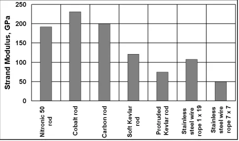
Standing rigging components are essentially structural. Traditionally they were made of rope, but the most usual material in use today is twisted stainless steel wire rope. For high performance applications, solid rod rigging, often made from Nitronic 501, nitrogen alloyed stainless steel is utilised. The strand moduli of a variety of standing rigging materials are shown in Figure 7, re-plotted from the work of Gilliam [36]. Strand modulus is used in preference to Young’s modulus;
load extension data from an actual strand is used together with the nominal diameter of the strand to calculate the effective modulus of the cable or rod.
handling properties, and low weight. However, in one important respect the property requirements are quite different. Sailing ropes must have high levels of stiffness. The requirement for energy
absorption in shock loading conditions is removed. Indeed, the very elasticity which facilitates this ability in climbing ropes would be a serious disadvantage for running or standing rigging
components in sailing craft.
Elastic stretch in ropes used to control sails or other components would limit the precision with
which adjustments could be made. For instance, the tension in a halyard has a fundamental effect on the three dimensional shape of the sail, and therefore its aerodynamic behaviour. It is desirable to be
able to make fine adjustments to halyard tension while sailing, since the sail shape requirements vary considerably with wind strength, point of sailing (the angle between the wind and the boat’s heading), wave conditions and tactical considerations relating to the position relative to competing
boats.
Fine adjustment is facilitated by the use of halyards that possess high longitudinal stiffness. This is particularly important since halyard adjustments are usually made by the use of a winch in the boat’s cockpit. The total length of halyard between the head (top corner) of the sail and the winch is
approximately equal to the height of the mast plus the distance form mast to cockpit. For a typical 10m racing yacht, this distance might be approximately 15m. The full range of halyard tension is
likely to be accomplished by adjustments of 15cm at the winch, i.e. approximately 1% of the halyard length. Fine adjustment may require movements of less than 1cm, less than 0.07% of the halyard length. Materials of high stiffness are desirable because they allow ropes of relatively small
diameter to be used, while still supporting the considerable loads generated. Small diameter ropes not only save weight, important in its own right for racing sailors, but also reduce the cross section
sails, any items aloft that do not contribute to this drive, can only increase drag and/or healing force, with the associated reduction in efficiency.
While halyards are perhaps the most critical ropes from the point of view of fine adjustment, the
same requirements certainly apply to most other components of the running rigging. Sheets that control sails may be highly loaded, particularly when sailing upwind, when the sails are pulled tightest. Winches on racing yachts are characterised by their power ratio which is defined as the
ratio of sheet load produced, divided by the force applied to the handle. For a typical 10m racing yacht, winches with a power factor of approximately 40 might be expected. Therefore, a relatively
light crew member, say 80kg in weight, exerting one quarter of their body weight as a force on the winch handle, might be expected to generate a sheet load of 8kN. It is interesting to note that this is equal to the maximum load permitted for half ropes and twin ropes in the dynamic drop test for
climbing ropes. In reality, loads far in excess of this value might be expected in sailing ropes.
2.2 Materials and Construction
An excellent review of ropes for sailing has recently been published by Pawson [37]. He reviews
the history of rope materials from the early natural fibres such as hemp, manila and sisal, through the discovery of nylon in the 1930’s and the later development of Polyethylene (PE), Polyester
(PES) and Polypropylene (PP). Of the man made fibres, nylon is not particularly suitable due to its high stretch (the very property that makes it ideal for climbing ropes). The high degree of stretch makes it unsuitable for halyards and sheets, for the reasons explained above. In addition, should a
The majority of sailors use polyester ropes for running rigging. The ropes are heat treated and pre-stretched in the manufacturing process to give high longitudinal stiffness. The construction
generally consists of a “braid on braid” structure; formed from braiding an eight or 16 strand hollow plait over a core of another hollow braid. These ropes give excellent friction and handling
properties, in addition to good stiffness.
Polypropylene is cheaper than polyester, but its wear and UV resistance properties are inferior. It
has relatively low density, which makes it float, which can be an advantage for some applications, e.g. floating heaving line for man overboard situations.
2.3 Exotic Materials
At the high performance end of the sport, e.g. the America’s Cup, considerable development has been carried out into the use of exotic specialist materials to reduce weight and increase
performance. The first example in use was the aramid fibre known as Kevlar2. (Alternative trade names include Twaron3 and Technora4) It shows very low stretch, is very strong and light weight. However, its properties in bending are somewhat poorer, particularly over pulleys and sheaves, and
this has led to the development of blocks with larger sheaves to alleviate this problem. All these fibres must be protected from UV degradation and chafe, and for this reason, the core of the rope is
constructed from the specialist fibre, while the braided sheath is usually made from polyester.
Another fibre, now in relatively common use, is HMPE, high modulus polyethylene, sold under the
trade names Spectra5 and Dyneema6. This light, strong fibre has also found uses in climbing. It is
2
Kevlar is a registered trademark of E.I. DuPont de Nemours..
3
Twaron is a registered trademark of Teijin Twaron USA, Inc
4
used to make tape slings and static cord for use in running belays. The dynamic properties of the rope absorb the energy of the fall, but the protective gear placed in the rock is designed as a light
weight, strong, stiff but flexible structure. Here, the weight savings that are possible for a climber carrying a large assortment of protection equipment have led to the adoption of exotic materials.
Most recently, the liquid crystal polyester (LCP) sold as Vectran7, and PBO (p-phenylene-2, 6-benzobisoxazole), sold as Zylon8 have been used by America’s Cup teams, and are starting to make their way into the regular racing market.
None of these most recently developed fibres are cheap, but as with many sports, competitors will readily spend money on materials and equipment that give a perceived advantage, however small this may be in reality. Certainly, there would seem to be more scope for the use of novel and exotic
materials for sailing ropes than for climbing. The cost of ropes and cordage as a fraction of a racing boat’s budget is relatively small, whereas for the average climber, their rope or ropes constitute a
major fraction of the total cost of the equipment they own.
2.4 Knots and Splices
Both sailors and climbers need to make loops in the end of their ropes for various purposes.
Climbers traditionally tied the rope round their waist with a bowline knot, but since the development of good quality sit harnesses, the usual method is to tie the end of the rope to the harness by use of a double figure of eight knot. The current advice on the use of knots by climbers
Sailors also traditionally use knots to make loops in the end of a rope. In particular, the bowline is generally used to attach the sheets to the clew (bottom, rear corner) of a headsail. This knot is easy
to tie, and can be untied quickly once unloaded. This is better than a permanent attachment since any rope tangles can be quickly sorted out by untying the knots if necessary. Sheets also tend to be
stored below deck when not in use, so need to be attached to the sail on each occasion that the boat is raced.
Recent work [39] utilised static tensile testing to measure the strength of a variety of knots and splices used to make loops in the end of polyester sailing ropes. Four knots were evaluated;
bowline, double bowline, perfection loop and double figure of eight. All knots broke at between 55% and 84% of the rope strength, with the double figure of eight being significantly stronger than the others. This result is likely to be reassuring to climbers who use this knot for tying into their
harness, but for sailors, the knot’s extra strength is outweighed because it is relatively difficult to untie once it has been loaded. The authors also examined the strength of splices used to make loops
in hawser laid as well as braid on braid ropes. Compared to knots, splices provide a significantly stronger loop. However, they can only be used where the loop is required to be semi permanent.
Other workers [40, 41] have addressed the subject of splices and end terminations for both steel and polymer fibre ropes. The non linear nature of these materials and the complexity of their structural
interactions make modelling in this field challenging.
3. Future Developments
properties of the rope are governed by the core material, so traditional braid-on-braid splices are inappropriate for these constructions. Manufactures have designed new splicing techniques in order
to make core to core splices. The practice of stripping off the cover and using the core alone is commonplace, particularly for ropes that form standing rigging components such as backstays, or
spinnaker pole bridles. The tails of sheets and halyards cannot be used without the cover, since this makes for difficult handling using winches and jammers. The solution is the production of tapered sheets and halyards, stripped at the working end, but covered at the tail.
Future developments are likely to involve the inclusion of exotic materials in the structure of the
cover itself. Pawson [37] mentions several examples, mostly from developments for America’s Cup teams: Covers have been used that contain pre-stretched Dyneema, over cores of Vectran, Dyneema or PBO. Covers containing PBO have also been developed to give greater wear resistance. Despite
the fact that these ropes are very expensive, their use actually saved money because the standard polyester covered ropes needed to be replaced after each race. The relatively poor UV resistance of
PBO is not seen as a problem, since the ropes need to be replaced for reasons of wear after two race series, long before the effects of UV become apparent.
Other manufactures have developed covers containing Nomex9 or Aramid fibres. These help prevent melting due to frictional heating on winch drums when sheets are being eased. These ropes
may lead to scoring of carbon fibre winch drums, so rope and winch manufactures are working closely together to solve these problems.
developments have occurred in the materials and construction methods used in sail making. It is common to see the same club and regatta sailors using laminate sails, reinforced with such exotic
materials as Kevlar, carbon fibre and Vectran. This may indicate that more exotic, high performance ropes will start to be used by sailors outside the elite group.
By contrast, the average climber is unlikely to be willing to pay a high premium for a small increase in performance. The general conclusion from the study of climbing accident statistics is that ropes
don’t break, other than when loaded over an edge. Reasonable weight savings have been achieved by the use of smaller diameter ropes, particularly amongst sports climbers. However, larger weight
savings are possible by enhanced design of running belay equipment, and this has seen considerable development in recent years. Improved rope coatings may increase UV resistance and reduce water absorption, which will be of benefit to mountaineers.
4. Conclusions
The apparently similar ropes used by sailors and climbers are in fact very different. The major
design constraint for climbing ropes is the requirement to absorb and dissipate the energy of leader falls, without transmitting large forces to the climber. This requires a rope of moderate to low
longitudinal stiffness, but high strength. This is achieved by the use of polyamide nylon-6, formed into a kernmantel structure of parallel twisted yarns surrounded by a braided protective sheath.
Environmental damage due to ageing, water absorption, UV light degradation, freezing, heat glazing and particle entrainment has a significant effect on the properties of the rope, and decreases
properties of the rope to levels that would cause failure in use. The most significant threat to safety is the cutting of a rope that is loaded over a sharp edge.
The relationship between structure and properties is complex, and while the problem of describing
it has responded to various modelling techniques, there is still scope for further work in this area.
Sailing ropes, especially for boats involved in racing, require a different portfolio of properties. In
particular, high longitudinal stiffness to weight ratios are dominant constraints. Precise control of sails and other equipment by rope actuators leads to the need for low stretch materials. Traditional
natural fibres have been replaced by man made polymers, notably polyester, formed into ropes with a braid on braid structure.
In high performance applications, more exotic core materials, usually covered with a braided polyester sheath are used. These materials give enhanced stiffness to weight ratios, but incur a
considerable monetary cost. Although their use was initially confined to the top echelons of competition, they are becoming more widespread at all levels of the sport.
4. References
1 Langmuir, E., Mountaincraft and Leadership, MLTB, Scottish Sports Council, 3rd Edn, ISBN 1-85060-295-6
2 Fyffe, A. and Peter, I. The Handbook of Climbing, Pelman Books, 1997, ISBN 0-72072-054-0
3 Smith, R.A., The Development of Equipment to Reduce Risk in Rock Climbing, Sports Engineering, 1998, 1, 27-39.
4 Wexler, A. The Theory of Belaying, American Alpine Club Journal, 1950, 7, 379-405. (Published in the UK as a separate Special Supplement of Mountain Craft.)
5 Pavier, M.J., Derivation of a Rope Behaviour Model for the Analysis of Forces Developed during a Rock Climbing Leader Fall, in Proceedings of the 1st International Conference on the Engineering of Sport, ed. S.J. Haake, A.A. 1996, 271-279, (Balkema, Rotterdam).
6 Pavier, M.J, Experimental and Theoretical Simulations of Climbing Falls, Sports Engineering, 1998, 1, 79-91.
7 BS EN 897: Mountaineering equipment, Dynamic mountaineering ropes, Safety requirements and test methods, October 1996.
8 Bennett, F. Learning the Ropes, Summit, 2000, 20, 28-29.
9 Karrer, R. The Perfect Rope- Production and Use, in Nylon and Ropes for Mountaineering and Caving, 8-9 March 2002, Turin, (Italian Alpine Club Technical Committee). Online at http://www.caimateriali.org/Eventi/torino.html
10 Beal, M., Influence of Parameters in the Rope Construction, as reference [9].
11 Costello, G.A., Theory of Wire Rope, 2nd Ed., Springer Verlag, NY, 1997, ISBN 0-387-98202-7.
13 Manes, A., Analysis of a Textile Rope with Analytical Models, as reference [9]. 14 Contri, L. and Secchi, S., Snapping of Ropes under Stress, as reference [9].
15 Leech, C.M., The Modelling of Friction in Polymer Fibre Ropes, International Journal of Mechanical Sciences, 2002, 44, 621-643.
16 Leech, C.M., Banfield, S.J. and Overington, M.S., The Prediction of Cyclic Load Behaviour and Modulus Modulation for Polyester and other Large Synthetic Fibre Ropes, in Proceedings of Oceans 2003, 1348-1352, (MTS and IEEE).
17 Phoenix, S.L., Statistical Theory for the Strength of Twisted Fibre Bundles with Applications to Yarns and Cables, Textile Research Journal, 1979, 49, 407-423.
18 Blackford, J.R., Materials in Mountaineering, in Materials in Sports Equipment, ed. M. Jenkins, 2003, pp279-325 (Woodhead Publishing), ISBN 1-85573-599-7.
19 Schubert, P., A Number of Rope Failures amongst German and Austrian Mountaineers and Climbers since 1968, as reference [9].
20 Bailie, M., Ropes Don’t Break, Summit, 2000, 17, 17.
21 Schubert, P., About Ageing of Climbing Ropes, Journal of the UIAA, 2000, 3, 12-13. 22 Cotugno, S., Mensitieri, G., Musto, P. and Nicolais, L., Water Sorption and Transport in
Polymers, as reference [9].
23 Mensitieri, G., Del Nobile, M.A., Sommazzi, A. and Nicolais, L., Water transport in a polyketone terpolymer, Journal of Polymer Science B – Polymer Physics, 1995, 33,
1365-1370.
24 Del Nobile, M.A., Mensitieri, G. and Sommazzi, A., Gas and water vapour transport in a polyketone terpolymer, Polymer, 1995, 36, 4943-4950.
Water-26 Signoretti, G., The Influence of Water, Ice and Sunlight on the Dynamic Performance of Mountaineering Ropes, as reference [9].
27 Signoretti, G., Wet and Icy Ropes May Be Dangerous, Journal of the UIAA, 2001, 2, 25-28. 28 Kohan, M.I., (Ed.) Nylon Plastics Handbook, 1995, (Hanser Gardner), ISBN
1-56990-189-9.
29 Smith, M., An Assessment of the Effects of Environmental Conditions on the Performance of Dynamic Climbing Ropes, Final Year Thesis, University of Strathclyde, Glasgow,
(2005).
30 Signoretti, G., Ropes and Sunlight: A matter of colour, La Rivista del CAI, Luglio-Agosto 1999, 76-84.
31 Odriozola, J.A., Estudios previos para ensyos de cuerdas a baja temperature, Revista Peñalara, Abril-Junio 1968, 37-40.
32 Odriozola, J.A., Comportamiente de una cuerda de montaña a baja temperatura, Revista Peñalara, Enero-Marzo 1969, 14-21.
33 Schubert, P., Was halten nasse und vereiste Seile?, Sicherheitskreis im DAV; Tätigkeitsbericht, 1971-73, 197-206.
34 McCartney, A.J., Brook, D. and Taylor, M., The Effect of Heat Glazing on the Strength and Extensibility Properties of Polyamide Climbing Ropes, as reference [9].
35 Pavier, M.J., Failure of Climbing Ropes Resulting from Multiple Leader Falls, in Proceedings of the 2nd International Conference on the Engineering of Sport, ed. S.J. Haake, 1998, 415-422. (Blackwell Science, Oxford.)
36 Gilliam, J., History of Sailing Yacht Masts, Rigging and Sails: 1900 – Present Day, available online at http://boatdesign.net/articles/mast-materials/index.htm.
39 Milne, K.A. and McLaren, A.J., An Assessment of the Strength of Knots and Splices used as Eye Terminations in a Sailing Environment, Submitted to Sports Engineering, 2005.
40 Leech, C.M., Hearle, J.W.S., Overington, M.S. and Banfield, S.J., Modelling Tension and Torque Properties of Fibre Ropes and Splices, in Proceedings of the 3rd International Offshore and Polar Engineering Conference, Singapore, 1993, 370-376.
Figure Captions
Figure 1: Typical arrangement of ropes and anchor for top roping, redrawn from Fyffe and
Peter [2].
Figure 2: Typical arrangement of ropes and anchors for lead climbing; (a) the leader climbing, (b) the partner following with the security of a top rope, redrawn from Fyffe and
Peter [2].
Figure 3: Typical arrangement of ropes and anchor for abseiling, redrawn from Fyffe and Peter
[2].
Figure 4: Geometry of the ideal leader fall, redrawn from Smith [3].
Figure 5: Example of a hawser laid hemp rope from the 1950’s, after Schubert [19].
Figure 6: Construction of kernmantel rope, after Pavier [6].
Figure 7: Elastic properties of various candidate materials for standing rigging, re-plotted from
Belayer
Anchor
[image:32.595.130.462.55.649.2]Climber
Partner
belaying
Running
belay
Leader
climbing
Leader
belaying
Partner
climbing
[image:33.595.46.561.54.642.2](b)
(a)
Figure 2: Typical arrangement of ropes and anchors for lead climbing; (a) the leader climbing, (b) the partner following with the security of a top rope, redrawn from Fyffe and

![Figure 4: Geometry of the ideal leader fall, redrawn from Smith [3].](https://thumb-us.123doks.com/thumbv2/123dok_us/1720080.125404/35.595.69.546.86.395/figure-geometry-ideal-leader-fall-redrawn-smith.webp)
![Figure 5: Example of a hawser laid hemp rope from the 1950’s, after Schubert [19].](https://thumb-us.123doks.com/thumbv2/123dok_us/1720080.125404/36.595.58.450.72.328/figure-example-hawser-laid-hemp-rope-s-schubert.webp)
![Figure 6: Construction of kernmantel rope, after Pavier [6].](https://thumb-us.123doks.com/thumbv2/123dok_us/1720080.125404/37.595.59.455.73.331/figure-construction-kernmantel-rope-after-pavier.webp)