IAC-05- C1.5.05
TRAJECTORY OPTIMIZATION FOR THE
HEVELIUS – LUNAR MICROSATELLITE MISSION
Camilla Colombo, Matteo Ceriotti, Ettore Scarì, Massimiliano Vasile
Politecnico di MilanoVia La Masa, 34, 20156 Milano, Italy [email protected]
ABSTRACT
In this paper trajectory optimisation for the Hevelius mission is presented. The Hevelius – Lunar Microsatellite Mission – is a multilander mission to the dark side of the Moon, supported by a relay microsatellite, orbiting on a Halo orbit around L2. Three landers, with miniaturized payloads, are transported by a carrier from a LEO to the surface of the Moon, where they perform a semi-hard landing with an airbag system. This paper will present the trajectory optimisation process, focusing, in particular, on the approach employed for Δv manoeuvre optimization. An introduction to the existing methods for trajectory optimization will be presented, subsequently it will be described how these methods have been exploited and originally combined in the Hevelius mission analysis and design.
INTRODUCTION
The silvery Moon has gained a renewed interest in recent times, because of both technological and scientific implications. Therefore, after the Apollo era and the more recent Clementine (1994) and Lunar Prospector (1998) missions, a new exploration phase of our natural satellite is envisaged in the near future. On the other hand, the tight constraints on space mission cost and available transportation systems bring about the need for a reduction in the total mass and consequently a minimization of the total required Δv.
In order to answer to the need for cheap scientific missions to the Moon, a multilander mission to her dark side has been recently studied. The mission, called Hevelius, consists
of three landers, with miniaturized payloads, that have to be transported by a carrier from a LEO to the surface of the Moon. In addition, a data relay microsatellite has to support the net-lander on the dark side, orbiting on a Halo orbit around L2.
the equations of motion backward in time to a position near Earth.
A sensible contribute in the study of transfer orbits to libration points through manifold exploitation has been given by Koon, Lo et al. [18][19], Gómez et al. [12][13], Starchville and Melton [23][24]; this strategy has revealed its effectiveness in the design of low-energy transfers to the Moon.
On the other hand, Belbruno et al. [1][2][3][4] proposed new trajectories, exploiting weak stability boundaries (WSB) of the Earth-Sun-Moon system. For this kind of trajectories a long travel time is required but with a significant reduction in propellant mass.
These innovative concepts required the development of specific tools for trajectory design. In particular, the chaotic dynamics governing those trajectories implies the need for methods that assure global convergence at least to a local optimal solution. A possible way to tackle this problem is to generate first guess solutions by using hybrid methods, that combine a global research by Evolutionary Programs and a local optimization by Sequential-Quadratic Programming (SQP).
Genetic algorithms have been used to solve difficult problems with objective functions that do not possess a convenient shape (Davis [7], Goldberg [9], Holland [16], Michalewictz [20]). These algorithms maintain and manipulate a population of solutions and implement a “survival of the fittest” strategy in their search for better solutions, so they can provide for a good initial guess for the optimization. Besides the method used in the SQP optimization is an active set strategy [5] (also known as a projection method), similar to that of Gill et al., described in [10] and [11]. The solution procedure involves two phases. The first phase involves the calculation of a feasible point (if one exists). The second phase involves the generation of an iterative sequence of feasible points that converge to the solution.
In the design of the Hevelius mission, these different methods for trajectory optimization and multi-body dynamics have been investigated in order to design low cost trajectories, to reduce the propellant mass and to fulfil the launcher requirements.
As operative orbit for the data-relay satellite, several Halo orbits around the point L2 of the Earth-Moon system have been investigated by the linearization of the equation of motion around L2, followed by a shooting procedure, or by using a third-order-approximated dynamic model, refined with an SQP procedure. Trade off of the different orbits was based on maintenance cost, amplitude and slew angles.
Earth-Moon transfer exploits stable manifolds leaving Halo orbit, calculated by a backward integration in the RTBP. The total Δv required to insert the spacecraft onto the stable manifold has been initially set as the fitness function of a Genetic Algorithm based process. This process yielded a number of first guess solutions accurately optimised with a SQP solver. In order to phase the departure orbit, the drift effect of J2 and the perturbation effect of the Moon and the Sun have been exploited.
The operative orbit selected for the carrier is a Frozen orbit. The aim of the carrier transfer orbit is to connect a LEO with the Frozen orbit, with the minimum fuel consumption. This transfer exploits the WSB region, in order to obtain a free change of inclination and the required increase of the perigee with a small impulsive manoeuvre. For this problem the software DITAN [26] has been used.
1. THE HEVELIUS MISSION
2. L2-HALO ORBIT DESIGN
2.1. Operative orbit selection
The choice of the final operative orbit for the data relay satellite is driven by the necessity to support a net-lander on the dark side of the Moon; particularly in order to create a constant link between ground stations and the landers, a solution for which both the Earth and the far side of the Moon would always be in the spacecraft field of view has to be investigated. In addition the presence of a LODE (Lagrangian Orbit Determination Experiment) imposes the choice of a periodic orbit around the second collinear libration point of the Earth-Moon system. Hence a restricted three-body problem dynamics has been studied, leading to the design of a Quasi-Halo orbit suitable for the mission.
The non linearity of the problem and consequently the strong dependence on the initial conditions brought the difficult task to find appropriate first guess solutions to be used with a SQP-based shooting procedure.
Three different approaches have been followed changing constraint conditions and objective function. The dynamics is adimensionalised in a rotating x, y, z cartesian reference frame centred in the Earth-Moon centre of mass, with the x-y plane coinciding with the plane of motion of the primaries and the x-axis pointing along the line connecting the two bodies away from the larger primary.
2.2. Shooting
A first guess for the initial state vector has been computed analytically with a linearization of the equation of motion around L2:
2
2 xx
yy
zz
x ny U x
y nx U y
z U z
⎧ = +
⎪ = − +
⎨ ⎪ = ⎩
$$ $
$$ $
$$
where Uxx,Uyy,Uzz are constants. The derived Lissajous orbit is characterized by an in-plane (x-y synodic plane) frequency different from the out-of-plane frequency and corresponds to a non closed solution. Additionally it is valid only in a linear approximation and for restricted amplitudes of motion.
Since a closed solution is needed, a shooting procedure using complete RTBP dynamics is needed. Halo orbits determined in this way are always contained in the x-y plane, i.e. they have no out of plane motion.
Since appropriate amplitudes in the y-z plane are required, a modified shooting has been studied, which assumes a given z initial velocity (out-of-plane), and determines initial x and y velocities and the period of the Halo.
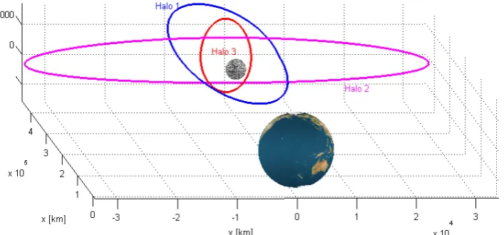
[image:3.595.119.473.87.252.2]in order to avoid eclipses in the communication with the Earth caused by the presence of the Moon. Values greater then 3000 km are sufficient to guarantee the visibility of the entire Earth without any interference from the Moon. The best solution of this type is Halo 1 (Figure 1).
2.3. Third order approximation
In order to overcome the problem of finding a first guess solution, the method developed by Richardson has been followed: details on the problem formulation and equations can be found in [22]. The three dimensional equations of motion are obtained by Lagrangian formulation. The solution is constructed using the method of successive approximations in conjunction with a technique similar to the Lindstedt-Poincarè method. A third order approximation dynamic model is so created through a Legendre polynomial expression of the gravitational field; Halo-type periodic solutions are obtained by assuming the amplitudes are large enough so that the nonlinear contributions to the system produces equal eigenfrequencies. Solutions of this type are analytical, periodic and do not require any correction manoeuvre but only in a third order approximation of the RTBP. The actual mission orbit in the complete model has been constructed numerically as suggested by Richardson [22], solving a Nonlinear Problem (NP) through a Sequential Quadratic Programming, which converges in three or four iterations. The obtained initial state vector is then refined with an SQP procedure
exploiting the symmetry of motion about the x-z plane: the starting solution in fact presents velocities in the x and z directions null when the s/c lies in the x-z plane on the positive z side. A similar condition is imposed after a semi-period in the opposite side of the z axis. This procedure led to solutions like Halo 2 in Figure 1.
2.4. Pointing requirements
In order to design Halo orbits fulfilling the desired pointing requirements the same procedure described in 2.3 has been followed, with the addition of the constraints on the slew manoeuvre angles requiring to point the centre of the Moon (see below) enforced in the SQP optimisation. Halo 3 in Figure 1 represents the best solution of this kind.
The choice of the best target orbit for the mission is accomplished in collaboration with the Telecom and ADCS subsystems. The best compromise between manoeuvres cost, communication and pointing requirements is investigated on the basis of the following parameters:
• Manoeuvres required to maintain a periodic motion;
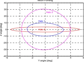
• Spherical angular coordinates of the Moon and Earth versors expressed in a spacecraft reference system. These angles correspond to the slew manoeuvre angles required to point the planets (Z and Y) as shown in Figure 3;
• Angle of the view cone including both the primaries ( );
-3 -2 -1 0 1 2 3 x 10⁴
-4000 -3000 -2000 -1000 0 1000 2000 3000
Y [Km]
Z
[K
m
]
4.32 4.34 4.36 4.38 4.4 4.42 4.44 4.46 4.48 4.5 4.52 x 10⁵
-3 -2 -1 0 1 2 3 x 10⁴
X [Km]
Y [K
m
]
4.32 4.34 4.36 4.38 4.4 4.42 4.44 4.46 4.48 4.5 4.52 x 10⁵
-4000 -3000 -2000 -1000 0 1000 2000 3000
X [Km]
Z
[K
m
[image:4.595.93.498.107.235.2]]
• Coverage area of each one of the two primaries.
[image:5.595.63.286.171.325.2]Table 1 shows the main parameters mentioned above for the three kinds of Halo orbits.
Table 1: Halo trade parameters
Orbit Halo 1 Halo 2 Halo 3
v [m/s] 16 0.03 4.56
Period [d] 15.4 14.8 14.6
Moon max
Y/Z [°] 5.5/3.8 3.9/30.6 3/10 Earth max
Y/Z [°] 0.78/0.5 0.46/4.4 0.39/1.4 Moon [°] 83 57.8 78.4
Earth [°] 88.4 84.8 87.7
Max [°] 7.1 28.7 11
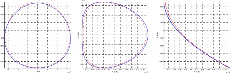
The selected orbit is Halo 2 whose main dimension are listed in Table 2, and is represented in Figure 2; among the three solutions the one with minimum maintenance cost has been selected.
From a perturbation analysis, the main components of perturbation along the Halo orbit resulted the Sun disturbance and the solar radiation pressure, that led to a maintenance cost of 88 m/s per year, the other perturbation sources accounted for a value of about 0.01 m/s per year.
3. OPTIMAL TRANSFER TO THE L2-HALO ORBIT
The objective of the transfer orbit is to reach the selected Halo orbit, from a GTO parking orbit around the Earth. It is required to minimise the total ∆v, in order to limit the total mass of the spacecraft.
To this aim low energy transfers through L1 of the Earth-Moon system have been considered for the orbiter.
3.1. First guess
Since the operative orbit is around a collinear libration point of the Earth-Moon system, low energy transfers can be obtained if the initial condition for a backward integration is taken on the stable manifolds of the L2 point.
The first step is to discretise the reference Halo orbit in various points and to make a linear approximation of the problem to find eigenvalues and relative eigenvectors [23]. Subsequently each point has been perturbed in the direction of stable eigenvectors (real positive with backward integration, real negative with forward one):
int
perturbed halopo
q =q +kH
where k is a scaling factor small enough, perturbed
q is the perturbed state vector, which contains position and velocity and qhalopoint is the state vector on the Halo. Numerical integration yields manifolds from Halo around L2 up to the Earth. Then a restricted number of trajectories flowing close to L1 have been selected, because, in this way, the spacecraft may pass through a periodic orbit around L1, through Hill’s curves.
Subsequently two Δvs have been placed along each one of the selected trajectories and have been optimised in order to intersect a sphere centred in the Earth with a given radius. For each intersecting trajectory another ∆v manoeuvre was placed at the minimum achievable distance from the Earth. This last Δv was necessary to obtain an elliptical orbit parking orbit.
The integration scheme used is an adaptive step Runge-Kutta-Fehlberg 4/5 routine, that ensures the sufficient accuracy.
Table 2: Halo amplitudes x amplitude [km] 23399 y amplitude [km] 61265 z amplitude [km] 8344
-6 -4 -2 0 2 4 6
-40 -30 -20 -10 0 10 20 30 40
Moon Pointing
Y angle [deg]
Z
a
ngle
[deg
] Halo 1
Halo 2
[image:5.595.93.265.593.720.2]Halo 3
Genetic Algorithms (GA) have been used to generate a set of first guess solutions minimising the sum of all the ∆vs. The solution space of the function is searched through the use of simulated evolution, i.e., the survival of the fittest strategy. The fittest individuals of a population of solutions tend to reproduce and survive to the next generation, thus improving at every generations. An initial population of 500 individuals has been randomly generated. The state vector is composed by the ∆vs components and the times of flight of different segments that compose the Earth-L2 trajectory. The algorithm uses traditional operators such as uniform mutation, non-uniform mutation, multi-non-uniform-mutation, boundary mutation, simple crossover, arithmetic crossover and heuristic crossover [20].
3.2. Solution refinement
The solutions generated with GAs has been then used to feed a finer optimization phase. A sequential quadratic programming algorithm (SQP) has been used to converge locally to optimal transfers satisfying the required terminal conditions.
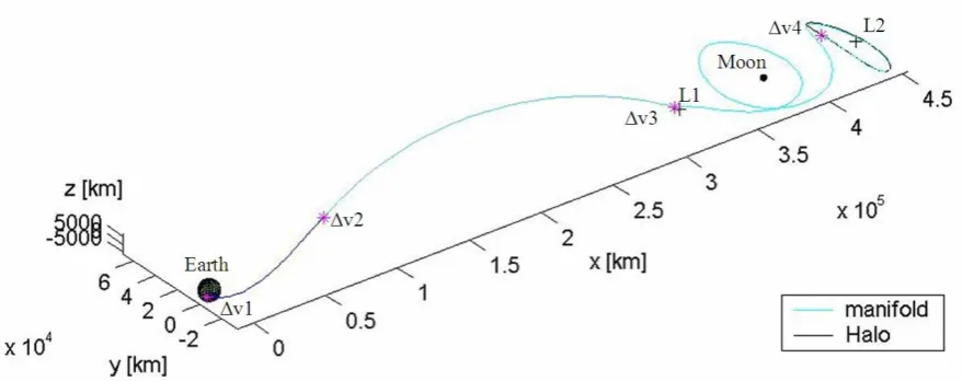
Figure 4 shows the obtained transfer trajectory in the synodic reference frame. ∆v values and trajectory segments time intervals are shown respectively in Table 3 and Table 4.
Table 3: Earth-L2 transfer ∆v
∆v to change the orbit plane 0.000097 m/s
∆v for transfer injection 666.97 m/s
∆v2 0.0039 m/s
∆v3 593.36 m/s
∆v4 0.02918 m/s
Total transfer ∆v 1260.34 m/s
Statistical ∆v 126 m/s
A 10% margin has been added to the total Δv in order to take into account statistical correction manoeuvres and gravity losses.
Table 4: Earth-L2 transfer timeline
Transfer starting time t0 Time following the first ∆v t0 + 0.42 d Time following the second ∆v t0 + 3.4 d Time on the manifold t0 + 31.54 d Total transfer time 31.52 d
3.3. Launch and phasing orbit
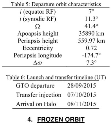
[image:6.595.75.520.96.270.2]since the date of launch, as a secondary payload, can not be decided, various launch opportunities, which generate different mission timelines, have been considered. One of these is reported in Table 5 and Table 6:
Table 5: Departure orbit characteristics i (equator RF) 7° i (synodic RF) 11.3°
Ω 41.4°
Apoapsis height 35890 km Periapsis height 559.97 km
Eccentricity 0.72 Periapsis longitude -174.7°
ω
Δ 7.3°
Table 6: Launch and transfer timeline (UT) GTO departure 28/09/2015 Transfer injection 07/10/2015 Arrival on Halo 08/11/2015
4. FROZEN ORBIT
The primary aim of the carrier is to transport the three landers close to the surface of the Moon, where it will perform a thrust braking manoeuvre. In addition it has to perform other two operations: a pre-landing surface mapping and a Moon gravitational field determination experiment.
The former requires an altitude lower then 600 Km to meet the camera resolution constraint and an inclination ideal to cover the larger portion of far side area. The latter requires an altitude lower then 500 Km to
avoid high third body disturbances, a high inclination in order to allow the most complete coverage.
These reasons motivated the choice of a frozen orbit. Konopliv’ spherical harmonics model with up to 20 harmonic coefficients have been used. Target orbit’s parameters, shown in Table 7, have been chosen in order to satisfy both the mapping and the gravitational experiment requirements.
5. WSB TRANSFER DESIGN
A WSB transfer was chosen for the carrier since a transfer via L1 of Earth-Moon to the required frozen orbit resulted to have an excessive cost.
The trajectory design process split the orbit in two main branches: the former is propagated forward in time from the Earth parking orbit while the latter is integrated backward in time from a lunar orbit of appropriate inclination. The two branches are linked in the WSB where in general an additional Δv manoeuvre is required to match the velocity. For this problem a first guess solution has been found with the same procedure presented in [6], then
Table 7: Carrier frozen orbit parameters i 90°
rP 1838 km (h = 100 km) e 0.03
[image:7.595.78.271.369.584.2]the resulting solution has been optimized with the software DITAN [26], an algorithm that transcribes the equation of motion with a direct finite element method and solves the resulting constrained transcription (DFET) non linear programming problem with a SQP algorithm.
[image:8.595.315.527.96.192.2]Two WSB transfers, satisfying the requirements, have been found (Table 8): the first one is slightly more expensive than the second one, but the latter is less sensitive to a variation in the initial conditions at the Earth. A further analysis has shown that similar launch opportunities occur every 6 months.
Table 8: WSB transfer timeline (UT)
Transfer 1 2
Departure from
LEO 25/09/2015 04/10/2015
Arrival in WSB 01/11/2015 23/10/2015 Lunar orbit
injection 13/01/2016 08/01/2016
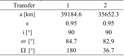
Table 9 shows the cost of the required impulsive manoeuvres: ∆v1 allows the WSB transfer injection from LEO, ∆v2 is imposed in the WSB; after that the carrier is captured by the Moon, in an elliptical orbit, whose characteristics in an equatorial reference frame are showed in Table 10. At the pericentre, ∆v3 is needed to circularize the orbit and finally
[image:8.595.65.286.272.363.2]∆v4 is the impulse to get into the frozen orbit.
Table 9: WSB transfer ∆v
Transfer 1 2
∆v1 [m/s] 3121.0 3073.0
∆v2 [m/s] 22.1 1.0448
∆v3 [m/s] 648.2 645.5038
∆v4 [m/s] 24. 3 24. 3
Total ∆v2 [m/s] 3815.4 3743.8
∆v [m/s] 138.1 130.9
Even in this case, a 10% margin has been added to the total Δv in order to take into account statistical correction manoeuvres and gravity losses.
Table 10: Elliptical lunar orbit characteristics
Transfer 1 2 a [km] 39184.6 35652.3
e 0.95 0.95
i [°] 90 90
ω [°] 84.7 82.9
Ω [°] 180 36.7
In Figure 5 WSB transfers made with DITAN are represented.
5.1. Launch and phasing orbit
The carrier is launched as primary payload on a Dnepr-M. After the launch (Baikonur, 46° N, 63° E, Kazakhstan), Dnepr will inject the carrier on a LEO parking orbit (h=500km) with inclination of 63.5°. Then the upper stage (Star 48A by Thiokol) will inject the carrier into the Earth-WSB transfer leg.
6. DEORBITING AND LANDING
After the end of the mapping operations and the gravitational experiment, the carrier will wait the optimal landing conditions: best lighting and correct sub-satellite point. The ground control of the mission can choose the landing area and determine the timing of the commands to transmit to the spacecraft.
The descent phase will require two major manoeuvres: the first one will be performed by the carrier while on the frozen orbit to start the descent. The second one, performed while approaching the surface, reduces the descent velocity to zero at an altitude of 35 m. After the deployment of the landers the carrier crashes on the surface with an impact velocity of ~10 m/s.
A bang-off-bang control strategy has been optimized with a SQP subject to the following constraints:
• A coasting elliptical trajectory is designed to phasing the manoeuvre with the motion of the goal area;
• The overall trajectory shall have an altitude greeter than 20 km in order to fly over the mountains, except for the final phase;
[image:8.595.70.281.511.623.2]• At the end of the last phase, the spacecraft must have burned out all the propellant in order to avoid risk of explosion during the crash. However a margin has been considered in order to target more landing zones.
• The overall manoeuvres are performed by only two of the four main engines: in case of failure it is possible to inject the other engines and continue the deceleration. The initial conditions for the integration are the position and the velocity of the carrier on the frozen orbit and the dry mass of ~300 kg. The resulting trajectory is characterised by a total propellant mass of ~270 kg and a total time of 1 h 9 min, for a total ∆v of ~2080 m/s.
CONCLUSIONS
In this paper the trajectory optimisation process for the Hevelius mission has been described. Different methods and computational tools has been exploited and combined. The task of finding a good initial guess for the orbiter transfer has been difficult; a low cost trajectory has been found by exploiting GA and a local optimization with a sequential quadratic programming algorithm. This has permitted the design of a microsatellite of 120 kg class.
Further studies in mission analysis should include:
• A finer analysis of the launch windows. • Failure analysis of the orbit injections. • Orbit maintenance manoeuvres schedule.
ACKNOWLEDGMENTS
The mission “Hevelius” has been designed at the “Politecnico di Milano” from a group of students during the class of “Space System Design” and with the supervision of Prof. Massimiliano Vasile.
The authors would like to thank the whole Hevelius team and everyone who contributed to the realization of the project with his work and help.
A copy of the report can be asked to the authors, at the Aerospace Department of the “Politecnico di Milano” or on the internet [15].
REFERENCES
[1] Belbruno E. A., "Lunar capture Orbits, a Method of Constructing Earth-Moon trajectories and The Lunar GAS Mission", AIAA, 87-1054.
[2] Belbruno E. A., Miller J. K., "A Method for The Construction of a Lunar Transfer Trajectory Using Ballistic Capture", AAS, 91-100.
[3] Belbruno E. A., Miller J. K., "Sun-Perturbed Earth-To-Moon Transfers With Ballistic Capture", Journal of Guidance Control, and Dynamics.
[4] Belbruno E. A., Humble R., Coil J., "Ballistic Capture Lunar Transfer determination for the US Air Force Academy Blue Moon Mission", AAS, 97-171.
[5] Betts J. T., "Survey of Numerical Methods for Trajectory Optimization", Journal of Guidance, Control and Dynamics, v. 21, n. 2, Mar-Apr 1998, 193-207.
[6] Comoretto G., Ercoli Finzi A., Vasile M., “Ottimizzazione di trasferimenti WSB Tramite Combinazione di Metodi Euristici e Sottoprogrammazione Quadratica”, 2000.
[7] Davis L., The Handbook of Genetic Algorithms, Van Nostrand Reingold, New York, 1991.
[8] Farquhar R. W., “A Halo-Orbit Lunar Station”.
[9] Goldberg D., Genetic Algorithms in Search, Optimization, and Machine Learning, Addison-Wesley, 1989.
[10] Gill P.E., Murray W., Saunders M. A., Wright M. H., "Procedures for Optimization Problems with a Mixture of Bounds and General Linear Constraints", ACM Trans. Math. Software, Vol. 10, pp 282-298, 1984.
[11] Gill P.E., Murray W., Wright M. H., “Numerical Linear Algebra and Optimization”, Vol. 1, Addison Wesley, 1991.
[13] Gómez G., Marcote M., Masdemont J., "Trajectory Correction manoeuvres in the Transfer to Libration Point Orbits".
[14] Hartmann J. W., Coverstone-Carroll V. L., Williams S. N., “Optimal Interplanetary Spacecraft trajectories via a Pareto Genetic Algorithm”, Journal of the Astronautical Sciences, v. 46, n. 3, Jul-Sept 1998, 267-281.
[15] “Hevelius - Lunar Microsatellite Mission”, Final Report, http://www. hevelius.altervista.org, 2004.
[16] Holland J., Adaptation in natural and artificial systems, The University of Michigan Press, Ann Arbor, 1975.
[17] Howell K. C., Mains D. L., Barden B. T., “Transfer Trajectories From Earth Parking Orbits to Sun –Earth Halo Orbits”, AAS-94-160, AAS/AIAA Spaceflight Mechanics Meeting, Cocoa Beach, FL, February 14-16, 1994.
[18] Koon W. S., Lo M. W., Marsden J. E., Ross S. D., “Shoot The Moon”, AAS/AIAA Astrodynamic Specialist Conference, Florida, 2000, AAS 00-166. [19] Koon W. S., Lo M. W., Marsden J. E.,
Ross S. D., "Constructing a Low Energy Transfer Between Jovian Moons", 1 Aug 2000, 1-14.
[20] Michalewictz Z., Genetic Algorithms + Data structures = Evolutionary Programs, AI series, Springer-Verlag,New York, 1994.
[21] Richardson D. L., "Halo Orbits Formulation for the ISEE-3 Mission", Journal of Guidance and Control, v. 3, n. 6, Nov-Dec 1980, 543-548.
[22] Richardson D. L., “Analytic Construction of Periodic Orbits About the Collinear Points”, Celestial Mechanics 22 (1980) 241-253.
[23] Starchville T. F., Melton R. G., "Optimal Low Thrust Trajectories to Earth-Moon L2 Halo Orbits (Circular Problem)", AAS/AIAA Astrodynamics Specialist conference, 4-7 Aug 1997.
[24] Starchville T. F., “Optimal low-thrust Trajectories to Earth-Moon L2 Halo Orbits (Circular Problem)”, AAS/AIAA Astrodynamics Specialist Conference, 4-7 Aug 1997.
[25] Topputo F., Vasile M., Ercoli Finzi A., "An Approach to the design of Low Energy Interplanetary Transfers Exploiting Invariant Manifolds of the Restricted Three-Body Problem", 14th AAS/AIAA Space Flight Mechanics Conference, 8-12 Feb 2004, 1-20.