On-board Timeline Validation and Repair: A Feasibility Study
M. Fox
and
D. Long
Department of Computer and Information Sciences University of Strathclyde, Glasgow, UK
L. Baldwin
and
G. Wilson
and
M. Woods
SciSys Ltd, Clothier Road, Bristol, UK
D. Jameux
European Space Agency (ESA) European Space Research and Technology CentreNoordwijk, The Netherlands
R. Aylett
Herriot-Watt University, Edinburgh, UK
Abstract
We report on the progress and outcome of a recent ESA-funded project (MMOPS) designed to explore the feasibility of on-board reasoning about payload timelines. The project sought to examine the role of on-board timeline reasoning and the operational context into which it would fit. We framed a specification for an on-board service that fits with exist-ing practices and represents a plausible advance within sen-sible constraints on the progress of operations planning. We have implemented a prototype to demonstrate the feasibility of such a system and have used it to show how science gath-ering operations might be improved by its deployment.
Introduction
Communication to distant landers is restricted, both by availability of a communication window and by the time it takes for a signal to pass from transmitter to receiver. This makes it essential to construct plans for the activities of a distant spacecraft, often spanning several hours or days of otherwise unsupervised activity. As has frequently been ob-served, plans rarely survive contact with reality unscathed. Plans must be constructed using predictions about the out-come of activities of the spacecraft and also predictions of the behaviours and reactions of the surrounding environ-ment. These predictions can diverge from the actual be-haviours when a plan is executed. In typical currently de-ployed systems, plan failure will (depending on the severity of the failure) lead to the spacecraft entering a safe mode and awaiting further instructions, having aborted execution of the remainder of the plan. This response shares an important characteristic with the models on which the plans are based from the outset: they are conservative. That is, both the pre-dictions about the activities of a spacecraft and the response to failures in those predictions act to limit and constrain the science gathering operations of the spacecraft. To illustrate this conservatism, consider that it is now estimated that So-journer spent at least 50% of its time idle, awaiting further instructions, either because it had completed its planned ac-tivities and had nothing left to execute, or because it had entered safe mode following a failure in some activity. Even the immensely successful Mars Exploratory Rovers (MER) mission has been extremely cautious: the original planned mission lifetime for the rovers was only 90 sols, yet they have now been active for more than 850 sols. Even so, they
have travelled no more than 7 kilometers in the nearly three years of mission activity. Despite great improvements in the support technology for the planning of MER operations
(Ai-Changeet al.2003), plans remain conservative and plan
ex-ecution failures have caused many days of lost science gath-ering over the lifetime of the mission.
In this paper we describe the Mars Mission On-board Planning and Scheduling (MMOPS) project, in which we explored the construction of a prototype system that would help to address the loss of science caused by conservative mission planning and plan failure. Our prototype has been
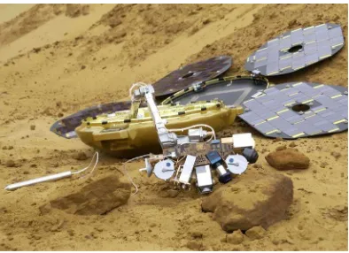
constructed to work with the Beagle 2 (Blakeet al. 2004)
hardware (see Figure 1), since the on-board software (OBS) and simulator were already available to the team. As part of the project, we have also considered the use of our approach for a mobile lander, such as the planned ExoMars rover.
Our approach has been to design a system that could be deployed on-board a remote spacecraft, granting the craft some measure of autonomy. Other space missions have also
explored this possibility, with some success (Chien et al.
2004; J¨onsson et al. 2000). In our work we have not
at-tempted to construct a system in which planning is devolved to the on-board system. Instead, it remains under the control and supervision of the ground operations personnel. The on-board system is designed to manipulate plans (timelines) constructed on the ground, handling three problems that we consider to be central to execution issues on spacecraft:
• Plan failure isolation. When a plan contains an activity
that fails, or that it is predicted will fail, the first concern is to isolate the consequences of that failure and to protect execution of the remainder of the plan.
• Over-subscription. When a plan contains more activities
than it is predicted that there are resources available to support, activities must be removed from the timeline in order to bring it back within safe bounds. This situation includes both consumable resources such as power and fixed resources such as instruments.
• Under-subscription. Either as a consequence of failure
isolation, or conservative estimates for plan execution, if it is predicted that more resource will be available than was expected before plan execution began, this resource can be absorbed to perform additional activities. We call
de-Figure 1: Beagle 2
scribed in more detail below.
The system we have developed performs Timeline Val-idation, Control and Repair (TVCR). These three services provide the foundation of the management of the problems identified above. The design of the system allows these ser-vices to be invoked incrementally, so that additional func-tionality is called on as ground personnel gain confidence in the behaviour of TVCR.
Background
On December 25th, 2003, a small lander, travelling with the Mars Express orbiter, was expected to land on Mars sur-face. Unfortunately, mirroring the fate of many other at-tempts to land probes on Mars, Beagle 2 was unsuccessful. Various explanations of its failure have been proposed, in-cluding the possibility that the density of the Martian atmo-sphere is not as high as had been thought and, as a result, the parachute-brake failed to slow the lander sufficiently be-fore impact. Considerable expertise was built up around the Beagle 2 systems, including a partial domain model for hu-man planning operations, and this formed the core of an ini-tial project to exploit planning technology to support mixed-initiative and partially automated planning for the lander
op-erations (Woodset al. 2003) and, from that, the project
de-scribed in this paper. Beagle 2 was a static lander, equipped with a jointed arm carrying an array of scientific instruments in a “paw” at its end. Included in the paw was a mole capa-ble of drilling into soil around the lander to a distance of more than 2 meters, to retrieve soil samples for gas analysis on board the lander. Beagle 2 was, essentially, a geological survey system, capable of performing an array of geological and environmental measurements in its immediate surround-ings.
All lander operations are constrained by power availabil-ity, provided by solar energy with a battery for storage, and by temperatures. Planning lander operations involves man-aging constraints on continuously changing quantities (the generated power levels and temperatures), scheduling the use of resources, planning the movement sequences of the arm and use of the instruments. Human operations plan-ners were to have carried out the planning for Beagle 2
in a complex process involving scientists, providing mis-sion goals and the operations to achieve them, and lander operations personnel, concerned with lander security and, therefore, the power resources and internal lander monitor-ing systems. When we became involved in the project we discovered that the existing partial domain description was
in a form that closely resembled PDDL2.1 durative action
descriptions (Fox & Long 2003). It was possible to translate
the description intoPDDL automatically using a simple
au-tomatic translator. The domain encoding began with over 50 actions and this has increased to nearly 70 actions following further domain analysis.
Power is the most important continuous factor in the op-erations of the lander. The lander operates close to margins and the model of the solar generation and the battery charg-ing profiles are vital in determincharg-ing when operations can be planned. The management of battery and solar power is suf-ficiently close to the margins of operational envelopes that plans must interact with the continuous changes involved in the physical system rather than with abstractions into coarse-grained simple step-function changes. Of course, with suf-ficiently small time-steps a step-function model can approx-imate the continuous change adequately, but it is infeasible to attempt to model this level of granularity explicitly in the planning domain description. Therefore, this problem de-mands that the planner (human or otherwise) has access to a sufficiently detailed model of the continuous changes that affect the power systems.
Ground-based Planning, On-board Repair
Our preliminary investigations (Woods et al. 2003)
con-vinced us that, while on-board planning technology has an important role to play, there are important reasons why, in the short-term, fully automated plan construction is not the most important objective. The first reason is that on-board resources are extremely constrained, so both CPU and mem-ory availability is likely to prevent realistic planning technol-ogy from being deployed on deep space probes in the near future (notwithstanding the important success in the Remote
Agent Experiment (J¨onssonet al. 2000)). The second
rea-son is that neither scientists not operations perrea-sonnel (those currently responsible for planning of spacecraft operations) are willing to relinquish their tight control over operations until significantly more experience and trust in automated technologies has been built up. Therefore, our goal has been to provide an on-board “planning assistant”, providing sup-port to the operations personnel responsible for constructing plans on the ground. The role of the assistant is to adjust and repair plans on-board when circumstances make it im-possible execute the plans constructed on the ground. An essential constraint on this behaviour is that the plans that are manipulated on-board are all built on the ground by op-erations personnel.
Domain Models and Plan Fragments
[image:2.612.76.273.52.195.2]form the building blocks of plans in terms of their precon-ditions and effects. Preconprecon-ditions and effects are evaluated with respect to a model of the state of a system and its envi-ronment. The state is represented by a collection of propo-sitions asserting both logical status and also numeric values of metric properties. In our work we have used PDDL (Fox & Long 2003) as our modelling language, since it offers us access to a range of research tools already constructed for the construction and analysis of plans and domains.
Although PDDL offers an expressive language for mod-elling the behaviour of individual actions and their interac-tions with other acinterac-tions, it does not currently offer a way to express several other important constraints on the structure of plans. For example, Beagle 2 was equipped with a rock grinder and various imaging tools: it is standard scientific methodology to perform experiments so that the least inva-sive investigations are performed first, following them with those that might change the target of investigation physi-cally or, finally, chemiphysi-cally. Thus, the grinder would not be deployed until after images of a target had been captured. This constraint is not a logical constraint on the performance of these actions — clearly, it is perfectly possible to grind a rock before taking any images of it. Instead, this is a methodological constraint on the actions in a plan. Although there are techniques that would allow such constraints to be modelled in PDDL, the fact that these constraints govern not the way in which actions can be performed but the circum-stances under which it would be appropriate to perform them is very significant. In particular, methodological constraints may be relaxed under exceptional circumstances, while log-ical constraints cannot be.
AI planning research has been primarily focussed on the construction of plans for goals that specify the conditions that should be achieved in the final state. In the context of space probe plans we found that this was not always the most convenient way to express the purpose of plans. Of-ten, a plan is intended to perform a series of experiments and the simplest way to express their goals is to say which actions they are designed to perform rather than to express the goals in terms of the states that these actions achieve. One reason for this is that the effects of a science gathering activity seen from the perspective of the on-board state are typically to add data to some internal data buffer. The on-board state is not really any different if the data is acquired from a spectrometer or from a camera, but to support the expression of goals in terms of state conditions would re-quire that a distinction be made between the various sources of data, including not only the instrument but also the tar-get. This complicates the model and is counter intuitive for operations personnel when describing plans.
To address these problems we introduced a separate way to capture information about the structure of a plan and its purpose. Our objective was to provide a tool that would allow operations personnel to record information about the structure of a plan — information that was already known to them but has previously not been formally captured or recorded. Essentially, we wanted to capture the information that might be exchanged informally between (human) plan-ners during the initial construction of a plan. This
informa-tion includes:
• Plan structure. In order to identify the organisation of
a plan into coherent blocks of activity we allowed plans
to be divided intoplan fragments. A plan fragment is a
group of actions that are together in a plan to coordinate and achieve a single objective. The group forms a co-herent unit of related activities, such as preparing equip-ment, deploying it and gathering data from it before stow-ing it again. The point in identifystow-ing these structures is that these actions are in a plan because of their mutual in-tegrity. If, for example, an instrument is known to be non-operational then there is no benefit in deploying it and stowing it, even if those actions are logically independent of the status of the instrument.
• Ordering constraints. When it is important that one
ac-tivity should precede or succeed another, but this condi-tion is not a logical constraint on the interaccondi-tions of these activities then we record it as a plan constraint. Such constraints might hold between individual activities or
be-tween entire fragments. We distinguish bebe-tweenordering
dependencies, where the two constrained elements should
either both appear in a valid execution of a plan, or else
neither appear, andconditional orderings, where the two
constrained elements must appear in a particular order if they are both executed.
• Timing constraints. Activities or fragments can be
iden-tified as requiring to be executed during darkness or
dur-ing daylight. They can also be marked asfixed, meaning
that the time at which they are to be executed cannot be changed. This is typical for communication activities that must synchronise with communication windows shared by orbiters or ground-based transmitters.
• Mutual exclusion constraints. These constraints prevent
two activities, or fragments, from coexisting in the same timeline. This constraint can be useful in triggering the use of diagnostic activities where they are inappropriate when the corresponding instrument is functioning, but they should be included in the plan exactly when the activ-ities using the instrument have failed (and therefore have not been executed in the current timeline).
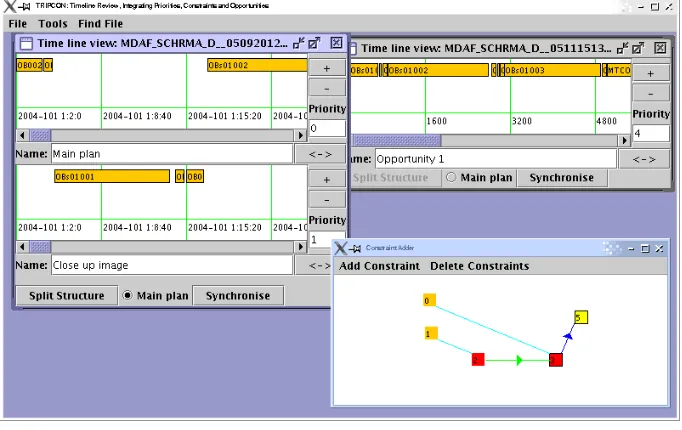
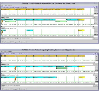
Figure 2 shows the interface to our prototype tool, CON
-TOOL, developed for this project. It presents a simple view
of the timeline and allows selection of elements to be split into fragments. The entry of constraints is managed in the smaller window showing the small coloured and number-coded blocks representing activities and fragments. An
im-portant aspect of the use of CONTOOL is the identification
of plan fragments. The fragments that form the main time-line are the building blocks that form the primary scientific experiments for that period. However, additional fragments can be created and included in the data sent to the lander, identifying optional additional experiments that might be
performed. These are calledopportunities (an example is
shown in the upper right window of the screenshot). Each
opportunityis a self-contained scientific experiment,
Figure 2: The plan fragment and constraint editing tool.
allows ground staff to propose useful additional activities that scientists would like to see executed but which have not been selected for the primary timeline for that period. These opportunities are used to reduce the problem of under-subscription: when the lander completes the primary time-line with a significant margin of unused resource — a situ-ation that can often occur because of conservative assump-tions made during planning — the excess can be deployed to achieve bonus experiments in the form of opportunities. Similarly, if failure of parts of the primary timeline leaves the lander with freed resource, opportunities can be used to achieve some scientific return from the resource that would otherwise be wasted.
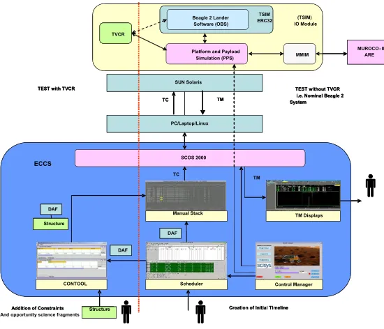
System Architecture
Our system architecture is illustrated in figure 3. The lower part of this diagram shows the ground-based operations planning tools. These include standard timeline planning tools used in earlier ESA missions. The interface between these tools and the lander is achieved via the generated telecommands. The lander is represented using the original Beagle 2 on-board software (OBS), running in an ERC32 emulator on a Sun Solaris machine. Hardware elements of the lander are simulated in software. The Beagle 2 OBS was modified to allow communication with the additional module, TVCR. This module was constructed using several existing software components and was not, therefore, built with a view to on-board deployment. As a consequence, the most efficient connection with the OBS was determined to be through a page of external memory which could be written-to and read-from by the emulated ERC32. TVCR ran as an external library on the Solaris machine, invoked whenever the external memory page was written-to by the OBS.
TVCR: An on-board planning assistant
TVCR is built around our plan validation system,
VAL (Howey, Long, & Fox 2004a; 2004b; Fox, Howey,
& Long 2005), coupled with a plan-execution architecture,
originally developed for robot control (Coddington et al.
2005). The execution architecture is not critical to the be-haviour of TVCR, but was a convenient framework in which to work. TVCR receives three types of requests from the
OBS:validate,controlandrepair. The validaterequest is
issued when a new timeline has been transmitted to the lan-der. The OBS issues the request before the timeline begins execution. The timeline is then validated using the on-board state and model. The model is a PDDL (McDermott & the AIPS’98 Planning Competition Committee 1998) descrip-tion of the domain, using continuous funcdescrip-tions that very closely approximate the solar generation and battery use
curves. We discuss the model below. Thecontrolrequest is
issued periodically by the OBS, during execution of a time-line, in order to monitor the continuing evolution of the tra-jectory. In our prototype the control request frequency was set at 0.1 Hz, but this could be dynamically adjusted to suit the demands on CPU and memory, as well as the granular-ity of current activities. In response to this request, TVCR can revalidate the plan, but this depends on how close to the next critical transition in the activities of the system TVCR judges the system to be. In particular, TVCR validates the timeline following initiation of a new activity and approach-ing the end of an activity. It will also validate the timeline in between activities if there is sufficient gap before the next activity will begin. Essentially, once this gap is small, it is not possible for TVCR to respond to an anticipated activ-ity failure before the failure would be triggered anyway on attempted dispatch to the lander executive.
The final request, repair, is only issued by the OBS
vali-SUN Solaris
PC/Laptop/Linux
SCOS 2000
Scheduler CONTOOL
TM Displays Manual Stack
Structure
TC
TM Platform and Payload
Simulation (PPS)
TEST with TVCR TEST without TVCR
i.e. Nominal Beagle 2 System
Addition of Constraints And opportunity science fragments
Creation of Initial Timeline (TSIM) IO Module
ECCS
MMIM
MUROCO - II ARE
Control Manager SUN Solaris
PC/Laptop/Linux
SCOS 2000
Scheduler CONTOOL
TM Displays Manual Stack
DAF DAF DAF
DAF DAF DAF DAF
Structure DAF DAF
Structure Structure
Structure Structure
TC
TC TMTM
TC
TM Platform and Payload
Simulation (PPS) Beagle 2 Lander Software (OBS)
TSIM ERC32 Beagle 2 Lander Software (OBS)
TSIM ERC32
TVCR TVCR
TEST with TVCR TEST without TVCR
i.e. Nominal Beagle 2 System
Addition of Constraints Creation of Initial Timeline
(TSIM) IO Module
ECCS
MMIM
MUROCO - II ARE
[image:5.612.168.443.57.293.2]Control Manager
Figure 3: The system architecture, showing both ground and lander segments.
dateorcontrol) has identified a potential failure in the time-line. In fact, when TVCR identifies such a potential flaw it does not immediately signal the fact to the OBS (although it is logged). Instead, the problem is signalled when TVCR judges that there is a window during which it would be ap-propriate to respond. One reason for this is that anticipated failures far into the future might be countered by activities in the nearer term completing well within the (usually conser-vative) estimated resource requirements. Reacting too early to anticipated plan failure can be as damaging as failure to act. TVCR continues to monitor the timeline execution and the anticipated failure point, based on the type of failure that is expected, until the point it considers appropriate to alert
the OBS. Once OBS issues arepairrequest, TVCR is
sanc-tioned to act to repair the timeline.
TVCR Acting to Repair the Timeline
TVCR is intended to operate within tightly constrained re-source limits: processor cycles and memory availability are both severely restricted. For this reason, we have adopted a strategy that is based on a hierarchy of responses, starting with a simplest response which is to repair a damaged time-line by removing the activities from the current timetime-line that are affected by the observed failures. This process involves first removing the fragments in which the affected activities lie, using the structure identified by the operations personnel
through CONTOOL. The impact of these removals is
prop-agated through the constraints which were also entered by operations personnel. The resulting structure is revalidated and, if there remains a violation of resource demands, fur-ther components are removed, using the priority levels set on the ground to determine the order in which fragments are taken out of the timeline. Where there are dependencies
The enhancements of the timeline are performed by iden-tifying a subset of possible opportunity fragments that might be added to the timeline. This set is pruned to include only those for which dependencies are satisfied (or mutual ex-clusions violated) and for which there is sufficient avail-able resource (within the limits of the original primary time-line). The opportunities are then ranked in priority order. In general, there are relatively few opportunities to consider, but there can be choice between alternatives. In particular, when multiple opportunities are awarded the same priority, the choice between them must consider alternative resource demands and the interactions between the alternatives and other outstanding opportunities. In order to maintain a tight bound on memory and CPU demands the search is resolved heuristically, using a greedy selection. This could obviously be improved if resources were to be less constrained, but our experience suggests that greedy choice works well. It is worth recalling that the repair strategy is only applied in situations where resources would otherwise go unused, so even a sub-optimal enhancement of the timeline offers ben-efits over the timeline without intervention.
The hierarchy of extensions to the timeline begins by con-sidering the addition of opportunity fragments to the time-line. It should be noted that when a timeline is modified, either by the removal or by the addition of fragments, then it is generally the case that some additional linking activities are required between the ends of the newly adjacent parts of the timeline. TVCR has a special-purpose planner de-signed for this job, which only considers a very small subset of activities (those relevant to this linking behaviour). This problem is very highly constrained and involves no search, but the linking activities must be known in order to deter-mine the costs of execution of new fragments. Following the simple addition of fragments, the next possibility that is con-sidered is the rescheduling of activities in order to open up wider windows of opportunity for execution of longer activ-ities. This is particularly useful when small overlaps prevent an opportunity from fitting into a gap between other activ-ities in the timeline. The rescheduling considers only the possibility of sliding activities along the timeline and this is restricted by any constraints stipulated on activities by op-erations personnel, including activities that are locked (such as communications activities) or that must occur in certain lighting conditions.
In principle, the addition of opportunities can open up new opportunities, through satisfaction of dependencies, so the set of opportunities can be modified after each enhance-ment of the timeline. The process of generation of further enhancements is restricted by the time, CPU and memory resources available to the repair process, but TVCR will continue to explore the hierarchy of extended timelines until notified that there is no further resource, or until no further improvement can be found. In our test cases there were rela-tively few opportunities to consider and reasoning resources were never a limiting factor.
The Domain Model and Timeline Validation
When we began work on the construction of a PDDL do-main model, we started with a pre-existing model built by
the scientists working on the Beagle 2 project. We found that this model was so similar in form to PDDL that a simple script provided us with an initial translation into PDDL. We concluded that the level of abstraction we require to support plan validation using our PDDL model is an appropriate and natural one for operations personnel and that it corresponds well to the level at which timeline activities are planned in actual missions. The model is based on a pre- and post-condition description of activities, most of which are dura-tive actions. A few actions, such as turning on the torch attached to the PAW, are not best captured as durative ac-tions. The model also required an appropriate power model and temperature model. In these cases we found that the extensions forming PDDL+ (Fox & Long 2006),
compris-ing the addition ofprocessesandeventswere an appropriate
basis for modelling the domain behaviours. Torch activi-ties are modelled as instantaneous actions (turning on and turning off the torch), with a process consuming power be-tween the two. The power model is constructed using con-tinuous processes that capture an approximate, but realis-tic, model of solar power generation and of battery state of charge. Our model of temperature is not continuous: we were supplied with a discretised model of the temperature of various nodes on the lander structure at hourly intervals. This is used to construct a series of timed assertions in the initial state of each planning problem instance. We chose to adopt the discretised model in this case in order to demon-strate that our approach can handle both a continuous and a discretised model. In both cases the model is an approxi-mation, although with different levels of discrepancies, and one of the key issues in managing the plan validation is to ensure that the activity models are conservative with respect to these approximations.
Validation of a timeline involves projection of the state through a series of models of activities representing the
timeline. This process involves confirming that the
Execute plan i Return data i Generate plan j Check Lander state Time FCT Plan Evaluate Exploit Support Teams Send plan j Execute
Sol i Sol j Sol l
Check plan h execution Generate science products h Analyse science results h
MPT MET GOT
Execute plan j
Return data j Generate plan k Check Lander state FCT Send plan k
Check plan i execution Generate science products i Analyse science results i
MPT MET GOT
Sol k
Execute plan k Return data k Generate plan l Check Lander state FCT Send plan l
Check plan j execution Generate science products j Analyse science results j
MPT MET GOT
Execute plan l
Return data l Generate plan m Check Lander state FCT Send plan m
Check plan k execution Generate science products k Analyse science results k
MPT MET GOT
21 22 23 24 25 26 27 28 29 30 31 33
[image:7.612.124.496.63.334.2]99 => Experiment 99
Figure 4: Normal operations sequence.
Execute
plan i Return data i Generate plan j Time FCT Plan Evaluate Exploit Support Teams Send plan j Execute
Sol i Sol j Sol l
Generate science products h Analyse science results h
MPT MET GOT
Return data j Generate diagnostic plan k FCT Send plan k Generate science products i Analyse science results i
MPT MET GOT
Sol k
Execute diagnostic
plan k Return data k
FCT
Send no plan
MPT MET GOT
Return data l Generate repair plan m FCT Send plan m
MPT MET GOT
Bang! Analyse failure Identify diagnostics Analyse diagnostic data Identify repairs Analyse failure Check Lander state Check plan h
execution
Check Lander state Check plan i
execution
Check Lander state
Check Lander state Check plan k
execution Generate reduced plan l Execute reduced plan l Generate science products i Analyse science results i
21 S 24 26 27
99 => Experiment 99 Z => Diagnostic Z
[image:7.612.124.495.388.663.2]Execute
diagnostics & opportunities Execute
plan i Return
data i Generate plan j
Time
FCT
Plan
Evaluate
Exploit
Support
Teams
Send plan j
Execute
Sol i Sol j Sol l
Generate science products h
Analyse science results h
MPT MET GOT
Generate repair plan k
FCT Generate
science products i
Analyse science results i
MPT MET GOT
Sol k
FCT MPT MET GOT
Generate plan m
FCT MPT MET GOT
Bang!
Analyse science results j
Analyse science results k Generate
science products j
Generate science products k Execute viable parts of
plan j & opportunities Return data j Send plan k
Execute repair plan k Return data k Send plan l Generate plan l
Execute plan l
Return data l Send plan m Generate diagnostics
& opportunities
Check Lander state Check plan h
execution
Check Lander state Check plan i
execution
Check Lander state Check plan j
execution
Check Lander state Check plan k
execution
Analyse diagnostic
data Identify repairs Generate diagnostics
& opportunities
Generate diagnostics & opportunities
Generate diagnostics & opportunities
21 S Q 24 K M 22 23 25 26 27
[image:8.612.118.495.55.326.2]99 => Experiment 99 Z => Diagnostic or Opportunity Z
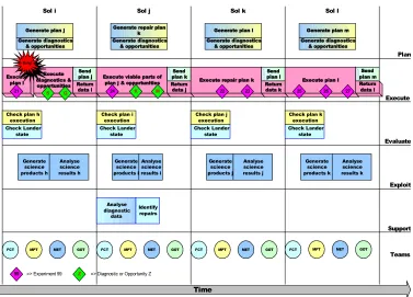
Figure 6: Operations sequence with on-board plan repair.
Evaluation
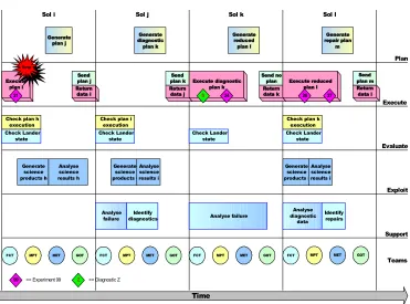
Evaluation of TVCR is complicated by the fact that its role is most important when the execution trajectory has performed unexpectedly. We were further constrained by the hardware simulation we were using: this did not simulate the detailed function of some instruments, making it very difficult to model failures in those subsystems. In order to understand the impact of an operational failure during timeline execu-tion, consider the schematics in figures 4, 5 and 6. Figure 4 shows the typical progression of operations, in which time-lines are planned during the day (sol) preceding their ex-pected execution (assuming an operational cycle of roughly one sol). At the end of each day the data generated by that day’s operations is downlinked for analysis and a new time-line is uplinked for execution in the following day. If there is an operational failure in this cycle (shown figure 5 imme-diately following activity 21) the ground staff will not be-come aware of it until the end of that day’s activities. The planned timeline for the next day will be downlinked be-fore the ground staff become aware of the problem in the current day’s activities. In the worst case, this timeline will no longer be executable, probably because the lander will have entered safe mode in response to the failure. Assum-ing that the ground staff now wish to execute diagnostics, they will have a first opportunity to perform new activities by the second day following the failure. It is likely that other activities might be included at this time, depending on the severity of the failure. Instrument repairs will then take place on the third day following the failure and normal
activity will be resumed only on the fourth day after the fail-ure. With TVCR (figure 6) the failure will (assuming the failure is not too severe) lead to the insertion of opportuni-ties into the timeline on the first day. These can include a diagnostic activity which would be constrained to be added to the plan only if the instrument operation had not been per-formed (that is, the diagnostics would be mutually exclusive with a successful operation of the instrument for which they were relevant). The planned timeline for the following day would almost certainly not execute directly following the disrupted cycle of operations, but parts of it might execute successfully and TVCR could insert additional opportunities to absorb the otherwise undersubscribed resources available on that day. Meanwhile, the ground staff, armed with the diagnostics, would be in a position to plan instrument re-pairs and continuation of the remaining science mission, so that by the second day following failure a full sequence of activities could be completed. Normal operations would re-sume fully on the third day, but the intervening period would have included a fully populated timeline, so that the mission would have continued to gather scientific data and complete diagnosis and repair of instrument failures.
missions personnel put the lander back into an operational state and resynchronise their view of its status with reality. It is in these cases where TVCR can help to recover what would otherwise be lost time and resources.
To explore the performance we generated a collection of scenarios, based around a common timeline, featuring two rock geology experiments. The primary timeline con-tained two M¨ossbauer spectrometer experiments, supported by imaging and rock grinding activities (see figure 7). We then considered a variety of possible failures. These in-cluded:
• A scenario in which the M¨ossbauer was assumed to have
failed prior to the timeline being uplinked. This might happen if the instrument had failed in an activity in the timeline immediately preceding this one, so that the fail-ure would be unknown to the ground staff at the time of construction of the new timeline.
• A scenario in which the M¨ossbauer failed during the first
activity in which it was used.
• A scenario in which there was insufficient battery charge
at the start of the plan to allow it to complete execution. In each case, TVCR performed as expected and repaired the timeline. Where a suitable opportunity was available, TVCR inserted it into the timeline, together with the neces-sary linking activities to create a complete, coherent time-line, which was then successfully simulated to conclusion. As can be seen in figure 8, the timeline executed when TVCR performed repair was significantly enhanced com-pared with the one executed without TVCR. In the upper case almost all of the timeline is abandoned without TVCR support. In both cases the timeline is repaired by removal of the damaged activity or activities and an opportunity is inserted into the timeline in the place of the first. This is an environmental sensing activity and relies on the PAW being placed into an appropriate attitude. This is achieved by the addition of some simple “glue” activities that reposition the PAW prior to execution of the fragment and then rejoin the execution of the original timeline at its conclusion.
A further dimension for evaluation is that of performance. In our tests, the validation of a timeline of approximately two sols of activity could be performed in less than 3 sec-onds using an estimated ERC32 processor speed, with repair in less than 6 seconds. Our prototype was not optimised for either memory or processor performance, but we consider this figure to be representative of the performance we can expect from TVCR.
Conclusion
We have successfully constructed a prototype system that acts as an on-board plan validation and repair system. We have used the prototype to demonstrate that on-board rea-soning about plans is a practical objective which is less am-bitious than full-scale planning, but that can grant huge ben-efits in terms of science return. Several features contribute to this. Firstly, an on-board system is best placed to monitor execution of a plan and react to failures in a timely and effec-tive way. Secondly, the very fact that plans can be brittle in
execution means that operations staff tend to be conservative in their construction of plans, leading to under-subscription of lander resources. The combination of these factors can lead to significant periods of downtime during deep space missions. An on-board planning assistant could exploit the slack during execution of a plan and adapt to plan failures in order to improve the scientific return.
References
Ai-Change, M.; Bresina, J.; Charest, L.; Hsu, J.; J´onsson, A.; Kanefsy, R.; Maldegue, P.; Morris, P.; Rajan, K.; and Yglesias, J. 2003. MAPGEN: Mixed intitive activity planning for the Mars Exploratory Rover mission. InProceedings of Demonstration Systems Track, ICAPS’03.
Blake, O.; Bridges, J.; Chester, E.; Clemmet, J.; Hall, S.; Han-nington, M.; Hurst, S.; Johnson, G.; Lewis, S.; Malin, M.; Mori-son, I.; Northey, D.; Pullan, D.; Rennie, G.; Richter, L.; Roth-ery, D.; Shaughnessy, B.; Sims, M.; Smith, A.; Townend, M.; and Waugh, L. 2004. Beagle2 Mars: Mission Report. Lander Operations Control Centre, National Space Centre, University of Leicester.
Chien, S.; Sherwood, R.; Tran, D.; Cichy, B.; Rabideau, G.; Cas-tano, R.; Davies, A.; Lee, R.; Mandl, D.; Frye, S.; Trout, B.; Hengemihle, H.; D’Agostino, J.; Shulman, S.; Ungar, S.; Brakke, T.; Boyer, D.; Gaasbeck, J. V.; Greeley, R.; Doggett, T.; Baker, V.; Dohm, J.; and Ip, F. 2004. The EO-1 autonomous science agent. InProceedings of AAMAS-04.
Coddington, A.; Fox, M.; Gough, J.; Long, D.; and Serina, I. 2005. MADbot: A motivated and goal directed robot. In Pro-ceedings of AAAI’05 (Intelligent Systems Demo).
Fox, M., and Long, D. 2003. PDDL2.1: An Extension to PDDL for Expressing Temporal Planning Domains. Journal of AI Re-search20:61–124.
Fox, M., and Long, D. 2006. Modelling mixed discrete-continuous domains for planning. Journal of AI Research forth-coming.
Fox, M.; Howey, R.; and Long, D. 2005. Validating plans in the context of processes and exogenous events. InProceedings of The 20th National Conference on Artificial Intelligence (AAAI-05). Howey, R.; Long, D.; and Fox, M. 2004a. Plan validation and mixed-initiative planning in space operations. InProceedings of the Workshop on ‘Planning and Scheduling: Bridging Theory to Practice’ (ECAI’04).
Howey, R.; Long, D.; and Fox, M. 2004b. VAL: Automatic plan validation, continuous effects and mixed initiative planning using
PDDL. InProceedings of 16th IEEE International Conference on Tools with Artificial Intelligence.
J¨onsson, A.; Morris, P.; Muscettola, N.; and Rajan, K. 2000. Plan-ning in Interplanetary Space: Theory and Practice. In Proceed-ings of International Conference on Artificial Intelligent Planning and Scheduling (AIPS).
MI
RCG Moss
XRS Mole
MI
RCG Moss
XRS Mole
[image:10.612.138.473.65.263.2]Comms Session
Figure 7: Base timeline showing instruments it commands.
[image:10.612.136.475.312.626.2]