Faculty of Engineering and Surveying
Understanding progressive collapse and its effect to structural design
A dissertation submitted by Keen Whale, Kwok
In fulfillment of the requirements of
Course ENG4111 and 4112 Research Project
towards the degree of
Bachelor of Engineering (Civil Engineering Major)
ABSTRACT
The objective of the report is to explore progressive collapse and define some particular terms and review current Building Codes about design methods. Several design methods will be reviewed. It aims to problem solving and work out a best solution for public safety and economical design.
University of Southern Queensland
Faculty of Engineering and Surveying
ENG4111 &ENG4112 Research Project
Limitation of Use
The Council of the University of Southern Queensland, its Faculty of Engineering and Surveying, and the staff of the University of Southern Queensland, does not accept any responsibility for the truth, accuracy or completeness of material contained within or associated with this dissertation.
Persons using all or any part of this material do so at their own risk, and not at the risk of the Council of the University of Southern Queensland, its Faculty of Engineering and Surveying or the staff of the University of Southern Queensland.
This dissertation reports an educational exercise and has no purpose or validity beyond this exercise. The sole purpose of the course pair entitled “Research Project” is to contribute to the overall education within the student‘s chosen degree program. This document, the associated hardware, software, drawing, other material set out in the associated appendices should not be used for any other purpose: if they are so used, it is entirely at the risk of the user.
Prof. Frank Bullen
Dean
This dissertation was written as a part of study in Civil Engineering in University of Southern Queensland, Australia. Topic is “Understanding Progressive Collapse and its Effect to Structural Design”. I own a special thanks to Dr. Karu Karunasena, Associate Professor in University of Southern Queensland as my supervisor and Ir. Ken Chan as my technical advisor for their support and direction and instruction.
List of Symbols
d Vertical displacement x Horizontal displacement
L Span of structure
θ Angle of rotation
M Mass of object imposed to structure
s Depth of structure
Fv Vertical support reaction force
FH Catenary force
g Gravitational acceleration ∑Fv Summation of vertical force ∑FH Summation of horizontal force ∑FM Summation of moment
ω Angle velocity of the mass
fvs Vertical support reaction when equilibrium
fhs Horizontal support reaction when equilibrium
FDN15,17 Factored axial force for member 15-17
FDN14,16 Factored axial force for member 14-16
fhd Horizontal component at support
fvd Vertical component at support
T Centrifugal force of masses
% Percentage
Abstract………...………..i
Disclaimer……….ii
Certification………...……….iii
Acknowledgement………...iv
List of Symbols……….v
Table of Contents………vi
List of Figures………...………viii
List of Tables………...………...x
List of Appendices………...xi
1. INTRODUCTION………...……1
1.1 Background………..1
1.2 Objective………..2
1.3 Definition………..……….2
1.3.1 Progressive collapse………..2
1.3.2 Abnormal and accidental loads………...……..3
1.3.3 Key element………...………...4
1.3.4 Classification of progressive collapse………...…...5
2. LITERATURE REVIEW………...………...…….8
2.1 Review of progressive collection case in UK………..8
2.2 Review of progressive collection case in U.S.A………...12
3. DESIGN METHOD………...19
3.1 Early stage of design method against progressive collapse………...19
3.2 Building regulation in UK and British Standard requirement against progress collapse………...………...25
3.3 Design guideline for civil structure in Hong Kong………..….29
3.4 Building Code in Australia (Australia Standard) about progressive collapse...30
3.4.1 Concrete Structure………...………...30
3.4.2 Steel Structure………...32
3.4.3 Design Load………32
3.5 Classification of design method……….33
4. COMPARISON OF DESIGN METHOD…...36
4.1 Direct method………...…….36
4.3 Alternative load path method……….37
4.4 Comparison of design method………...……38
5.STRUCTURAL ANALYSIS FOR CASE STUDY………...40
5.1 Geometrical design………...……….42
5.2 Procedure for structural analysis………...………42
5.2.1 Case 1 – Normal design for truss beam……….….43
5.2.2 Case 2 – Damaged design for truss beam………...…43
5.2.3 Case 3 – Damaged design for truss beam considered with impact load…….46
5.2.4 Case 4 – Damaged design for truss beam with computer program……...….54
5.2.5 Case 5 – Undamaged design by direct method for truss beam with computer program………54
5.2.6 Comparison of the result………...54
5.2.7 Deficiency of case study………...………..56
5.2.8 Difficulties of case study………...……….57
6. DISCUSSION………...………..58
6.1 Risk of progressive collapse in Hong Kong………...………...59
7. CONCLUSION………...………...61
REFERENCE……….66
Appendix A – Project Specification………...A1
Figure Page
No. No.
1.1 - Flow Chart for Identifying Progressive Collapse by Accidental Load………...6
. 2.1 - Ronan Point Apartment Building after Collapse………...10
2.2 - Progressive Collapse for High Rise Building………...13
3.1 - Classification of Design Method against Progressive Collapse……….34
3.2 - Building Collapse Mode Similar to “Jenga” Game………35
4.1 - Consideration of Cost Factor………...…....37
4.2 - The Columns (Bollard) on the Right Are Being Protected from a Run-way Vehicle………39
5.1 - Arrangement of Truss Beam……….41
5.2 - Assumed Failure Mode for Removal of an Element………...41
7.1 - The Headquarters of the People's Liberation Army Hong Kong Garrison (Former Prince of Wales Building)………...63
7.2 - International Finance Centre, (The Tallest Building in Hong Kong)……...63
7.3 - Tsing Ma Bridge (The World's Sixth Largest Suspension Bridge)...64
7.4 - Typical V-Truss Construction for Infrastructure………..65
B1 -Case 1 Normal Case for V truss – Member Axial Force………B1
B2 -Case 1 Normal Case for V truss – Deflection………..B2
B3 -Case 1 Normal Case for V truss – Applied load……….B3
B4 – Case 4 Damaged Case for V Truss Beam Member - Axial Force………B4
B5 – Case 4 Damaged Case for V Truss Beam – Deflection……….B5
B6 – Case 4 Damaged Case for V Truss Beam – Applied Force………...B6
B7 – Case 4 Damaged Case for V Truss Beam – Collapse Shape……….B6
B8 – Case 5 Undamaged Case of V truss beam – Bending Moment Diagram……B7
B10 – Case 5 Undamaged Case of V Truss Beam – Member Axial Force………...B9
B11 – Case 5 Undamaged Case of V Truss Beam – Deflection………...B10
Table Page
No. No.
4.1 - Comparison of the Design Methods……….38
5.1 - Comparison of Calculated Result for Cases 1 to 5……….55
List of Appendics
Appendix Page
No. No.
A – Project Specification………...………...………A1
1.1
Background
This is a report by a final year student of Faculty of Engineering and Surveying (Civil Engineering studies) in The University of Southern Queensland, Australia. The major objective is to investigate the progressive collapse and its effect to structural design. Dr Karu Karunasena, Associate Professor in the University, one of his teaching and research interests being principally in structures and materials, supervised the report.
With respect to the aspect of this report, ‘Understanding progressive collapse and its effect to structural design’, the report mentions about structural design for civil and building structures such as bridges and buildings (especially large infrastructure, government and military facilities) which have become highly risky recently.
In 1968, one accident took place in UK. That was an explosive accident to induce chain reaction to result of progressive collapse. The spectacular nature of the collapse created an enormous impact on the philosophy of structural design and resulted in important revisions of design codes. That was beginning to consider progressive collapse in the Building Code.
by the reason of very high cost in building.
Generally speaking, people recognize that public safety is first priority in building design. Most of people wish all building should be capable to withstand any impact forces such as air crush and explosion etc. But it is impossible because of extreme high construction cost and bulky appearance.
1.2
Objective
Since 911 terrorist attacked on 11 September 2001, the demands by the public to amend current building codes and provide protection against collapse caused by extreme events arise. The objective of the report is problem solving and work out a best solution for public safety and economical design. This report will explore progressive collapse and define some particular terms and review current Building Codes about design method. Several design methods will be reviewed and one of method (alterative load path method) will be discussed in details. Alterative load path method is the most radical and economical solution to problem of progressive collapse. Practical examples from the case study will be analyzed. Furthermore, discussion and research the effect to public safety and economic efficiency will be stated later. Suggestions to be imposed current Building Codes will be recommended. Finally, discussion and conclusion will complete the report.
A situation in which a localized failure in a structure, caused by an abnormal load (see paragraph 2.2), triggers a cascade of failure affecting a major portion of the structure and totally collapse. Several buildings have collapsed in this fashion in recent years, and the possibility of progressive collapse is a source of continuing concern. Several alternative methods to deal with the problem of design for the prevention of progressive collapse are reviewed. A computer analysis program capable of tracing the behavior of framed structures through collapse is explained. Of particular note is the capability to remove selectively any member in the structure and determine if collapse will result. Several examples using interactive computer graphics techniques in applying the collapse resistant design procedures are presented. The debris which is derived from part of structure damaged becomes great dead weight to impose remaining structure and induce totally collapse. (American Society of Civil Engineers, 2007)
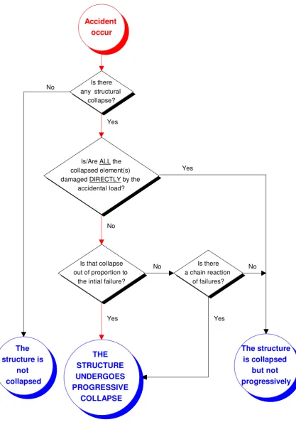
It has its own characteristics, disproportionate to initial failure and chain reaction of failures, in its failure mode. Disproportion refers to the ratio of the overall structural collapse to the initial failure rather than the ratio of the overall structural collapse to the whole structure. An additional characteristic of progressive collapse is a chain reaction of failures. The collapse of the Ronan Point apartment illustrates well this failure mode. No detailed explanation will be given. However, since the terms ‘disproportion’ and ‘chain reaction’ are subjective, it is very difficult to define disproportion numerically and to allocate certain levels of failure as chain reaction. In later of this report, some guidelines will be quoted and discussed from the Building Regulation 1985.
1.3.2 Abnormal and Accidental Loads
normal operation. ‘Abnormal load’ is defined as a loading event which has a low probability of occurrence to the structure and also is unpredictable. However, there is no certain type of load classified as accidental load or abnormal load. For example, explosive load itself could be either an accidental loading event or abnormal loading event. It all depends on the function of the bearing structure. In general, in the case of a dam structure, the probability of occurrence for an explosion would be extremely low and unlikely. Therefore, explosive load for a dam would be regarded as an abnormal load. On the contrary, in the case of a fuel station, explosion would be more probable and explosive load would, therefore, be regarded as an accidental load. In general, the probability of having an accidental event varies from structure to structure but that of an abnormal event is considered to be the same for all structures. It is example of explosive or impact of vehicle and aircraft. Accident load is same as abnormal load and defined as load event must be caused by accident occur. The probability of particular load event will be extreme low in particular structure but some structures will be higher probability. For example, fuel station is higher probability than footbridge for explosive occurrence. It is necessary to investigate the causes of progressive collapse such as abnormal and accident load. For structural design, the loading is based on possible loading events dependent on the use and nature of building or structure. According to current design codes, the characteristic load that is identified the loading possible occurs. The characteristic load multiplied by safety factor is design load. The structure will be analyzed and designed basis of design load. Nevertheless, progressive collapse will take place in case of abnormal and accident load damage key element (see paragraph 2.3).
1.3.3 Key Element
contain at least one key element. However, structures which have a redundancy greater than zero do NOT imply they have no key element(s). This can be seen from the case study.
1.3.4 Classification of Progressive Collapse
Once accident takes place and collapse occurs, most of people will think about chain reaction failure which is main factor to cause the collapse. Actually, it is not every collapse is progressive collapse. For example, a big bomb was explosive in a small building. The power of the accidental load was so great that it destroyed the whole structure of the building, and one can only say the structural collapse but not progressive collapse has occurred. The so great accidental load is very extreme case and low probability to occur. So, it is impossible to take consideration in structural design for every building.
Accident occur
Is there any structural
collapse?
Is/Are ALL the collapsed element(s) damaged DIRECTLY by the
accidental load?
Is that collapse out of proportion to
the intial failure?
Is there a chain reaction
of failures?
THE STRUCTURE UNDERGOES PROGRESSIVE
COLLAPSE The
structure is not collapsed
The structure is collapsed
but not progressively No
Yes
No
Yes
No
Yes Yes
[image:18.595.129.547.75.670.2]No
Progressive collapse should be prevented for some important buildings and civil engineering structure.
If the collapse is either ‘disproportion to its initial failure’ or ‘a chain reaction of failures’, it would regarded as progressive collapse. It had been said that these two terms were quite objective and not easy to define. However, some guidelines were given in regulation D19 of the ‘Building (Fifth Amendment) Regulations 1970’ In the paragraph 4 and the clause ‘deemed to satisfy’, ‘disproportion collapse’ was confined as the lesser of 750sq. ft. (69.68 m2) or 15% of floor area of the storey. Also, there was a confinement for ‘chain reaction of failures’ such that the failure was confined within each storey. Besides it was found that the collapse of plan floor area for Ronan Point apartment was neither greater than 69.68m2 nor over 15% of the plan floor area of the building.
2. LITERATURE REVIEW
2.1 Review of Progressive Collapse Case in U.K
Before Building Regulation 1970 (Fifth Amendment) in UK, rare document and research were related to progressive collapse. Besides, no specific requirements or standard provided to guide against progressive collapse.
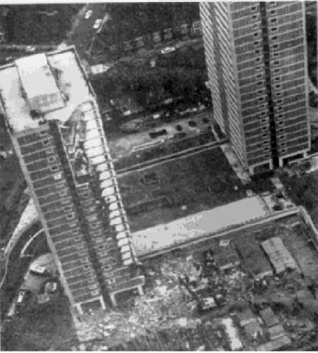
Since 1968 May, Ronan Point apartment was collapsed caused by natural gas explosion in kitchen where was in one of four corners of 23-storey pre-cast concrete building as shown in Figure 2.1. It was trigger for progressive collapse of all the corner units above and below that unit. The spectacular nature of the collapse created an enormous impact on the philosophy of structural design and resulted in important revisions of design codes. The Ronan Point report of the Court of Inquiry stated:
"It is the common aim of structural engineers so to design their structures that if one or two component parts or members fail due to any cause, the
remaining structure shall be able to provide alternative paths to resist the
loads previously borne by the failed parts." (Walters Forensic Engineering, 2007)
structure whereby a failure starting in a particular component rapidly propagates to other components precipitating a major or even a total collapse. The three most common occurrences of this type of collapse are as follows:
1. High rise concrete flat-plate structures (during construction or earthquake). 2. Formwork for concrete structures.
3. High rise structures constructed with precast concrete elements.”
Building Regulations of 1970, later developing into BS Cp 110-1972, which made it mandatory in Britain for buildings of five or more stories to be designed for the possibility of progressive collapse. This amendment applied to all structures of more than five storeys and not limited to designs using precast panels. It followed the alternate path theory and requires, in essence, that every building be designed using either of the following alternatives:
A) The designer shall ensure that the removal of any of the structural components essential to the stability of the building does not produce the total collapse of the structure and that any resulting "local" damage or collapse be restricted to the stories above and below the one at which the removal of the component was made.
B) Structural members shall not collapse if subjected to the combined dead and imposed loads acting simultaneously with a pressure of 5 psi (34.48 kPa) in any direction and any extra loads transmitted from adjacent parts of the structure subjected to this 5 psi pressure.
The need to safeguard against progressive collapse was beginning to be recognized, though not formalized in design codes, even prior to the Ronan Point collapse. The Committee European du Beton produced and published in March 1967 a comprehensive code covering the design and construction of systems buildings. This Code drew attention to the danger of progressive collapse in the following words:
"One can hardly overemphasize the absolute necessity of effectively joining
the various components of the structure together in order to obviate any
possible tendency for it to behave like a "house of cards"…"(Walters
In North America the first provisions to deal with progressive collapse were those in the BOCA (Building Officials and Code Administrators) 1981 Code. However, it was not until 1989 that the ACI - 318 Code made a first mention of the problem and not until the issuance of the 1995 Code these provisions comparable to those of BS-CP 110: 1972 were adopted.
The Canadian Standard CSA - A23.3-94 for the design of concrete structures now recognizes structural integrity as a separate limit state. The Standard includes several provisions to enhance structural integrity especially in precast and tilt-up structures, mixed or unusual structural systems and structures subjected to severe loads such as vehicle impact or chemical explosions.
The Ronan Point case stands as one of the few landmark failures that have had a sustained impact on structural thinking, an impact that affected even institutions that traditionally tend to resist change such as the ACI. (Walters Forensic Engineering, 2007)
2.2 Review of Progressive Collapse Case in U.S.A
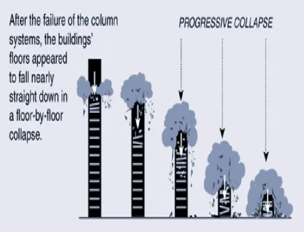
Figure 2.2 – Progressive Collapse for High Rise Building
Investigators for 911 attacks reported that progressive collapse was main factor to cause many peoples were killed. Initial collapse (local failure) caused hundreds of people were to be killed but progressive collapse caused (thousands) people to be killed. The World Trade Center tower I –WTC1 was totally collapsed within 20 minutes after the terrorist plane the building which was not enough time to escape from site for total 17400 occupants. The 911 review (2004) said:
“Progressive collapse describes a collapse in which an initiating event leads
to a disproportionate collapse. This phenomenon is rare, especially in
steel-framed buildings. The phenomenon of total progressive collapse is even
rarer. In fact, there appears to be no example of total progressive collapse of a
steel-framed building outside of the alleged examples of the Twin Towers and
Building 7.” (911 review, 2004)
The National Institute of Standard and Technology – NIST (i) was employed to investigate and find out the following issues:-
1. The procedures and practices used in the fire resistance design of structures should be enhanced by requiring an objective that uncontrolled fires result in burnout without local or progressive collapse.
_____________________________________________________________________
2. Removal of thermal expansion from the spandrels and equivalent slabs in the tenant area to avoid local buckling that affected convergence but had little influence on progressive collapse initiation
3. This further increased the gravity loads on the core columns. Once the upper building section began to move downwards, the weakened structure in the impact and fire zone was not able to absorb the tremendous energy of the falling building section and progressive collapse ensued.
4. As with WTC 1, once the upper building section began to move downwards, the weakened structure in the impact and fire zone was not able to absorb the tremendous energy of the falling building section and progressive collapse ensued.
5. The downward movement of this structural block was more than the damaged structure could resist, and progressive collapse began.
6. NIST recommends that the fire resistance of structures should be enhanced by requiring a performance objective that uncontrolled building fires result in burnout without local or progressive collapse.
weaken the steel structure and dead weight of debris from local failure. The collapse led to demands by the public to amend current building codes and provide protection against collapse caused by extreme events. Many Scientific and Engineer were researching the important issues which include assessment of load, analysis methods, and design philosophy etc.
The NIST found that design and approval of The World Trade Center were consistence with the provision of the New York City Building Code at that time. NIST found the fire rating of the floor system to vary between 3/4 hour and 2 hours; in all cases, the floors continued to support the full design load without collapse for over 2 hours. The wind loads governed the structural design of the external columns and provide the baseline capacity of the structures to withstand abnormal events such as major fires or impact damage. It significantly exceeded the requirements of the New York City Building Code. The wind load estimated by independent commercial consultants in 2002 were based on wind tunnel tests and differed by as much as 40 percent. The building codes do not require building design to consider aircraft impact. No experience with a disaster of such magnitude and any collapse of high rise building occurred so rapidly and little warning. In order to improve public safety, NIST had some recommendations as below to Public Officials and Building Owners to determine appropriate performance requirements of those tall buildings: These are especially at high risk due to their iconic status, critical function, or design.
1. Increased Structural Integrity: The structural integrity should be improved to
2. Enhanced Fire Resistance of Structure: The fire resistance should be enhanced by improving the technical basis for construction classification and standard fire resistance testing methods, use of the “structural frame” approach to fire resisting ratings. Moreover, in-service performance requirements and conformance criteria for spray-applied fire resistive materials had been developing and applying in new all building.
3. New Method for Fire Resistance Design of Structures: The Performance based
methods are alternative to prescriptive design methods. The development and evaluation of new fire resistive coating materials and technologies become a great duty for Scientist and Engineer. The objective is to enhance procedures and practices by requiring uncontrolled fires result in burnout without local or progressive collapse.
4. Improved Active Fire Protection: Any fire protection system should be enhanced
through improvement to design, performance, reliability, and redundancy of such systems such as sprinklers, standpipes/hoses, fire alarms and smoke management etc.
5. Improved Building Evacuation: The safe and rapid egress facilities can ensure
shortest time for escape and better occupant preparedness for evacuation during emergencies.
6. Improved Procedures and Practices: The design, construction, maintenance and
non-government and quasi-government entities, adoption and application of egress and sprinkler requirements in codes for existing buildings and retention and availability of building documents over the life of building.
7. Education and Training: For Fire Protection Engineer, Structural Engineer and
Architects, the professional skills of building structure and fire safety should be upgraded through professional education and vocational training. All related disciplines shall be encouraged to research the topic of safety for the structural engineering and fire engineering.
(NIST, 2002)
3.1 Early Stage of Design Methods against Progressive Collapse
Since 1968, after Ronan Point apartment underwent progressive collapse, certain circulars, general recommendations and notes were issued by the Ministry of Housing & Local Government and Institute of Structural Engineers of United Kingdom to propose amendment for Building Regulations. Finally, the Buildings Regulation (Fifth Amendment) came into force in 1970. Before 1970, the following relevant documents were issued by both the Ministry of Housing & Local Government and Institute of Structural Engineers in UK:
1. Gas Explosions in Load-bearing Brick Structures, 1970.(N.F Astbury et al.,1970)
2. Flats Constructed with Precast Concrete Panels. Appraisal and Strengthening of Existing High Blocks: Design of New Blocks
From (1) Circular 62/68, there are two basic methods to prevent from progressive collapse:
- Method A: By providing alternative paths of support to carry the load, assuming the removal of a critical section of the load-bearing walls.
In order to fulfill the requirement, the design force should be assumed to be a standard static pressure of 5 psi (34.48 kPa). It must be considered as loading case for structural design.
For the Method A above, the critical section could be referred to the key element as defined in previous section 2. The first stage of this recommendation in the design process against progressive collapse is to identify all the key elements of the structure by removing the structural elements one at a time. Once a key element is found, the second stage is to provide an alternative load path by assuming that the key element is removed. By doing so, all the key elements could theoretically be eliminated. In addition, since it is assumed that the structure is initially damaged, the design method would be regarded as Damaged Design.
progressive collapse. Since this design method against progressive collapse does not allow any structural damage, therefore, it would be regarded as a method of Undamaged Design. (Ministry of Housing & Local Government, 1968)
“In December, 1968, The Institution of Structural Engineers issued certain
general recommendations on design against progressive collapse of document
number RP/68/01 and a document which were numbered RP/68/02 (Notes for
Guidance Which May Assist in the Interpretation of Appendix 1 to Ministry of
Housing & Local Government Circular 62/68).” (RP/68/01)
Two sections which were relevant to the Method A & B mentioned above were quoted as follows:
“9 It is necessary to ensure that any local damage to a structure does not spread to other parts of the structure remote from the point of mishap and that
the overall stability is not impaired, but it may not be necessary to stiffen all
parts of the structure against local damage or collapse in the immediate
vicinity specifically requires this to be done.” (RP/68/01)
“2.5 It is not required to design individual floor or wall panels to resist an explosive force of this magnitude, but they may be so designed in order to
justify the stability of the structures under Method B.” (RP/68/02)
chain reaction of failures is not allowed, otherwise, it would be regarded as progressive collapse as classified in previous section 2. In the later parts of this recommendation, it implied the shortcoming of the Method B which recommended designing the elements of new buildings to resist the explosive load. In the second recommendation of the above, it directly pointed out that it is not required to design individual elements to resist the explosive load of magnitude 5 psi (34.48 kPa) under Method B. It implied that if the stability of the structures was designed to be justified, then local damage would be allowed. On one hand, the recommendations tried to make the Method B more practical. One the other hand, they seemed to make it tend to use the design principle of Method A. That is, Damaged Design.
Furthermore, one of the recommendations mentioned another method – ‘Venting’. It is required to provide an escape route to the outside air for the explosive pressure. Actually, door and window are weak point on the structure.
“In all room adequate ‘venting’ is required so as to provide an escape route to the outside air for the explosive pressure. This is provided, generally, by the
design of the doors and windows or by the arrangement of insubstantial
partitions leading to such doors and windows.” (RP/68/02)
“On April 1, 1970, ‘The Building (Fifth Amendment) Regulations 1970’ came into force. This amendment stems from two recommendations of the Ronan
Point Inquiry: ‘Recommendation 43: The Building Regulations should include provisions dealing with progressive collapse. Recommendation 44: A Code of
Practice applicable specifically to large concrete panel construction should be
prepared and published as a matter of urgency’(RP/68/02)
The proposed amendments which apply to recommendation 44 will not be considered further but, under recommendation 43, in addition to the requirements of the present regulation D8, which is a functional requirement concerned with the safety of buildings in respect of calculated loads, a new regulation D19 is added which applies to a building having five or more storeys (including basement storeys, if any). Briefly, a building must now be constructed in such a way that if a portion of a structural member (other than a portion satisfying certain load conditions) is removed, the consequent structural failure will be limited to an amount specified.
The important provisions are contained in paragraph 4 and 5 of Regulation D19 as follows:
“4. A building to which the provisions of this regulation apply shall be so constructed that if any portion of any one structural member (other than a
portion which satisfied the conditions specified in paragraph (5) of this
regulation) were to be removed -
(a) structural failure consequent on that removal would not occur within any
above (if any) and the storey next below (if any); and
(b) Any structural failure would be localised within each such storey.
5. The conditions referred to in paragraph (4) of this regulation are that the
portion should be capable of sustaining without structural failure the
following loads applied simultaneously:
(a) The combined dead load and imposed load;
(b) A load of 5 pounds per square inch (34.47 kN/m2) applied to that portion
from any direction; and
(c) The load, if any, which would be directly transmitted to that portion by
any immediately adjacent part of the building if that part were subjected to a
load of 5 pounds per square inch (34.47 kN/m2) applied in the same direction
as the load specified in sub-paragraph (b).” (Building Regulation in UK, 1985)
A ‘portion’ of a structural member is the lesser of either:
(a) The part between adjacent supports or between a support and the end of the member; or
(b) 2.25 times the height of the portion, which with normal storey heights is about 19 feet (5.79m).
This ‘deemed to satisfy’ clause for paragraph 4(b) is:
“If the area within which structural failure would occur would not exceed 750 sq. ft. (69.68 m2) or 15% of the area of the storey, measured in the horizontal
plane, whichever is the less’.”(Building Regulation in UK, 1985)
the ‘deemed to satisfy’ clause for paragraph 4 (b), it was trying to provide a guidance on the aspect of ‘disproportion’ and make it become more sensible.
3.2 Building Regulation in UK and British Standard Requirements
against Progressive Collapse
For disproportionate collapse from Building Regulation UK, it became approved document in Building Regulations UK 1985 as below statement:
“A3 the building shall be so constructed that in the event of an accident the structure will not be damaged to an extent disproportionate to the cause
of the damage.” (Building Regulation in UK, 1985)
This requirement was also used in provision of British Standard as below:
Clause 2.2.2.2.b – All buildings are required for effective horizontal ties such as periphery ties, internally ties to columns and walls
Clause 2.6.2.1 – Design of key element is required if the building is five or more storeys. It only means available to ensuring a structure’s integrity in normal use or capability of surviving accidents. Key elements should be designed, constructed and protected as necessary to prevent removal by accident.
Clause 2.4.3.1- Effects of exceptional loads or localized damage
If it is necessary to consider the effects of excessive loads induced by misuse or accident, the load safety factor should be taken to be 1.05 on the defined loads only to be acting simultaneously.
Clause 2.6.2.1 – Key element must be able to withstand accidental load without collapse. It is designed to be adequate stiffness to resist accidental load or protected by some measures such as bollard, defense wall etc. That key element would be known as
protected key elements.
Kingdom and Hong Kong for structural design of reinforced concrete structure. Some requirements and standard are summary as below:-
i. Progressive collapse had already been taken account into current code in building design in HK and UK.
Robustness (BS 8110-Clause 2.2.2.2 & 2.6):-
Normal method to ensure robustness provides vertical and horizontal ties which are defined as key members. Structures should be planned and designed so that they are not unreasonably susceptible to the effects of accidents. In particular, situations should be avoided from damage to small areas of the structure or failure of single elements and it may lead to collapse of major parts of the structure.
Unreasonable susceptibility to the effects of accidents may be prevented by the following precautions:-
1. All buildings are capable of safely resisting the notational horizontal design ultimate load as given in (Cl. 3.1.4.2) applied to each floor or roof level simultaneously.
2. All building are provided with effective horizontal ties (Cl 3.12.3) including around the periphery, internally and to columns and walls.
3. For the building 5 or more storeys, checking for layout is to identify any key elements failure of which would cause the collapse of more than a limited portion close to the element in question. If such elements are identified and the layout cannot be revised to avoid them, the design should take importance into account given in (Cl.2.6).
limited portion close to the element in question. It can be achieved by provision of ties in accordance with (Cl.3.12.3).
ii) For 5 or more storeys buildings, key elements should be designed incorporated the reasonable means available to ensuring a structure‘s integrity in normal use or capability of surviving accident.
Loads on key elements:-
In all cases, element and connection should be capable of withstanding a design ultimate load of 34 kPa from any direction and no partial safety factor applied. A horizontal member or part of horizontal member that lateral support vital to the stability of vertical key element, should also be key element. These loads are applied to area which will be projected area of the member.
Key elements supporting attached building components, which should be capable of supporting the reactions from any attached building components to be subject to a design ultimate loading of 34 kPa.
Design of bridging elements:-
For 5 or more storeys buildings, at each storey in turn, each vertical load bearing element is considered lost in turn. The design should be such that collapse of a significant part of structure will not occur. If catenary action is assumed, allowance should be made for the horizontal reactions necessary for equilibrium.
Ft.
Where Ft is lesser of (20 + 4 x no.) or 60 [kN] no. - The number of storeys in the structure.
3.3 Design Guideline for Civil Structure in Hong Kong about
Progressive Collapse
Highway Structure Design Manual (Highways Dept of HKSAR, 2006) stated the following requirements and standard:-
For the railway bridge, the potential loading is very large from a derailed train colliding with the substructure of a bridge crossing a railway track. It is difficult to design a support to withstand such load. Consideration shall be given to alleviating the effects of such collapse. The railway authority shall be consulted for design of bridge across or adjacent to railway tracks.
The best defense is located the support of highway and footbridge away at least 5m from the center line of nearest track. If the site condition is limited, the following precautions shall be observed:-
1. Supports shall not be pin-jointed at both top and bottom.
2. A solid plinth shall be provided around 1000 mm height above rail level with “cut-water shaped ends to deflect derailed trains.
3. If no solid plinth, the bottom of support shall be of “cut-water” shape to deflect derailed train.
be designed such that removal of one column in that group. It will not lead to the failure of the support under combination 1 load case of BS5400: Part 2. The support should be designed to withstand a nominal point load of 1000 kN in case of Highway Bridge and 500 kN in case of footbridge at 1200 mm above the rail level to ensure reasonable robustness. Railway under bridges shall be provided with ballast wall at approaches.
The design of piers of bridge over channels shall include consideration of protection against ship collision. Generally, such protection is costly, and the risk involved shall be analyzed and weighed against possibility of protecting the lives of bridge user by means.
3.4 Building Code in Australia (Australian Standard) about
Progressive Collapse
Australian Standard is document enforced by law in Australia. The Standard sets out minimum requirements for structural design and construction of concrete structure and steel structure (for example, AS3600 for concrete structure, AS4100 for steel structure, AS 1170 for loading). The following information is from the text book – Australian
Standards for Civil Engineering Student(Standard Australia, 1998)
3.4.1 Concrete Structure
serviceable, and has adequate strength while serving its intended function and
which also satisfies other relevant requirement such as robustness, ease of
construction and economy.” (Standard Australia, 1998)
Although it is not obvious to state the exact requirement against progressive collapse, the concept of robustness shall be considered in structural design for certain function intended. It is similar to British Standard. For chapter 1-Paragraph 2.8:
“Requirement such as fatigue, progressive collapse and any special performance requirements shall be considered where relevant and if
significant shall be taken into account in the design of the structure in
accordance with the principles of this Standard and appropriate engineering
principles.” (Standard Australia, 1998)
Progressive collapse is a factor in Structural Design in accordance with the principles of this Standard. For Chapter 1-Paragraph 3.1.1:
“The design of a structure for stability, strength and serviceability shall take
account of the action effects directly arising from the following loads:”
(Standard Australia, 1998)
“(e) Accidental loading, if applicable.” (Standard Australia, 1998)
Steel Structure: Chapter 2 Paragraph 3.11:
“Requirement other than those listed in Clause 3.1.2, such as differential settlement, progressive collapse and any special performance requirements,
shall be considered where relevant and, if significant, shall be taken into
account in the design of the structure in accordance with the principles of this
Standard and appropriate engineering principles.” (Standard Australia,
1998)
3.4.2 Steel Structure
It is similar to previous concrete structure. Progressive collapse shall also be considered in steel structure.
3.4.3 Design Load
Chapter 5 Paragraph 4.5:
“Braking and horizontal impact in carpark, Braking and horizontal impact
forces arising from the movement of vehicles shall be treated as additional live
loads and calculated as follows:
F=mxV2/2xdelta where F = impact or braking force, in Newtons m =gross mass of the vehicles, in kilograms
V =velocity of the vehicles, in meters per second
Delta=deceleration length, in meters” (Standard Australia,
Some design methods and recommendations are very similar. Selection of design method is dependent on the actual site conditions. The following types can be summarized from above sections:-
1. Design key element to resist any collapse.
2. Provide an escape route to the outside air for the explosive pressure. (i.e. venting)
3. Provision of protection to key elements.
4. Provision of tie with adjacent components over an area of local failure.
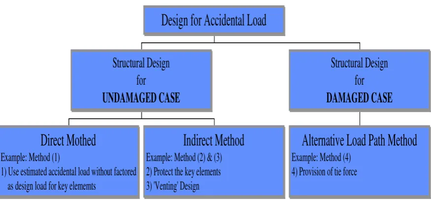
They can be classified into two main categories: - ‘Damaged Case’ and ‘Undamaged Case’ design as shown in Figure 3.1. Those are determined by key element being damaged or not. For damaged case design, key elements can be damaged or even collapsed. On the contrary, the structure must be designed all structural elements including key elements will not be damaged by accidental load for undamaged case design.
still as undamaged case design. The reason is that the weakness part which is damaged or removed by accidental load can only be a structural or non-structural element but it is NOT a key element. Besides, since ‘venting’ can reduce the explosive load such that it is not necessary to design the key element to provide adequate stiffness to resist explosive load, it is regarded as indirect method. For the design method (4), collapse of key element is allowed in case of accident, and therefore, it is classified as damaged case design. In generally, Method (4) is regarded as provision of Alternative Load Path. The principle is similar to “Jenga” game (See Figure 3.2) that means members are removed but the structure will still be stable.
Direct Mothed
Example: Method (1)1) Use estimated accidental load without factored as design load for key elememts
Indirect Method
Example: Method (2) & (3) 2) Protect the key elements 3) 'Venting' DesignStructural Design
for
UNDAMAGED CASE
Alternative Load Path Method
Example: Method (4)4) Provision of tie force
Structural Design
for
DAMAGED CASE
[image:46.595.116.554.373.576.2]Design for Accidental Load
4. COMPARISON OF DESIGN METHOD
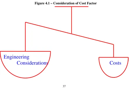
In chapter 3, many design methods were mentioned and classified various types which have their own characteristic. As a structural designer should find out the best solution against progressive collapse, we must recognize each solution for its own merits and shortcomings. Engineer judgment is important for selection of the best method based on case by case in structural designas shown in Figure 4.1. The following paragraphs will discuss about each method in details including advantages and disadvantages:-
4.1 Direct Method
It is a basic and simple method against progressive collapse directly. The accidental load must be assumed and higher than service load so much, then the structural elements would be designed to withstand the load with great protection stiffness. It will be very costly and unworthy for construction. Yet, if the accidental load in the real situation is higher than the assumption, the structure will still collapse as same as not adopting the method. The only difference is that money is wasted on strengthening the structure when adopting the direct method.
4.2 Indirect Method
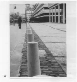
by providing ‘venting’ in case of explosion or vehicle bombing. (For example of bollard as shown in Figure 4.2)
4.3 Alternative Load Path Method
[image:49.595.101.543.506.806.2]This method is assumed a key element which is damaged by accidental load cause the original load path to be changed. It is relatively complicated because it is difficult to predict the possible damaged case. The additional cost could vary depending on the adopted solution (see Figure 4.1). However, there are always a number of solutions/schemes which can attain the provision of alternative load path. Furthermore, this method can cope with both accidental and abnormal loading event such that there would have no problem of making decision on whether what kind of accidents and how powerful of the corresponding load should be under considered as the key element is always assumed to be damaged or removed by accidental load or even abnormal load.
Figure 4.1 – Consideration of Cost Factor
Engineering
4.4
Comparison for Design Methods
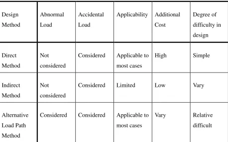
[image:50.595.110.569.370.656.2]The above design methods will be summary in Table 4.1. Direct method is the simplest but it is most costly. Indirect method (for example, bollard) as shown in Figure 4.2 is cheapest but it is the most limited application. Alternative Load Path Method (i.e. Damaged Design) depends much on the prediction of damaged case while the Direct and Indirect Method (i.e. Undamaged Design) are much more depended on the prediction of accidental event and the corresponding load.
Table 4.1 - Comparison of the Design Methods
Design Method
Abnormal Load
Accidental Load
Applicability Additional Cost
Degree of difficulty in design
Direct Method
Not
considered
Considered Applicable to most cases
High Simple
Indirect Method
Not
considered
Considered Limited Low Vary
Alternative Load Path Method
Considered Considered Applicable to most cases
Vary Relative
5. STRUCTURAL ANALYSIS FOR CASE STUDY
In previous chapter, the common design methods against progressive collapse had been mentioned and summarized in Table 4.1. It seems that direct method and alternative load path method are applicable to most cases. Alternative load path method may be economical than direct method. In order to verify the applicability of the alternative load path method, a case study of truss beam was introduced and designed by direct method and alternative load path method against progressive collapse. Selection of truss beam is because it is very simple and common in building roof and bridge structure.
For modeling, a truss beam as shown in Figure 5.1 will be assumed to be a lattice truss of 15 numbers of chord and 2 hinge supports at the both end. One of upper chord at the mid-span was assumed to be removed in damaged design as shown in Figure 5.2.
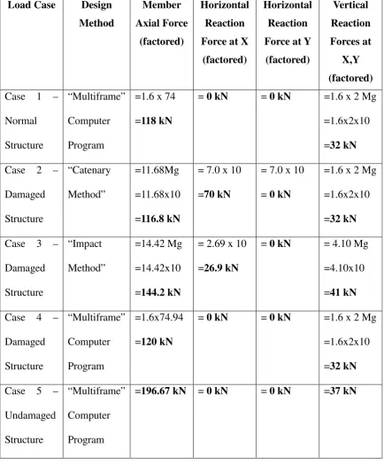
The following cases will be considered, and comparison of the result:
Case 1 – for normal design by computer program
Case 2 – for damaged design by hand calculation with “catenary method”
Case 3 - for damaged design by hand calculation with “impact method” (impact load also considered)
Case 4 - for damaged design by computer program
L/n L/n L/n L/n L/n L/n L/n L/n L/n L/n L/n L/n L/n L/n L/n
θ θ
2 4 6 8 10 12 14 16 18 20 22 24 26 28 30 32
S
1 3 5 7 9 11 13 15 17 19 21 23 25 27 29 31 33
point X point Y
L
2Mg Mg
[image:53.595.145.538.100.233.2]Mg
Figure 5.1 - Arrangement of Truss Beam
L
2
θ
Figure 5.2 - Assumed Failure Mode for Removal of an Element
Legend: d – Vertical displacement
x – Horizontal displacement.
L – Span of structure.
θ
- Angle of rotation at collapse.L
d
x X
[image:53.595.124.569.342.568.2]5.1 Geometrical Design
As shown in Figure 5.1, the pin jointed truss was arranged as a normal V-truss with
span (L) and depth (S). Two hinge supports were assumed and one will be free for
horizontal displacement. The ratio of span and depth was 10: 1. The length of each
chord was equal to L/n where n was the total number of horizontal members for the
upper chord. Each diagonal brace was formed to be angle of 2 x θ. For the loading,
impose load will be considered only owing to design for progressive collapse in this
case and dead load from self-weight will be ignored. A certain mass (M) was
pre-determined at first and it can be any weight in kg. The truss will withstand 3 point
loads – one was 2 times mass (M) at the mid-span and two were mass (M) at one quarter
of the span length of beam respectively.
5.2 Procedure for Structural Analysis
For case 1~5, design shall be based on British Standard 5950 – Structural Use of
Steelwork in Building (British Standards Institution, 1990). The point loads are
assumed to be live load and factor of safety to be 1.6 in accordance to British Standard
5950. All steel material is assumed to be grade 43 complying with British Standard
4360. Some assumptions for the structure were made as below:
1. Self-weight to be ignored when comparing with the imposed load.
2. The truss was pin-joint connected and no moment resisting.
3. The truss was simply support with vertical and horizontal restraint which
5. No moment can be transmitted at the both end support.
5.2.1 Case 1 – Normal Design for Truss Beam
Truss beam as shown in Figure 5.1 will be analyzed using computer program
“Multiframe”. In order to match computer program format, mass (M) was assumed to be
1 ton (10 kN) as input data. All node and element of the truss should be label and the
restrain conditions and supports should preset in computer program. Moreover, the
element section size will be made assumption. The results of axial load for each element
and reaction forces were come out in graphical form (for the result as shown in
Appendix B – Figure B.1~B.3). The maximum member axial force is 73.36 kN (un
factored) at middle upper chord which should be the most critical element. Member size
of 80 x 80 x 6.3 mm square hollow section is adequate as per calculation in Appendix
B.
5.2.2 Case 2 – Damaged Design for Truss Beam
Damaged truss beam as shown in Figure 5.2 using hand calculation will be analyzed
with ‘Catenary Force Method’ (Tayor and Schriever, 1976). For this design method,
alternative load path is provided by inducing of catenary force on both sides of the
supports such that on removal the member of middle upper chord. When the movement
occurs, both of supports will become horizontal restraint to catenary force (FH) to be
stable as shown in next calculation page.
Refer to following calculation sheets for solving for the maximum axial load and
Reference
5.2.2 Case 2 - Catenary Force Design
Calculation Output
Stage 1 – roller at right hand support
Stage 2 – to be hinge at right hand support during sliding stop is acting
Refer to section 5.2.2
Refer to BS5950 page 10, Table 2 for safety factor
i) Simplified analytic model for catenary force calculation
FH FH
d Fv 17 Fv
Mg Mg L/2 2Mg L/2 Damaged structure
8L/30 FH
Fv
17 Mg Free body diagram
θ
Horizontal restraint was provided at joint 16 and 18.
Owing to provision of lateral restraint at support 33, the impact force at joint 16 and 18 could be avoided.
where Fv = Vertical support
FH = Catenary force
L = length of span M = mass of loading
g = gravitational acceleration
θ = max. angle of rotation at collapse
d = max. vertical displacement
∑Fv = Summation of vertical force = 0
∑FH = Summation of horizontal force = 0
∑M = Summation of moment = 0
ii) Calculation of Catenary Force Resolving forces vertical:
Fv = 2Mg
tan(θ)=(L/30)/(L/10); θ=tan-1(1/3); θ=18.4°=>cos θ = 0.949
d = tan(θ) x L/2 x cos(θ) = tan(18.4)xL/2xcos(18.4)=0.1581L,
Taking moment at joint 17:
FH(d) - 2Mg (
L
2cosθ) + Mg (
8 30
L
cosθ) = 0
FH(0.1581L) = 0.949MgL - 0.253MgL
FH = 4.4 Mg
Apply safety factor 1.6 to imposed live loading,
Therefore, Factored (FDH) = 1.6 x 4.4 = 7.0 Mg
Fv = 2Mg
Catenary force
Reference
5.2.2 Case 2 - Catenary Force Design
Calculation Output
iii) Free body for axial force calculation
0.1L
FH=4.4Mg 1 3
N1,3
2
FV =2Mg
θ
iv) Calculation of axial force for member (1,3)
Taking moment at joint 2:
N1,3(0.1L) = FH (0.1L)cosθ + FV (0.1)sinθ
N1,3(0.1L) = 4.4Mg (0.1L)cos(18.4) + 2Mg (0.1L)sin(18.4)
N1,3 = 7.3 Mg
Apply safety factor of 1.6 to imposed live load,
therefore, FDN1,3 = 1.6 x 7.3 = 11.68Mg
Critical member
force FDN1,3
5.2.3 Case 3 – Damaged Design for Truss BeamConsideredwith Impact Force
Damaged case truss beam as shown in Figure 5.2 with hand calculation will be
analyzed with ‘Impact Design method’ (Tayor and Schriever, 1976). For this design
method, it is aimed to the analysis for the dynamic effect on the truss members when
two members hit together after removal of middle upper chord member. For stage 1, the
truss beam will be analyzed by assuming that it will collapse and attain its equilibrium
state under static load according to the damaged case as shown in Figure 5.2. The
members (14-16) and (15-17) become critical as they carry the maximum load after the
truss member (16-18) was removed. The truss beam would be collapsed. For stage 2, the
impact will be occurred at joints 16 and 18 and impact force will be added to the
damaged structure. The impact load will be calculated and then vertical and horizontal
forces at supports can also be calculated. Following assumptions were made as below:
1. At collapse, support Y can provide no frictional or horizontal resistance but
vertical resistance only.
2. ω is the angular velocity of the masses immediately before impact of joint 16
and 18.
Refer to the following calculation sheets for solving for the maximum axial load and
Reference
5.2.3 Case 3 - Impact Design: Detail Calculation
Calculation Output
Stage 1: Calculation of support and axial forces for equilibrium state
(i) Analytic Model
fhs
X
Y
θ
fvs
Mg
2Mg fvs
Mg
1 33
18 16
9 25
19 17
where
fvs = vertical support reaction when in equilibrium state
fhs = horizontal support reaction when in equilibrium state
(ii) Calculation of vertical and horizontal supports
Resolving forces vertically:
2fvs = (M + 2M + M)g
∴ fvs = 2Mg
Taking moment about joint 17:
=> fhs = 0
fvs = 2 Mg
Reference
5.2.3 Case 3 - Impact Design: Detail Calculation
Calculation Output
Refer to
section 6.1
θ = 18.4°
=>cosθ = 0.949
(iii) Calculation of axial force for member (15,17)
Free Body:
2
fvs =2Mg
16
15 N15,17
θ
θ
Mg
Taking moment about joint 16:
f
(
15L
30
cos
Mg
8L
30
cos
N
vs
[
)
θ
]
=
(
)
θ
+
15,17( .
01L
)
2Mg(15L
30 Mg
8L
30 N
N Mg
15,17
15,17
)( . ) ( )( . ) ( . )
.
0 949 0 949 01
6 96
= +
⇒ =
L
Apply safety factor 1.6 on imposed load, then
FDN15,17 = 11.14Mg
Reference
5.2.3 Case 3 - Impact Design: Detail Calculation
Calculation Output
Refer to
section 6.1
θ = 18.4°
=>cosθ = 0.949
(iv) Calculation of axial force for member (14,16)
Free Body:
N14,16
Mg 2
fvs=2Mg
14
13
θ
θ 15
Taking moment about joint 15:
f (13L
30 cos N Mg
6L
30 cos
vs ) θ+ 14,16( .01L)= ( ) θ
2Mg(13L
30 N Mg
6L 30
N Mg
14,16
14,16
)( . ) ( . ) ( )( . )
.
0 949 01 0 949
6 67
+ =
⇒ = −
L
Apply safety factor 1.6 on imposed load, then
FDN14,16 = -10.67Mg
Reference
5.2.3 Case 3 - Impact Design: Detail Calculation
Calculation Output
Stage 2: Calculation of supports and axial force for Impact
(A) Calculation of Impact load of joint 16 on 18
(i) Simplified Analytic Model
fhd
0.1L X
Y
2Mg Mg
Mg
L/4 L/4
L/4 L/4
fvd
fvd
17 18 16
θ
Where L : length of span
M : mass of loading
Reference
5.2.3 Case 3 - Impact Design: Detail Calculation
Calculation Output
(ii) Immediately before impact of joints 16 on 18
Free Body:
ω 1
fhd
fvd
16
17 T
9
θ
Mg
θ Mg
θ
L/4 L/4
θ
where
fhd : Horizontal component at support for circular motion
fvd : Vertical component at support for circular motion
T : Centrifugal force of masses
ω : Angular velocity
For equilibrium:
T - Mgsin - Mgsin = M(L
4 M(
L 2
2 2
θ θ )ω + )ω
Energy Eqn:
kinetic energy = potential energy 1
2M(
L
4 +
1
2M(
L
2 = Mg(
L
4 sin Mg(
L
2 sin
2 2
)2ω )2ω ) θ+ ) θ
eqn(1)
Reference
5.2.3 Case 3 - Impact Design: Detail Calculation
Calculation Output
Refer to section 5.2.2
θ = 18.4°
From eqn(1),
( 4 )(
3L T - 2Mgsin ) = M
2
θ ω
From eqn(2),
Mω2= 24
5LMgsinθ
Sub eqn(3) into (4), we have
3
4L(T 2Mgsin ) =
24
5LMg
T =28
5 Mg
T = 1.77Mg
− θ θ
θ
sin
sin
Vertically
Therefore, fvd = Tsinθ
fvd =
28
5 Mgsin
2θ
fvd = 0.56Mg
Fv = fvsc + fvd
= 2Mg + 0.56Mg
Fv = 2.56Mg
Apply safety factor 1.6 on imposed load, then
FDV = 4.10 Mg
eqn(3)
eqn(4)
T = 1.77Mg
fvd =0.56Mg
FDV =
Reference
5.2.3 Case 3 - Impact Design: Detail Calculation
Calculation Output
Axial force
for N16,17
= -7.33Mg
Horizontally,
fhd = Tcosθ
=
14
5 Mgsin2θ
fhd = 1.68Mg
FH = fhs + fhd
=0+
14
5 Mgsin2θ
FH = 1.68Mg
Apply safety factor 1.6 on imposed load, then
FDH = 2.69 Mg
ω
FHD
RD
1
fvd
16
17 T
9
θ
Mg
θ Mg
θ
L/4 L/4
θ
Resolving the forces of the free body horizontally:
RD = FHD =
14
5 Mgsin2θ
RD = 1.68Mg
Impact load of joint 16 on 18 (R) = RD + N16,18
R = (-1.68-7.33)Mg
R =9.01Mg in compression
Apply safety factor 1.6 on imposed load, then
FDR = 14.42 Mg
fhd =1.68Mg
FDH =
2.69Mg
RD =1.68Mg
FDR =
14.42 Mg
Member size 90 x 90 x 5 mm square hollow section is adequate as per calculation in
5.2.4 Case 4 – Damaged Design for Truss Beam with Computer Program
Damage case truss beam as shown in Figure 5.2 using computer program “Multiframe”
will be analyzed. The procedure and loading are same as case 1 but the middle upper
chord member is deleted and the collapse shape as shown in Figure 5.2. The results are
shown in Appendix B, Figure B4~B7. The maximum member axial force is 74.94 kN
(un-factored) at the lower chord at mid-span. Member size 80 x 80 x 6.3 mm square
hollow section is also adequate as per calculation in Appendix B. The result is slightly
higher than case 1 owing to induced additional force by collapse shape.
5.2.5 Case 5 – Undamaged Design by Direct Method for Truss Beam with
Computer Program
Undamaged case of truss beam as shown in Figure 5.1 using computer program
“Multiframe” will be analyzed. The procedure is same as case 1 but the