This is a repository copy of
A low-loss reconfigurable frequency selective surface based
antenna for direct antenna modulation
.
White Rose Research Online URL for this paper:
http://eprints.whiterose.ac.uk/131947/
Version: Accepted Version
Proceedings Paper:
Henthorn, S.D., Ford, K.L. orcid.org/0000-0002-1080-6193 and O'Farrell, T. (2018) A
low-loss reconfigurable frequency selective surface based antenna for direct antenna
modulation. In: Antennas & Propagation Conference (LAPC 2017), Loughborough.
Antennas & Propagation Conference (LAPC 2017), Loughborough, 13-14 Nov 2017,
Loughborough, UK. IET . ISBN 978-1-78561-700-3
https://doi.org/10.1049/cp.2017.0233
[email protected] https://eprints.whiterose.ac.uk/
Reuse
Items deposited in White Rose Research Online are protected by copyright, with all rights reserved unless indicated otherwise. They may be downloaded and/or printed for private study, or other acts as permitted by national copyright laws. The publisher or other rights holders may allow further reproduction and re-use of the full text version. This is indicated by the licence information on the White Rose Research Online record for the item.
Takedown
If you consider content in White Rose Research Online to be in breach of UK law, please notify us by
antenna for Direct Antenna Modulation
Stephen Henthorn, Kenneth Lee Ford, Timothy O’Farrell
Dept. of Electronic and Electrical Engineering, University of Sheffield, Sheffield, United Kingdom, [email protected]
Keywords: Frequency selective surfaces, Direct antenna modulation, Phase shift keying, reconfigurable antennas
Abstract
A directly modulating antenna incorporating a reconfigurable Frequency Selective Surface (FSS) for arbitrary phase mod-ulation is designed and simulated. A 4-layer FSS is used to minimise constellation distortion, with only 1.5dB variation in transmitted magnitude for 360ophase change. Low loss
sub-strates and Barium Strontium Titante (BST) variable capacitors are simulated to reduce the antenna loss to 1.3dB in the filter pass band and achieve an average total efficiency of 65% when producing an 8-PSK constellation.
1
Introduction
Modern communications systems make use of complex digital modulation schemes, producing waveforms which are broad-band and often have significant peak to average power ratios (PAPRs). In conventional transmitters, this places a require-ment on the power amplifier (PA) to be linear across the input power and frequency ranges in order to avoid distorting the sig-nal [1]. This often results in the PA being operated at back-off from its saturation point, reducing the power efficiency signifi-cantly. Recently, considerable effort has been made to improve efficiency and reduce distortion, including PA designs such as the Doherty amplifier [2], and predistortion of the signal [3], both of which add complexity to the transmitter.
[image:2.595.312.542.221.262.2]A recent approach to the problem is Direct Antenna Modula-tion (DAM), where an amplified carrier wave is modulated at the antenna. This means only the carrier wave is amplified, rather than the broadband modulated waveform, allowing the PA to operate in its efficient non-linear region without adding distortion. Several approaches have been taken, including inte-grating active components into the antenna to produce simple modulation schemes [4], or surrounding the antenna by passive switched reflectors to produce directional complex modulation [5]. We recently, [6], proposed an antenna loaded with a three-layer reconfigurable Frequency Selective Surface (FSS), using varactor diodes to vary the FSS centre frequency, and hence the transmitted phase from the antenna (Fig. 1). Its performance as a modulator is evaluated in an end-to-end Quadrature Phase Shift Keying (QPSK) communications system in [7].
Fig. 1:Concept of a DAM modulator using an FSS
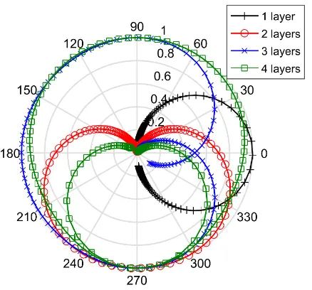
Fig. 2:Polar plot of transmitted signal of LC bandpass filters of different orders with changing capacitance
This paper further develops the work of [7], presenting an DAM for QPSK, continuous phase and polyphase signals [8]. The design uses low-loss materials and devices to improve the antenna efficiency, and a 4-layer FSS for an improved modula-tion performance. The antenna design and its performance as an antenna and a modulator are discussed.
2
Frequency Selective Surface design
[image:2.595.320.539.296.500.2]Fig. 3:FSS unit cell design
1 1.5 2 2.5
Frequency (GHz) -40
-35 -30 -25 -20 -15 -10 -5 0
Magnitude (dB) S11, 0.6pF S11, 1pF S11, 1.4pF S21, 0.6pF S21, 1pF S21,1.4pF
Fig. 4:Reflection and transmission coefficients of FSS design in free space
The 4 layer design was selected as it provides a maximum of less than 1dB variation around the whole constellation, and in a real system there is a trade-off with loss increasing linearly with the number of layers.
A square-loop aperture design for the FSS was chosen for its stability with angle of incidence, its relatively broadband fre-quency response and its ease of implementation. The unit cell geometry was designed using the square-loop design equations in [9] and Babinet’s principle. In order for the FSS to resonate at 1.8GHz when variable capacitors are integrated, the geome-try was designed for 3.4GHz. The design in Fig. 3, produces an equivalent inductance and capacitance of 24pH and 93pF, respectively.
The design was validated in CST Microwave Studio, using Floquet boundaries in free space to simulate four infinite FSS spaced byλ0/4. The unit cell geometry was simulated as PEC, and each layer had a 1.6mm TLY5 fibreglass sub-strate, chosen for its low loss tangent at microwave frequen-cies (ǫr2.2, tanδ = 0.0009). Variable capacitors were
inte-grated across the gaps in the unit cell to allow tuning of the
(a)
(b) (c)
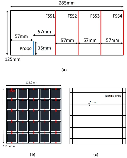
Fig. 5:(a) Side-on view of final antenna design, (b) Front-on view of antenna design, (c) Reverse of each FSS layer
FSS to produce modulation. STPTIC-27G2 variable capaci-tors, which are based on a Barium Strontium Titanate mate-rial, were chosen for their high Q-factor at the frequency of interest and good linearity [10]. The capacitors were simu-lated as lumped elements with a tuning range of0.6 to3pF and an Equivalent Series Resistance (ESR) of0.6Ω. However, only the lower half of the capacitance range is explored, as increasing C increases the current through the variable capac-itor, leading to higher resistive losses in the component. This is marginally offset by a lower ESR for a similar Q-factor at larger capacitances, but losses through the surfaces were found to still increase. The simulation shows between 1.1dB and 0.3dB minimum transmission loss at various capacitances (Fig. 4).
3
DAM Antenna design
[image:3.595.56.276.153.437.2]0.9 1 1.1 1.2 1.3 1.4 1.5
Capacitance (pF)
-20 -15 -10 -5
Normalised farfield at boresight (dB)
(a)
0.9 1 1.1 1.2 1.3 1.4 1.5
Capacitance (pF) 0
50 100 150 200 250 300 350
Farfield phase at boresight (Degrees)
[image:4.595.65.268.73.439.2](b)
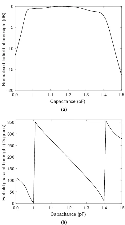
Fig. 6:(a) Magnitude and (b) phase variation of E-field at boresight in the farfield with varying capacitance
derived guide quarter-wavelength,λg/4 = 76mm, also does
not produce an optimal filter. Simulation in CST found that a spacing of λs/4 = 57mm gives an optimally flat filter
re-sponse at 1.8GHz. The capacitors are modelled as before, and are placed in alignment with the antenna E-field to minimise the number of components required. 1mm wide bias lines are modelled on the reverse of the FSS substrate, and are mostly orthogonal to the cavity E-field, with the two vertical lines to-ward the edges of the antenna to minimise their effect on the transmitted signal, as shown in Fig. 5c.
4
Antenna performance
The full antenna was simulated in CST Microwave Studio. Fig.6 shows the boresight normalised farfield magnitude and phase received at 1.8GHz with changing capacitance. It shows a nearly flat magnitude response between 0.97 and 1.39pF, with a highly linear phase change in this region. Between 0.97 and 1.38pF, there is360◦of phase change for only 1.5dB vari-ation in magnitude, giving the maximum difference in magni-tude between two arbitrary PSK constellation points.
0.9 1 1.1 1.2 1.3 1.4 1.5
Capacitance (pF) 0
20 40 60
[image:4.595.327.527.77.248.2]Total efficiency (%)
Fig. 7:Total simulated efficiency of antenna with varying ca-pacitance
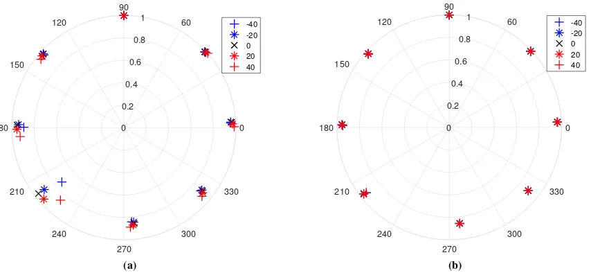
The total efficiency of the antenna is simulated as varying be-tween 54.5% and 73% in the filter pass region, with a mean of 65% (Fig. 7). Losses occur in the substrate and the para-sitic resistance of the variable capacitors. However, at 0.98pF, there is a decrease in antenna efficiency but an increase in the magnitude of the signal received at boresight. This is due to an increase in peak directivity at this point. As such, the con-stellation in directions other than boresight must be considered when selecting constellation patterns, as reflected non-Line-of-Sight (LoS) paths with a distorted constellation may inter-fere in a less determinate way with a boresight constellation at a receiver. Fig. 8 shows an 8-PSK constellation at vari-ous observation angles within the maximum 3dB beamwidth, 80◦, in both E- and H-planes, where each complete constella-tion is normalised. The constellaconstella-tion is completely stable in the H-plane, and the different points have only 14% variation in absolute amplitude. In the E-plane, there is more variation, with up to 26% difference in amplitude and11◦in phase at a viewing angle of40◦. However, this constellation is transmit-ted with 3dB less power than the boresight constellation, so any interference from reflected impaired constellations should be small.
5
Conclusion
A directly phase modulating antenna incorporating a reconfig-urable FSS has been designed and simulated. The design is simulated as able to produce an 8-PSK constellation with only 14% variation in constellation magnitude. The antenna loss is 1.3dB in the filter pass band and achieves an average total efficiency of 65% across an 8-PSK constellation.
Acknowledgements
0 30 60 90
120
150
180
210
240
270
300 330 0
0.2 0.4
0.6 0.8
1
-40 -20 0 20 40
(a)
0 30 60 90
120
150
180
210
240
270
300 330 0
0.2 0.4
0.6 0.8
1
-40 -20 0 20 40
[image:5.595.85.512.89.286.2](b)
Fig. 8:Simulated 8-PSK constellation from antenna at various observation angles in (a) E-plane (b) H-plane
References
[1] Raghavan, A., Srirattana, N., Laskar, J.: “Modeling and Design Techniques for RF Power Amplifiers”, (Wiley-IEEE Press, 2008)
[2] Raghavan, A., Srirattana, N., Laskar, J.: “Efficiency En-hancement of RF Power Amplifiers”, in ‘Modeling and Design Techniques for RF Power Amplifiers’ (Wiley-IEEE Press, 2008), pp 173–198.
[3] Lei, D., Zhou, G. T., Morgan, D. R., Ma Zhengxiang, Kenney, J. S., Jaehyeong, K., Giardina, C. R. “A robust digital baseband predistorter constructed using memory polynomials”, IEEE Transactions on Communications,
52,pp. 159-165, (2004).
[4] Daehee, P., Minhoe, K., Dong-Ho, C. “Novel single-RF MIMO system based on repetitive Pulse Width Modula-tion”, IEEE Communications Letters,20,pp. 165–168, (2016).
[5] Babakhani, A., Rutledge, D. B., Hajimiri, A. “Trans-mitter architectures based on near-field Direct Antenna Modulation”, IEEE Journal of Solid-State Circuits,43,
2674–2692, (2008).
2017 11th European Conference on Antennas and Prop-agation (EUCAP), Paris, France, 2017, pp. 731-734.
[6] Henthorn, S., Ford, K. L., O’Farrell, T. “Frequency Se-lective Surface loaded antenna for Direct Antenna Mod-ulation”, 2017 11th European Conference on Antennas and Propagation (EUCAP), Paris, France, (2017), pp. 731-734.
[7] Henthorn, S., Ford, K. L., O’Farrell, T. “Bit error rate performance of quadrature modulation transmission us-ing reconfigurable Frequency Selective Surfaces”,IEEE
Antennas and Wireless Propagation Letters,PP(99), pp. 1–1, (2017).
[8] O’Farrell, T. “New signature code sequence design techniques for CDMA systems”, Electronics Letters,
27, pp. 371–373, (1991).
[9] Langley, R. J., Parker, E. A. “Equivalent circuit model for arrays of square loops”, Electronics Letters,18, pp. 294–296, (1982).
[10] STMicroelectronics. “STPTIC-27G2
Parascan tunable integrated capacitor”,