This is a repository copy of
Tuneable Dual-band Antenna for Sub 1 GHz Cellular Mobile
Radio Applications
.
White Rose Research Online URL for this paper:
http://eprints.whiterose.ac.uk/104358/
Version: Accepted Version
Proceedings Paper:
Bai, Q., Singh, R., Ford, K. et al. (2 more authors) (2017) Tuneable Dual-band Antenna for
Sub 1 GHz Cellular Mobile Radio Applications. In: 2016 Loughborough Antennas &
Propagation Conference (LAPC). 2016 Loughborough Antennas and Propagation
Conference, 14 - 15 November 2016, Loughborough, UK. IEEE . ISBN 978-1-5090-0783-7
https://doi.org/10.1109/LAPC.2016.7807556
© 2016 IEEE. Personal use of this material is permitted. Permission from IEEE must be
obtained for all other users, including reprinting/ republishing this material for advertising or
promotional purposes, creating new collective works for resale or redistribution to servers
or lists, or reuse of any copyrighted components of this work in other works.
eprints@whiterose.ac.uk https://eprints.whiterose.ac.uk/
Reuse
Unless indicated otherwise, fulltext items are protected by copyright with all rights reserved. The copyright exception in section 29 of the Copyright, Designs and Patents Act 1988 allows the making of a single copy solely for the purpose of non-commercial research or private study within the limits of fair dealing. The publisher or other rights-holder may allow further reproduction and re-use of this version - refer to the White Rose Research Online record for this item. Where records identify the publisher as the copyright holder, users can verify any specific terms of use on the publisher’s website.
Takedown
If you consider content in White Rose Research Online to be in breach of UK law, please notify us by
Tuneable Dual band Antenna for Sub 1 GHz Cellular
Mobile Radio Applications
Q. Bai, R. Singh, K. L. Ford, R. J. Langley, and T. O’Farrell
Department of Electronic & Electrical Engineering,The University of Sheffield, S1 3JD, UK
Email: {q.bai, r.singh, l.ford, r.j.langley, t.ofarrell }@sheffield.ac.uk
!
" #
$ % &
'%% # (%) $ )* #
# #
# +$
I. INTRODUCTION
Recently, multi band tuneable antennas have attracted considerable attention due to the developing demand on dynamic spectrum usage and carrier aggregation (CA) in forthcoming wireless communication systems [1]. To achieve frequency agility and concurrent multi band operation, systems may require that the antenna supports multiple frequency bands simultaneously with each band independently tuneable. Moreover, the antenna needs to be compact in volume to fit in modern user equipment (UE), such as mobile handset and tablet [2][3].
Various antenna types have been reported for dual band tuneable antenna design. In [4], a dual band planar inverted F antenna (PIFA) was presented to cover the frequency range from 0.7 to 1.1 GHz and from 1.7 to 2.3 GHz for LTE carrier aggregation. A tuneable L shape patch antenna was investigated in [5] for GSM/DSC 1800 applications. In [6], a folded slot antenna was proposed to provide two band coverage over a wide tuning range from 1 to 3 GHz. However, the independent tunability was not fully addressed in previous tuneable dual band antenna designs with single feeding structure, which means tuning one band may shift the resonant frequency of the other band. The isolation between two tuneable frequency bands can be improved by using a dual feeding structure [4] or by employing a feeding network [7], which will increase the complexity of the antenna geometry.
The slot antenna has been used in many tuneable antenna designs due to its simple structure with flexible matching performance. Furthermore, it can be easily embedded in the PCB ground plane, and accommodate nearby electronic components [6][8][9][10]. In this paper, a single feed tuneable dual band slot antenna will be presented. The position of slot
elements and the locations of the tuneable capacitors and feeding points are carefully selected to make two resonant frequency bands independently tuneable. This antenna is designed to cover the frequency range from 560 MHz to 1 GHz for carrier aggregation between the TV white spaces (TVWSs) or unused digital terrestrial television (DTT) bands and sub GHz LTE bands. The antenna performance will be evaluated for high order QAM formats using our hardware in the loop concurrent dual band test bed to investigate the inter band interference between the concurrent independent transmissions, which can significantly deteriorate the overall system performance [11].
II. ANTENNA STRUCTURE
The antenna is designed on a 100 × 40 × 1.6 mm3 double
side coated printed circuit board (PCB) with the dielectric constant of 4.3 and loss tangent of 0.025. As shown in Fig. 1, the antenna consists of two open end slots, which are placed perpendicularly to each other to reduce the mutual coupling. The longer slot is 32 × 2 mm2 and placed in parallel with the
short edges of the PCB. The second slot is 26 × 2 mm2, placed
perpendicularly to the longer slot with 2 mm separation. Two slots are driven by a 50 ohm stripline printed on the back side of the PCB. The longer and shorter slots are adjusted to be resonant at the lower and higher frequencies respectively, and to provide two concurrent operating frequency bands. Two varactors, one on each slot, are used to tune two resonant frequencies separately.
[image:2.595.365.504.538.693.2]Fig. 2. Fabricated antenna with baising network
Fig. 2 shows the top and bottom views of the fabricated antenna. Bias networks are integrated in order to tune two varactors [12], which have a capacitance tuning range from 0.6 pF to 10 pF with a maximum bias voltage of 30 V. The microstrip feeding line is extended to the centre of the PCB to minimize the interference from the SMA connector and coaxial cable during the measurement.
III. RESULTS AND DISCUSSION
The main challenge of this dual band tuneable antenna design is to achieve the independent tunability within a very limited PCB space. In other words, each resonant frequency needs to be tuned individually without affecting the other band.
Fig. 3 (a) and (b) present the simulated surface current distributions of the proposed antenna when it is operating at 0.6 GHz and 1 GHz, respectively. It is clear to see that the 32 mm slot is mainly radiating at 0.6 GHz whereas the 26 mm slot is working at 1 GHz. A good isolation has been obtained between two slots, which indicates two operating bands may be tuned independently.
(a) (b)
Fig. 3. Surface currents distribution at (a) 0.6 GHz, (b) 1 GHz
The measured antenna reflection coefficients under various biasing voltages are plotted in Fig. 4 (a) and (b). The higher band 6 dB tuning range covers from 800 MHz to 1.14 GHz (Fig. 4a). Importantly, the lower band resonance are almost unaffected by the higher band tuning. It is also observed in the
measurement that the minimum separation between two bands of this antenna is about 100 MHz, which means one band will start being shifted when the other band is closer than 100 MHz. The antenna lower band can be tuned from 560 MHz to 800 MHz (Fig. 4b). It is noticed that the higher band matching performance can be affected during the lower band tuning, but the resonant frequency and 6 dB bandwidth remain the same. More details of the capacitance value and the corresponding resonant frequency and bandwidth are listed in TABLE I.
(a)
(b)
[image:3.595.44.282.53.212.2]Fig. 4. Measured antenna reflection coefficeint: (a) tuning varactor C2, (b) tuning varactor C1.
TABLE I ANTENNA TUNING TABLE
,!
,-Capacitance
(pF) 4.2 3.3 2.5 1.5 5.2 1.8 1.4 0.8 Resonant
Frequency (MHz)
543 593 650 781 792 907 993 1050
6 dB Bandwidth
(MHz)
[image:3.595.305.558.165.550.2] [image:3.595.39.289.499.627.2] [image:3.595.307.560.600.716.2]Fig. 5 (a) and (b) show the measured antenna radiation pattern E and H plane cut at 0.6 and 1 GHz, respectively. The antenna radiation appears omni directional at 0.6 GHz with measured gain of 1.7 dBi. At 1 GHz, a null is noticed at 122º on the E plane cut. The measured gain at 1 GHz is 3.9 dBi. The antenna gain can be further improved by using low loss substrate materials and low ESR tuneable capacitors, which will be considered in the next stage of this research.
(a)
(b)
Fig. 5. Measured radiation pattern (normalized) at (a) 600 MHz, (b) 1 GHz
By utilising the dual band antenna, a concurrent dual band test bed system can be realised as shown in Fig. 6. The controller (PXIe 8135) [13] is essentially a PC running LabVIEW and MATLAB software packages. The baseband signal processing takes place in the controller, where two different baseband I/Q signals are generated in LabVIEW and sent to the dedicated reconfigurable RF signal generators (PXIe 5793) [14] operating at different carrier frequencies. The RF outputs of the signal generators are combined by a ZAPD 2 272 S+ combiner [15] and the combined signal is transmitted through a wideband antenna (UHALP 9108 A) [16]. At the receiver side, the newly designed dual band antenna detects the mixed signal, which is directly digitised through an oscilloscope [17]. Then the mixed signals are converted to baseband through digital down conversion (DDC), and separated through cascaded integrated comb (CIC) decimation
filters back at the controller unit. After which the baseband demodulation takes place.
[image:4.595.307.561.86.162.2]Fig. 6. The dual band test bed system schematic.
TABLE II CONSIDERED LTE AND DTT BAND COMBINATIONS FOR EVALUATION OF DUAL BAND SYSTEM
, . , /
0 1
2
. # 0 1
DTT 50 and DTT 49 706 and 697 12 (6+6)
LTE 20 and DTT 49+50 796 and 702 20 (10+5+5)
LTE 20 and DTT 43 796 and 650 16 (10+6)
In order to investigate the frequency agility and concurrent multiband transmission capability, various TVWSs (in Sheffield city UK) and sub GHz LTE bands were used, and 16 QAM and 64 QAM single carrier signals, with root raise cosine filtering at a roll off (β) of 0.5, were analysed in CA mode over the dual band system. The considered bands in CA mode are provided in Table II, together with band centre frequencies and aggregate bandwidths. It can be noticed from the centre frequencies shown in Table II that the band combinations were chosen such that the frequency separation between the concurrent bands changes from a few MHz to hundreds of MHz. This allowed the investigation of inter band interference over the concurrent dual band system.
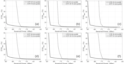
Fig. 7 shows the EVM performance of the considered concurrent single carrier transmissions in CA mode over a scale of received power from 60 to 85 dBm. Fig. 7(a), 7(b) and 7(c) shows the EVM performance when DTT band 49 and LTE band 20 use 16 QAM modulation, while 64 QAM modulation is used over DDT band 50, DTT bands 49 & 50 (combined) and DTT band 43. On the other hand, figures 7(d), 7(e) and 7(e) show the considered bands when the modulation ordered are swapped between the concurrent bands. DTT bands 49 and 50 were used as two separate concurrent bands for the results shown in Fig. 7(a) and 7(d). However, given the two bands are adjacent, they can also be used as one wide band as shown in Fig. 7(b) and 7(e).
[image:4.595.77.247.148.487.2] [image:4.595.309.557.224.297.2]TABLE III DIFFERENCE IN RECEIVED POWER (%) BETWEEN THE CA AND SINGLE BAND TRANSMISSION MODES, FOR EACH CONSIDERED
BAND AT DIFFERENT EVMRMS (%).
.
' 3 4 # 051
LTE 20 (16 QAM) 0.6098 0.2398 0 0.3571 LTE 20 (64 QAM) 0.1342 0.1328 0.6623 0.6596 DTT 43 (16 QAM) 1.0976 0.2389 0.5924 0.4728 DTT 43 (64 QAM) 0.4000 0.3979 0.3963 0.5263 DTT 49 (16 QAM) 0.2433 0.8333 0.3550 0.3542 DTT 49 (64 QAM) 0.6623 0.7884 0.9126 0.9103 DTT 50 (16 QAM) 1.4423 0.3584 0.3571 0.1185 DTT 50 (64 QAM) 0.9296 0.3947 0.6527 0.6510
In order to investigate the inter band interference between the concurrent bands, experiments without the use of CA were also carried out. In this case, the 16 QAM and 64 QAM signals were analysed independently over each of the considered bands and the EVM results are shown in Fig.8. These results show that the EVM performance in independent signal transmission is also almost identical to that seen in the CA case (in Fig. 7). Table III compares the received power difference on dB scale, for a certain EVMrms, in the CA and single band transmission
modes, for the eight different bands considered in this investigation. Table III shows that for four different EVMrms,
the difference in received power in the two different modes of transmission does not exceed 1.5% across the eight different bands and that the average power difference is approximately 0.5% over all the bands. This shows that the analogue filtering
[image:5.595.45.549.62.323.2]at the dual band tuneable antenna and the digital filtering after the DDC effectively avoid any harmful interference between the concurrent bands, especially in the case where the band separation in frequency is small.
Fig. 8. EVMrms (%) evaluation of independent 16 QAM and 64 QAM
transmissions over the dual band system for the considered LTE and DTT bands.
IV. CONCLUSIONS
This paper presents a compact tuneable dual band antenna designed for sub GHz cellular band applications. The results show that the antenna frequency tuning range is able to cover from 560 MHz to 1.1 GHz with two concurrent but independently tuneable operating bands. The antenna was also tested in a concurrent dual band test bed system for carrier aggregation between LTE and DTT bands, where the EVM performance results in CA and single band transmission modes Fig. 7. EVMrms (%) evaluation of concurrent 16 QAM and 64 QAM single carrier transmissions over a dual band system utilising the dual band antenna
[image:5.595.51.276.399.532.2] [image:5.595.336.528.411.557.2]show significant agreement. The difference in received power between the CA and single band transmission modes is approximately 0.5% for a certain EVM value, which shows that there is significant isolation between the concurrent transmissions in the CA mode, even in case of very small frequency separation between the two bands.
ACKNOWLEDGMENT
This work is funded by the UK government under the EPSRC /232' grant (EP/M013723/1).
REFERENCES
[1] Evolved Universal Terrestrial Radio Access, “Further advancements for E UTRA physical layer aspects,” 3GPP TR 36.814, Tech. Rep., 2010. [2] J. Ilvonen, R. Valkonen, J. Holopainen and V. Viikari, "Design Strategy
for 4G Handset Antennas and a Multiband Hybrid Antenna," in
! " , vol. 62, no. 4, pp. 1918 k1927, April 2014.
[3] K. L. Wong and C. Y. Tsai, "Low Profile Dual Wideband Inverted T Open Slot Antenna for the LTE/WWAN Tablet Computer With a Metallic Frame," in ! " , vol. 63, no. 7, pp. 2879 2886, July 2015.
[4] B. Avser and G. M. Rebeiz, "Tunable Dual Band Antennas for 0.7–1.1 GHz and 1.7–2.3 GHz Carrier Aggregation Systems," in
! " , vol. 63, no. 4, pp. 1498 1504, April 2015.
[5] A. F. Sheta and M. A. Alkanhal, "Compact dual band tunable microstrip antenna for GSM/DCS 1800 applications," in # $
% ! " , vol. 2, no. 3, pp. 274 280, April 2008.
[6] N. Behdad and K. Sarabandi, "Dual band reconfigurable antenna with a very wide tunability range," in
! " , vol. 54, no. 2, pp. 409 416, Feb. 2006.
[7] A. Boukarkar, X. Q. Lin and Y. Jiang, "A Dual Band Frequency Tunable Magnetic Dipole Antenna for WiMAX/WLAN Applications,"
in & ! " ' , vol. 15, pp. 492
495, 2016.
[8] D. Peroulis, K. Sarabandi and L. P. B. Katehi, "Design of reconfigurable slot antennas," in ! " , vol. 53, no. 2, pp. 645 654, Feb. 2005.
[9] K. L. Wong and C. Y. Tsai, "Low Profile Dual Wideband Inverted T Open Slot Antenna for the LTE/WWAN Tablet Computer With a Metallic Frame," in ! " , vol. 63, no. 7, pp. 2879 2886, July 2015.
[10] K. L. Wong and P. W. Lin, “Integration of monopole slot and monopole strip for internal WWAN handset antenna,” Microw. Opt. Technol. Lett., vol. 54, pp. 1718–1723, 2012.
[11] L. E. Aguado, K. K. Wong and T. O'Farrell, "Coexistence issues for 2.4 GHz OFDM WLANs," () * + , " $
, + - .+ - * / 0123, 2002, pp. 400
404.
[12] Infineon, “Silicon Tuning Diodes, BB833 E6327.” [Online]. Available: http://www.farnell.com/datasheets/1835975.pdf
[13] National Instruments, “Embedded Controller, PXIe 8135.” [Online]. Available: http://www.ni.com/datasheet/pdf/en/ds 403
[14] National Instruments “Embedded Signal Generator, PXIe 5793.” [Online]. Available: http://www.ni.com/pdf/manuals/373949b.pdf [15] Mini Circuits, “Power Combiner/Splitter, ZAPD 2 272 S+.” [Online].
Available: http://194.75.38.69/pdfs/ZAPD 2 272+.pdf
[16] Schwarzbeck, “Log Periodic Antenna, UHALP 9108 A.” [Online]. Available: http://www.schwarzbeck.de/en/antennas/logarithmicperiodic broadband antennas/standard lpda/205 uhalp 9108 a.html