This is a repository copy of A 3D detailed micro-model for the in-plane and out-of-plane
numerical analysis of masonry panels.
White Rose Research Online URL for this paper:
http://eprints.whiterose.ac.uk/144565/
Version: Accepted Version
Article:
D'Altri, AM, de Miranda, S, Castellazzi, G et al. (1 more author) (2018) A 3D detailed
micro-model for the in-plane and out-of-plane numerical analysis of masonry panels.
Computers & Structures, 206. pp. 18-30. ISSN 0045-7949
https://doi.org/10.1016/j.compstruc.2018.06.007
© 2018 Elsevier Ltd. This manuscript version is made available under the CC-BY-NC-ND
4.0 license http://creativecommons.org/licenses/by-nc-nd/4.0/.
[email protected] https://eprints.whiterose.ac.uk/ Reuse
This article is distributed under the terms of the Creative Commons Attribution-NonCommercial-NoDerivs (CC BY-NC-ND) licence. This licence only allows you to download this work and share it with others as long as you credit the authors, but you can’t change the article in any way or use it commercially. More
information and the full terms of the licence here: https://creativecommons.org/licenses/
Takedown
If you consider content in White Rose Research Online to be in breach of UK law, please notify us by
1
A 3D Detailed Micro-Model for the In-Plane and Out-Of-Plane
Numerical Analysis of Masonry Panels
Antonio Maria D’Altri1*, Stefano de Miranda1, Giovanni Castellazzi1, Vasilis Sarhosis2
1 Department of Civil, Chemical, Environmental, and Materials Engineering (DICAM), University of Bologna,
Viale del Risorgimento 2, Bologna 40136, Italy
2 School of Engineering, Newcastle University, Newcastle upon Tyne NE1 7RU, UK
*corresponding author
ABSTRACT
In this paper, a 3D detailed micro-model for the in-plane and out-of-plane numerical analysis of masonry structures is proposed. Representative Elements consisting of one brick and few mortar layers are explicitly modelled using 3D solid finite elements obeying to plastic-damage constitutive laws (one for brick and one for mortar) conceived in the framework of nonassociated plasticity. This permits to represent the brick and mortar mechanical behaviour when cracking and/or crushing occur. Representative Elements are assembled, accounting for any actual 3D through-thickness arrangement of masonry, by means of zero-thickness cohesive interfaces based on the contact penalty method. In the pre-failure of interfaces, all the significant deformability of the system is addressed to the 3D finite elements. A Mohr-Coulomb failure surface with tension cut-off is adopted. The post-failure interfacial response is characterized by a cohesive behaviour in tension and a cohesive-frictional behaviour in shear, which appears consistent with small-scale tests outcomes. Experimental-numerical comparisons are provided for the in-plane and out-of-plane behaviour of masonry panels. The accuracy and the potentialities of the modelling approach are shown. The direct characterization of all the model parameters from small-scale tests, as well as their clear mechanical meaning constitute further appealing qualities of the model proposed.
2 1 Introduction
Masonry is one of the oldest building materials. It is composed of masonry units (i.e. brick, blocks, etc) usually bonded with mortar. Due to its heterogeneous and composite nature, its mechanical behaviour is extremely complex. The near-collapse mechanical behaviour of masonry structures is generally deeply influenced by the failure of brick-mortar bonds, which act as planes of weakness [1]. Indeed, the brick-masonry interface represent a discontinuity between two distinct and different materials and its strength, which depends from a huge number of factors (e.g. brick pores dimensions, units moisture content, nature of micro-layer of ettringite, compaction of the mortar, etc [1]) and, therefore, is extremely variable, is generally considerably smaller than the mortar and unit one [2]. Under extreme loading conditions (e.g. earthquakes), masonry structures can show cracking and/or crushing of the units too.
Due to these features, as well as the difficulties in characterizing the masonry mechanical properties of existing structures (especially if they are historic [3]), the evaluation of the vulnerability of masonry buildings by means of deterministic numerical models is still challenging [4]. Indeed, although significant advances have been carried out in the last decades, the definition of numerical strategies for a suitable description of the mechanical behaviour of masonry is still nontrivial and an on-going process in the scientific research [5].
Generally, computational strategies for masonry structures are classified in micro-modelling and macro-modelling [6]. In addition, homogenization procedures represent a link between the two approaches [7, 8, 9]. The macro-modelling approaches account for the masonry mechanical nonlinearity by means of a macroscopic continuum description of its behaviour, employing different formulations (e.g. phenomenological plasticity [10], damage mechanics [11] and nonlocal damage-plasticity [12]). Isotropic continuum nonlinear constitutive laws with softening have been successfully used for the analysis of large-scale historic structures [13], where, due to the chaotic and random texture of historic masonry, the hypothesis of isotropic material generally appears suitable. Nonetheless, when dealing with masonries characterized by well-organized and periodic masonry textures, the hypothesis of isotropic material is no longer suitable. To overcome this issue, few masonry macro-modelling approaches have been extended to orthotropic continua [14, 15]. Furthermore, phenomenological continuum models accounting for the micro-structure of masonry have been recently developed (the so-called continuous micro-models, see for example [16]).
However, an account of the inelastic response over discontinuity surfaces at the brick-mortar bonds appears to be crucial in the analysis of masonry structures. Indeed, the behaviour of masonry walls is largely affected by the displacement discontinuities which are generated at the brick-mortar interfaces, as experimentally evidenced in [17].
Although their larger computational demand, micro-models with interface elements can capture the complex patterns of discontinuities which characterize the damage evolution in masonry with a higher degree of accuracy, and reproduce the main features of their response, such as, for example, the relative sliding of units. For these reasons interface elements found broad application in the numerical analysis of masonry structures [18, 19, 20, 21, 22, 23, 24, 25, 26, 27] and they are still currently object of investigation [28, 29]. Discrete element models (DEM) represent a further numerical strategy, utilized to analyse the mechanical behaviour of systems made of particles, blocks or multiple bodies, which appears suitable for masonry structures [30, 31, 32, 33, 34, 35, 36].
3 In this context, the development of a novel model whose mechanical setting could be exclusively based on small-scale specimen tests of masonry components (i.e. mortar and brick) and small masonry assemblages, without using spread mechanical properties, such as the masonry compressive strength, was considered. Furthermore, the idea of developing a 3D solid model able to account for, at the same time, the in-plane and out-of-plane response of masonry elements (since, in practice, they can be coupled) was also contemplated.
To pursue this goal, a novel numerical approach to model masonry is conceived. In particular, a 3D detailed micro-model for the in-plane and out-of-plane numerical analysis of masonry structures is proposed in this paper. In this modelling approach, textured units consisting of one brick and few mortar layers are explicitly modelled using 3D solid Finite Elements (FEs) obeying to plastic-damage constitutive laws conceived in the framework of nonassociated plasticity. Particularly, two plastic-damage models with distinct parameters are assumed for brick and for mortar, both in tension and compression regimes. This permits to represent the brick and mortar behaviour when cracking and/or crushing occur.
Textured Units are assembled, accounting for any actual 3D through-thickness arrangement of masonry, by means of zero-thickness cohesive-frictional interfaces based on the contact penalty method. In the pre-failure interfacial behaviour, all the significant linear elastic deformability of the system is addressed to the 3D brick and mortar FEs, being negligible the interfacial deformations. The interfaces are characterized by a Mohr-Coulomb failure surface with tension cut-off. The post-failure interfacial behaviour is defined by an exponential coupled cohesive behaviour in tension and a cohesive-frictional behaviour in shear, accounting for the brick-mortar bond failure both in tension and shear.
To the author knowledge, the coupling of contact-based rigid-cohesive interfaces with 3D nonlinear-damaging textured units (which explicitly account for the mortar layers) to model masonry is a novelty in the scientific literature. This novel modelling approach can, in fact, be fully characterized by the properties obtained on small-scale specimen tests on brick and mortar (stiffness, compressive and tensile responses) and on small masonry assemblages (tensile and shear responses of the mortar-brick bond).
To reach this goal, this paper introduces an interface model. Indeed, the interface behaviour assumed in the detailed micro-model is governed by an ad-hoc modification of the standard surface-based contact behaviour implemented in Abaqus. Contextually, an automatic subroutine ad-hoc written by the authors is implemented to reproduce a Mohr-Coulomb failure surface with tension cut-off.
The interfacial behaviour appears consistent with experimental outcomes on small-scale masonry specimens. Experimental-numerical comparisons are provided for the in-plane and out-of-plane behaviour of masonry panels. The direct characterization of all the model mechanical properties from small-scale tests on brick, mortar and brick-mortar bond and their clear mechanical meaning constitute an appealing quality of the model proposed.
The paper is organized as follows. Section 2 illustrates the main features of the modelling approach proposed. Section 3 describes the brick-mortar interface nonlinear behaviour. Section 4 describes the plastic-damage model utilized for brick and mortar. Section 5 collects experimental-numerical comparisons and their discussion for the in-plane and out-of-plane behaviour of masonry panels. Finally, Section 6 highlights the conclusions of this research work.
2 Modelling approach
As already mentioned, several modelling strategies can be followed to analyse masonry structures, see Fig. 1. An accurate model for simulating the mechanical behaviour of masonry should account for the main masonry failure mechanisms [18]. At a small scale, masonry failures are depicted in Fig. 2. In particular, brick-mortar interface tensile failure (Fig. 2a) and shear sliding (Fig. 2b) are characterized by the failure of the bond between brick and mortar. Masonry crushing (Fig. 2d), cracking (Fig. 2e) and diagonal cracking (Fig. 2c) are, instead, combined mechanisms involving bricks and mortar (Fig. 2d-e) and bricks, mortar and brick-mortar interface (Fig. 2c).
4 Representative Elements composed of 3D solid FEs (Fig. 3) with brick properties (red elements in Fig. 3) and mortar properties (grey elements in Fig. 3) are conceived and they are assembled by means of zero-thickness interfaces (green surfaces in Fig. 3). For single leaf masonry panels, the RE concerns one brick as well as one head joint and one bed joint (Fig. 3). Brick and mortar finite elements are characterized by distinct nonlinear plastic-damaging behaviour, both in tension and compression regimes.
Each mortar layer is continuously linked to a brick and separated by an interface from other bricks. This reduces considerably the number of interfaces (instead of considering all the two interfaces of a mortar layer), and therefore the computational cost of the model, without compromising the model accuracy. Indeed, the fact that a brick-mortar bond failure occurs in the upper or lower bond of a mortar layer does not affect the mechanical response of masonry.
Contact penalty method is enforced in the zero-thickness interfaces between the Representative Elements. Traditional point-against-surface contact method is considered [38]. The penalty stiffness is assumed to keep insignificant the penetration of the elements and to guarantee good convergence rates of simulations (compared, for example, with Lagrange multipliers methods [38]). In this study, penalty stiffness is assumed to be equal to 500 times the representative stiffness of underlying elements. In the pre-failure of interfaces, all the significant deformability of the system is addressed to the 3D FE part.
Dilatancy play an important role in the mechanical behaviour of masonry [39], although it is still currently object of investigation and debate [40, 41], and its characterization is complex as it is influenced by several mechanical factors (e.g. materials micro-structure, geometrical imperfections, etc). Experimental characterizations of dilatancy by van der Pluijm et al. [42] show that the dilatancy ratio is significantly influenced by the type of interface failure. Particularly, the magnitude of dilatancy turns out to be substantially higher when the crack crosses mortar (and/or units), compared to the dilatancy measured when detachment of the brick-mortar interfaces occurs (bond failure), which is considerably smaller.
In the modelling approach herein proposed, zero-thickness interfaces are conceived without a dilatant behaviour, whereas dilatancy is considered in the 3D nonlinear FEs in the framework of nonassociated plasticity [43]. This approach, although simplified, appears to be consistent with the experimental outcomes pointed out in [42], i.e. significant dilatant behaviour only occurs when mortar (and/or units) undergoes failure. The main idea at the base of the setting of the parameters is that the properties of the interface are based on brick-mortar bond tests (tensile failure and shear sliding), whereas the properties of the mortar and brick FEs are based on tests on the single components. Although the experimental data available makes non-trivial the separation of the two problems, this assumption, in the Authors opinion, appears reasonable and leads to a rationally easy setting of the parameters.
a b c
5
Fig. 1 – Modelling strategies for masonry structures (following [6, 16]): a) masonry sample, b) detailed micro-modelling, c) continuous micro-modelling, d) discrete micro-modelling and e) macro-modelling.
a b c
[image:6.595.94.542.410.678.2]d e
Fig. 2 – Masonry failure mechanisms (following [18]): a) brick-mortar interface tensile failure, b) brick-mortar interface shear sliding, c) diagonal masonry cracking, d) masonry crushing and e) brick and mortar tensile cracking.
6 3 Brick-mortar interface behaviour
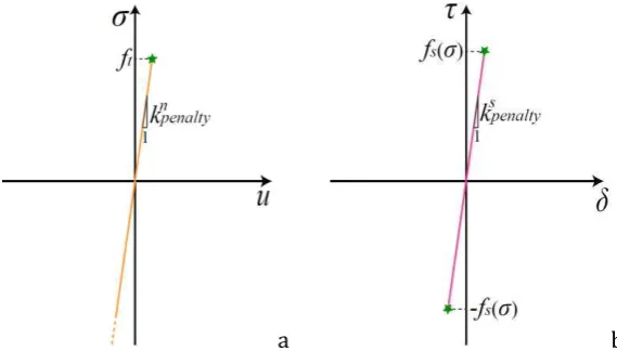
In the normal direction, the contact stress is computed by means of the linear relationship:
( 1 )
where is the penalty stiffness in normal direction and is the normal displacement. Through the contact penalty method, this relation is assumed to be valid also for tensile stresses until the tensile strength of the interface is reached, see Fig. 4a. As can be noted in Fig. 4a, penetration can occur between elements. However, although no procedures to remove penetration have been implemented, by using quite high penalty stiffnesses (i.e. equal to 500 times the stiffness of the underlying elements) the penetration between elements has been found negligible. Furthermore, the penalty stiffness adopted has been found a good compromise between convergence and accuracy (i.e. negligible penetration).
In the shear direction, the tangential slip is linearly related to the interface shear stress with the relation:
( 2 )
where is the penalty stiffness in shear. This relation is valid until the shear stress equals the shear strength , see Fig. 4b. The shear strength of the interface is assumed to be dependent on the contact stress:
tan ( 3 )
where tan and are parameters experimentally defined.
[image:7.595.169.454.342.504.2]a b
Fig. 4 – Interfacial pre-failure behaviour: a) normal behaviour and b) shear behaviour.
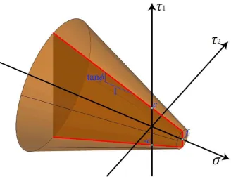
Interface failure occurs, i.e. the process of degradation begins, when the contact stresses at a point satisfy a failure criterion. Particularly, failure is supposed when the maximum contact stress ratio intersects a Mohr-Coulomb failure surface with tension cut-off. This simple criterion can be expressed as:
max
( 4 )
7
Fig. 5 – Interfacial failure surface: Morh-Coulomb surface with tension cut-off ( and are the shear stress components along two orthogonal directions in the plane of the interface).
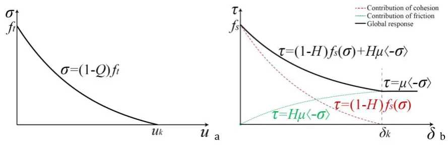
After reaching tensile strength , an interfacial cohesive behaviour is activated in normal direction and the stress decreases with an increasing separation , while at stress ends to be transmitted, see Fig. 6a. The stress follows the relationship:
( 5 )
where is an exponential scaling function defined as:
( 6 )
being a non-dimensional brittleness parameter and the maximum separation ever experienced by the contact point. The cohesive behaviour is only activated for tension, whereas for pure compression stress states no failure is considered at the interfacial level (see Fig. 5).
Concerning the shear behaviour, when the shear stress reaches the shear strength , a simplified cohesive-frictional behaviour is activated, and the contacting surfaces start sliding. After failure the shear stress is composed of a cohesive term and a frictional one (Fig. 6b), according to the relationship:
( 7 )
where is the ultimate slip of the cohesive behaviour, is the frictional coefficient and is an exponential scaling function defined as:
( 8 )
being a non-dimensional brittleness parameter and the maximum slip ever experienced by the contact point.
[image:8.595.142.471.77.329.2]8 adoption can be considered approximated, it is, however, more realistic than considering the independent the two phenomena. In particular, the two variables and can increase from 0 to 1 only. Indeed, the degradation of the cohesion is an irreversible process.
[image:9.595.91.536.143.288.2]a b
Fig. 6 – Interfacial post-failure behaviour: a) tensile response and b) shear response.
This model is, in general, not restricted to the monotonic behaviour. The degradation of cohesion is an irreversible process and once the maximum degradation has been reached, the cohesive contribution to the tensile and shear stresses is zero, and the only contribution to the shear stresses is from the frictional term.
The interface behaviour is based on large displacements. In particular, the finite-sliding tracking approach implemented in Abaqus [44], which allows for arbitrary separation, sliding, and rotation of the surfaces, is adopted.
3.1 Comparison between experimental and numerical results for small-scale masonry specimens
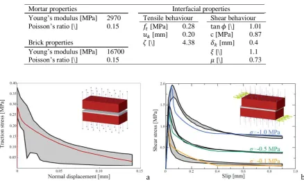
Experimental tests conducted by van der Pluijm in [2, 39] on small-scale masonry specimens, composed of two bricks jointed together by a mortar joint, were used as reference to compare with numerical outcomes and to tune the shape parameters and . As in [2, 39] the tensile and shear failures were only observed in the brick-mortar interfaces, linear elastic behaviour for brick and mortar has been assumed. The mechanical properties adopted in the numerical simulations are collected in Table 1. Fig. 7 shows the comparison between experimental and numerical results for small scale masonry specimens subjected to tension (Fig. 7a) and shear (Fig. 7b).
The tensile properties of the interface are assumed to be consistent with the fracture energy of the brick-mortar interface in tension (Mode I), which in [2] is equal to N/m. Indeed, once the tensile strength
and the displacement are fixed, which can be defined directly from the experimental envelope (Fig. 7a), the shape parameter is chosen so that the area under the curve in Fig. 6a equals .
Analogously, the shear properties of the interface are assumed to be consistent with the Mode II-fracture energy of the brick-mortar interface, which, in [39], follows the relation N/m (with in MPa). In this case, tan , , and are defined directly from the experimental outcomes [39], whereas the shape parameter is chosen to be the best approximation of for the three experimental curves in Fig. 6b.
9 Table 1. Mechanical properties for small-scale masonry specimens.
Mortar properties Interfacial properties
Young’s modulus [MPa] 2970 Tensile behaviour Shear behaviour
Poisson’s ratio [\] 0.15 [MPa] 0.28 tan [\] 1.01
[mm] 0.20 c [MPa] 0.87
Brick properties [\] 4.38 [mm] 0.4
Young’s modulus [MPa] 16700 [\] 1.1
Poisson’s ratio [\] 0.15 [\] 0.73
a b
10 4 Brick and mortar nonlinear behaviour
Tensile and compressive plastic-damage nonlinear behaviour is assumed for brick and mortar, based on the plastic-damage model developed by Lee and Fenves [43] for quasi-brittle materials. In the following, the main features of the model are recalled.
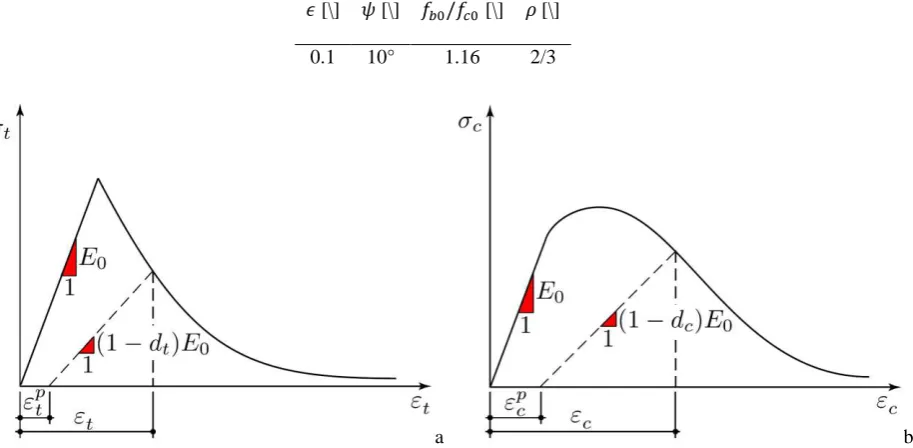
Two independent scalar damage variables, one for the tensile regime ( ) and one for the compressive regime ( ), are supposed. Accordingly, the stress-strain relations under uniaxial tension, , and compression, , are:
( 9 )
where is the initial Young’s modulus of the material, and are the uniaxial tensile and compressive strains, and and are the uniaxial tensile and compressive plastic strains (Fig. 8). Particularly, the curves depicted in Fig. 8 represent the main input data of the model.
Mesh objectivity in the softening branch passes through an indirect definition of the fracture energy, i.e. the model is local, and regularization occurs scaling the fracture energies by means of the equivalent length
det where and are the weight factors of the Gaussian integration scheme, the Jacobian of the transformation, the element area and a modification factor that depends on the typology of the finite element used. In this way, the mesh size does not significantly influence the material response.
Additionally, to control the dilatancy in the quasi-brittle material response, a nonassociative flow rule is considered to define the plastic strain rate. It is obtained by a flow rule generated by a Drucker-Prager type plastic potential. In particular, it is defined by the dilatancy angle , typically assumed equal to 10° in agreement with experimental evidences [45] and previous numerical models [46, 47], and a smoothing constant
generally assumed equal to 0.1 [46].
[image:11.595.81.538.532.756.2]As regard as the yield surface, a multiple-hardening Drucker-Prager type surface is assumed. It is characterized by the ratio between the biaxial initial compressive strength and the uniaxial initial compressive strength and a constant , which represents the ratio of the second stress invariant on the tensile meridian to that on the compressive meridian at initial yield. Typically, and for quasi-brittle materials [48]. The general parameters adopted for quasi-brittle materials, such as brick and mortar, are collected in Table 2.
Table 2. General parameters for quasi-brittle materials (brick and mortar).
[\] [\] [\] [\]
0.1 10° 1.16 2/3
a b
11 5 Numerical examples
Experimental-numerical comparisons for the in-plane and out-of-plane behaviours of masonry panels are here provided to show the effectiveness and the accuracy of the model proposed. The detailed micro-model herein proposed has been implemented in Abaqus Standard [44]. Geometric nonlinearity is considered in all the analyses to account for large-displacement effects.
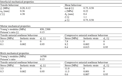
Experimental tests conducted by Vermeltfoort and Raijmakers [49] and by Chee Liang [50] are considered for the in-plane and out-of-plane response of masonry panels, respectively. Mechanical properties utilized for the in-plane and out-of-plane benchmarks are collected in Table 3. When more than one value is given in the same cell of the table, the first value refers to the in-plane benchmark, whereas the second one refers to the out-of-plane benchmark. In general, the tensile response of masonry joints is defined in terms of the tensile strength and fracture energy in tension (Mode I), whereas the shear response of masonry joints is defined in terms of friction, cohesion, residual friction and Mode II-fracture energy. It appears clear that and will be derived from the value of fracture energy in tension (Mode I), whereas and will be derived from the value of Mode II-fracture energy. To this aim, the shape parameters and have been kept equal to the ones of Section 3.1, and the values and have been chosen so that the fracture energy values were satisfied. Reference to [51] has been made to define the uniaxial inelastic stress-strain relationships. The evolution of the degradation damage scalar variables and has been kept substantially proportional to the decay of the uniaxial stresses, as successfully experienced is several numerical campaigns [46, 13, 52].
Concerning the in-plane benchmark, the mechanical properties for brick, mortar and brick–mortar interfaces employed in the analyses (Table 3) were reported in previous research [16, 18, 27]. In addition, the tensile strength of mortar has been assumed with reference to the results on mortar prisms obtained in the experimental campaign carried out in the TU Delft laboratories in 1991 [2].
12
Table 3. Mechanical properties utilized for the in-plane and out-of-plane benchmarks. When more than one value is given in the same cell, the first value refers to the in-plane benchmark, whereas the second one refers to the out-of-plane
benchmark.
Interfacial mechanical properties
Tensile behaviour Shear behaviour
[MPa] 0.20, 0.12 tan [\] 0.75, 0.58
[mm] 0.36 c [MPa] 0.22
[\] 4.38 [mm] 0.4
[\] 1.1
[\] 0.75, 0.58
Mortar mechanical properties
Young’s modulus [MPa] 850, 2300
Poisson’s ratio [\] 0.15
Tensile uniaxial nonlinear behaviour Compressive uniaxial nonlinear behaviour
Stress [MPa] Inelastic strain [\] Stress [MPa] Inelastic strain [\]
1.5 0 0 7.8 0 0
0.1 0.002 0.95 8.2 0.002 0
0.4 0.015 0.95
Brick mechanical properties
Young’s modulus [MPa] 16700
Poisson’s ratio 0.15
Tensile uniaxial nonlinear behaviour Compressive uniaxial nonlinear behaviour
Stress [MPa] Inelastic strain [\] Stress [MPa] Inelastic strain [\]
3.5 0 0 11.0 0 0
0.3 0.002 0.95 11.5 0.001 0
0.6 0.007 0.95
5.1 In-plane response
Results obtained by Vermeltfoort and Raijmakers [49] in shear tests on single-leaf panels are here considered. The identical wall specimens, named J4D, J5D and J7D in [49], with a length (990 mm) to height (1000 mm) ratio of approximately 1 were considered (Fig. 9). They are characterized by 18 brick layers of which 2 were fixed to steel beams so as to keep the top and bottom edges of the element straight during the test (green zones in Fig. 9a). Each brick is 204mm ×98mm ×50mm, whereas the bed and head mortar joints are 12.5mm thick. Particularly, the masonry panels were initially preloaded with a vertical top pressure, Pv=0.3MPa for J4D and J5D and Pv=2.12MPa for J7D. Then a horizontal load was then applied in the plane of the walls at the top edge under displacement control up to collapse, see Fig. 9a.
During the tests, first, horizontal cracks appeared at the top and bottom of the walls. Then, cracks started to develop diagonally along the bed and head mortar joints and through the bricks, up to failure. The experimental response was characterized by a softening branch that started when diagonal cracks appeared in the centre of the specimens.
13
[image:14.595.113.498.71.215.2]a b
Fig. 9 – In-plane response of masonry wall panels [49]: a) boundary conditions and b) assembly of Representative Elements employed in the numerical model.
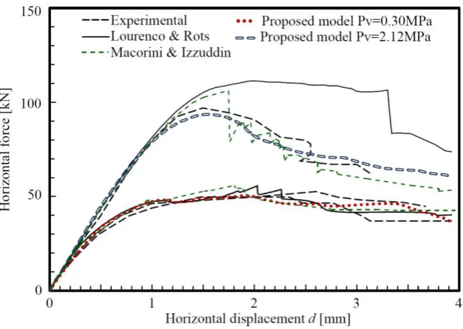
Fig. 10 provides experimental-numerical comparisons: the experimental load-displacement curves for J4D, J5D and J7D walls are compared with the numerical results carried out using a Representative Element mesh composed of 20 hexahedral 8-nodes FEs. In this figure, the numerical predictions reported by Lourenço & Rots [18] and by Macorini & Izzuddin [27] are also shown. A good agreement between experimental and numerical results can be observed up to collapse, including initial stiffness, maximum capacity and the post-peak response of the panels. Also, the predictions of the proposed modelling approach are generally close to those reported in [18, 27] for all the considered walls, with the current predictions of the post-peak response for wall J7D better than the one obtained in [18].
The discretization of the Representative Elements is explicitly chosen by the user. The role of the mesh size is shown in Fig. 11a, in which the influence of mesh refinement on the load-displacement curves is collected. The results obtained using a Representative Element mesh consisting of 20 hexahedral 8-nodes FEs (coarse mesh) and a Representative Element mesh consisting of 108 hexahedral 8-nodes FEs (fine mesh) are compared. As can be noted, very small discrepancies emerged. Thereby, mesh dependency appears negligible, also thanks to the regularization of the fracture energy in the continuum plastic-damage model. This aspect is particularly appealing as the analyses with the coarse mesh presented a computational cost considerably smaller than the fine mesh.
Fig. 11b shows the influence of the nonlinear behaviour of Representative Elements on the load-displacement curves. As can be noted, the fact of accounting for the cracking and crushing of Representative Elements significantly affects the post-peak behaviour (Fig. 11b), whereas the hypothesis of linear elastic Representative Elements slightly overestimates the peak load. Basically, it is expected that the differences in considering or not the nonlinear behaviour of Representative Elements would increase by increasing the vertical pressure as well as the interlocking of the masonry texture (e.g. for multi-leaf walls).
14
Fig. 10 – Experimental – numerical comparisons of the load – displacement curves for the masonry wall panels loaded in plane.
a b
[image:15.595.85.534.367.565.2]15
a b
[image:16.595.84.529.80.497.2]c d
Fig. 12 –Comparison of the panel’s crack pattern: a) tensile damage contour plot, b) compressive damage contour plot, c) interfaces which exhibited failure and d) experimental crack pattern for the specimen with Pv=2.12MPa (J7D in [49]).
5.2 Out-of-plane response
Numerical analyses are also carried out to assess the effectiveness of the detailed micro-modelling approach developed to investigate the out-of-plane behaviour of masonry panels, where comparisons are carried out against the experiments performed by Chee Liang [50].
16 To compute the solution up to the collapse of the panel (also in case of softening), a quasi-static direct-integration dynamic analysis procedure has been adopted [44]. This algorithm permits to study quasi-static responses in which inertia effects are introduced primarily to regularize unstable behaviours. The Authors experienced a better performance of this algorithm, specifically in the softening regime, with respect to more common arc length procedures.
Fig. 14 provides the numerical-experimental comparisons in terms of lateral pressure-transversal displacement curves, where the textured unit mesh composed of 20 hexahedral 8-nodes FEs, shown in Fig. 11a, has been implemented. Although the through-thickness discretization may play a certain role, especially in the out-of-plane analysis of multi-leaf walls [53], the utilization of two 8-nodes hexahedral FEs through-thickness appears sufficiently accurate for the case under study. The experimental results reported in [50] for the wall 8 and the wall 12 correspond to a partial load-displacement curve for wall 8, where the displacement considered is computed at the centre of the wall, and the maximum capacity for both walls. Good agreement between the numerical and experimental results can be observed. A maximum lateral pressure for the wall very close to the experimental capacity [50], to the collapse pressure determined in [54] through a 3D limit analysis approach and to the numerical curve obtained in [27], is obtained. Particularly, the curve obtained with the proposed approach very well fits the partial load-displacement curve for wall 8. Additionally, Fig. 15 provides the comparison between the experimental and numerical out-of-plane deflections at the instant, shown in Fig. 14 by means of a green point and a magenta point, with lateral pressure equal to 20 kN/m2, i.e. at an instant slightly prior to failure. Here again, a good numerical-experimental agreement is achieved in terms of out-of-plane deflections.
Finally, Fig. 16 shows the crack pattern obtained by means of the proposed model, in terms of deformed shape at collapse (Fig. 16a), out-of-plane displacement contour plot (Fig. 16b), tensile damage contour plot (Fig. 16c) and compressive damage contour plot (Fig. 16d). By comparing the numerical crack pattern of Fig. 16 with the experimental one (Fig. 13), it can be noted that the actual failure mechanism, although slightly different in the two walls, is qualitatively represented by the numerical model proposed. Particularly, the large vertical crack that runs in the middle of the panel crossing head mortar joints and bricks as well as the diagonal cracks observed in the tests are well represented. Indeed, as can be noted in Fig. 16c, tensile damage is experienced in the central part of the Representative Elements which are placed in the central vertical part of the wall, in agreement with the actual vertical cracks experienced by both walls (Fig. 13) which alternatively crosses the bricks. For the sake of comparison, the crack pattern obtained by numerical models consolidated in the scientific community [54, 27] is reported in Fig. 17. As can be noted, the crack pattern computed by the model here proposed (Fig. 16), is in good agreement with the ones depicted in Fig. 17.
[image:17.595.106.509.493.693.2]a b
17
Fig. 14 –Comparison of the lateral pressure – out-of-plane displacement curves.
[image:18.595.112.500.416.607.2]18
a b
[image:19.595.76.532.54.537.2]c d
19
a b
Fig. 17 – Crack pattern obtained by consolidated numerical models: a) Milani (2008) [54] and b) Macorini and Izzuddin (2011) [27].
6 Conclusions
In this paper, a novel numerical approach to model masonry has been proposed. Indeed, the 3D detailed micro-model presented consists of the coupling of contact-based rigid-cohesive interfaces with 3D nonlinear-damaging textured units (which explicitly account for the mortar layers), which is a novelty in the scientific literature. This novel modelling approach can, in fact, be fully characterized by the properties obtained on small-scale specimen tests on brick and mortar (stiffness, compressive and tensile responses) and on small masonry assemblages (tensile and shear responses of the mortar-brick bond).
According to the modelling approach proposed, masonry is composed of textured units consisting of one brick and few mortar layers represented by 3D solid FEs obeying to plastic-damage constitutive laws. This permits to represent the brick and mortar mechanical behaviour when cracking and/or crushing occur. Textured units are assembled, accounting for any actual 3D through-thickness arrangement of masonry (including walls with openings, multi-leaf walls, etc.), by means of zero-thickness cohesive-frictional interfaces based on the contact penalty method. This permits to account for the brick-mortar bond failures both in tension and shear.
To reach this goal, this paper introduced an interface model. Indeed, the interface behaviour assumed in the 3D detailed micro-model is governed by an ad-hoc modification of the standard surface-based contact behaviour implemented in Abaqus. Contextually, an automatic subroutine ad-hoc written by the authors has been implemented to reproduce a Mohr-Coulomb failure surface with tension cut-off.
The interfacial behaviour appeared to be consistent with experimental outcomes on small-scale masonry specimens. The results of numerical analyses carried out to investigate both the in-plane and the out-of-plane responses of brick-masonry panels up to collapse has been presented and compared with experimental outcomes. From this comparison, it was shown that the use of the proposed modelling approach allows the accurate representation of the masonry behaviour both in the in-plane and out-of-plane responses. The results achieved demonstrate the significant potential of the proposed approach.
[image:20.595.191.420.73.244.2]20
Table 4. Times required to conduct the analyses.
Simulation Time required(x) (hh:mm:ss)
In-plane coarse mesh (Pv=0.30MPa) 00:06:33
In-plane coarse mesh (Pv=2.12MPa) 00:07:18
In-plane fine mesh (Pv=2.12MPa) 00:23:20
Out-of-plane 00:09:11
(x) utilizing a commercial laptop equipped with a processor Intel®Core™
i7-6500U CPU @ 2.50GHz and 16GB RAM.
Finally, considering the accuracy of the model proposed, its application to simulate the behaviour of masonry panels under certain loading conditions can be used to help laboratory experimenters in designing new or optimizing experimental set-ups, in predicting the crack pattern, the maximum load and the ultimate displacement of scheduled tests.
ACKNOWLEDGEMENTS
Mauro Parodi, Massimo Damasio and Claudio Cavallero (http://www.exemplar.com/) are gratefully acknowledged for their technical support. Financial support by the Italian Ministry of Education, Universities
21 REFERENCES
[1] A. W. Hendry, Structural Masonry, UK: Palgrave MacMillan, 1998.
[2] R. van der Pluijm, “Material properties of masonry and its components under tension and shear,” in 6th Canadian Masonry Symposium, 15-17 June 1992, Saskatoon, Canada, 1992.
[3] C. Mazzotti, E. Sassoni and G. Pagliai, “Determination of Shear Strength of Historic Masonries
by Moderately Destructive Testing of Masonry Cores,” Construction and Building Materials, vol. 54, p. 421–431, 2014.
[4] A. Formisano and A. Marzo, “Simplified and Refined Methods for Seismic Vulnerability
Assessment and Retrofitting of an Italian Cultural Heritage Masonry Building,” Computers & Structures, vol. 180, p. 13–26, 2017.
[5] E. Sacco, D. Addessi and K. Sab, “New trends in mechanics of masonry,” Meccanica, vol. 53, no. 7, p. 1565–1569, 2018.
[6] P. B. Lourenço, “Computations on Historic Masonry Structures,” Progress in Structural Engineering and Materials, vol. 4, no. 3, p. 301–319, 2002.
[7] S. Marfia and E. Sacco, “Multiscale damage contact-friction model for periodic masonry walls,” Computer Methods in Applied Mechanics and Engineering, Vols. 205-208, p. 189–203, 2012.
[8] G. Giambanco, E. La Malfa Ribolla and A. Spada, “Meshless meso-modeling of masonry in the
computational homogenization framework,” Meccanica, 2017.
[9] G. Milani and A. Tralli, “Simple SQP approach for out-of-plane loaded homogenized brickwork
panels, accounting for softening,” Computers & Structures, vol. 89, no. 1-2, p. 201–215, 2011.
[10] S. Brasile, R. Casciaro and G. Formica, “Finite Element formulation for nonlinear analysis of
masonry walls,” Computers & Structures, vol. 88, no. 3-4, p. 135–143, 2010.
[11] P. Pegon and A. Anthoine, “Numerical Strategies for Solving Continuum Damage Problems with
Softening: Application to the Homogenization of Masonry,” Computers & Structures, vol. 64, no. 1-4, p. 623–642, 1997.
[12] J. Toti, V. Gattulli and E. Sacco, “Nonlocal Damage Propagation in the Dynamics of Masonry
Elements,” Computers & Structures, vol. 152, p. 215–227, 2015.
[13] G. Castellazzi, A. M. D’Altri, S. de Miranda, A. Chiozzi and A. Tralli, “Numerical Insights on the Seismic Behavior of a Non-Isolated Historical Masonry Tower,” Bulletin of Earthquake Engineering, vol. 16, no. 2, p. 933–961, 2018.
[14] L. Pelà, M. Cervera and P. Roca, “An Orthotropic Damage Model for the Analysis of Masonry
Structures,” Construction and Building Materials, vol. 41, p. 957–967, 2013.
[15] L. Berto, A. Saetta, R. Scotta and R. Vitaliani, “An Orthotropic Damage Model for Masonry
22 [16] M. Petracca, L. Pelà, R. Rossi, S. Zaghi, G. Camata and E. Spacone, “Micro-Scale Continuous
and Discrete Numerical Models for Nonlinear Analysis of Masonry Shear Walls,” Construction and Building Materials, vol. 149, p. 296–314, 2017.
[17] G. Vasconcelos and P. B. Lourenço, “In-Plane Experimental Behavior of Stone Masonry Walls
Under Cyclic Loading,” Journal of Structural Engineering, vol. 135, no. 10, p. 1269–1277, 2009.
[18] P. B. Lourenço and J. G. Rots, “Multisurface Interface Model for Analysis of Masonry
Structures,” Journal of Engineering Mechanics, vol. 123, no. 7, p. 660–668, 1997.
[19] L. Gambarotta and S. Lagomarsino, “Damage models for the seismic response of brick masonry
shear walls. Part I: the mortar joint model and its applications,” Earthquake engineering & structural dynamics, vol. 26, no. 4, pp. 423-439, 1997.
[20] L. Gambarotta and S. Lagomarsino, “Damage models for the seismic response of brick masonry
shear walls. Part II: the continuum model and its applications,” Earthquake engineering & structural dynamics, vol. 26, no. 4, pp. 441-462, 1997.
[21] G. Giambanco, S. Rizzo and R. Spallino, “Numerical Analysis of Masonry Structures via
Interface Models,” Computer Methods in Applied Mechanics and Engineering, vol. 190, no. 49-50, p. 6493–6511, 2001.
[22] G. Alfano and E. Sacco, “Combining Interface Damage and Friction in a Cohesive-Zone Model,” International Journal for Numerical Methods in Engineering, vol. 68, no. 5, p. 542–582, 2006.
[23] F. Parrinello, B. Failla and G. Borino, “Cohesive–frictional Interface Constitutive Model,” International Journal of Solids and Structures, vol. 46, no. 13, p. 2680–2692, 2009.
[24] F. Fouchal, F. Lebon and I. Titeux, “Contribution to the Modelling of Interfaces in Masonry
Construction,” Construction and Building Materials, vol. 23, no. 6, p. 2428–2441, 2009.
[25] E. Sacco and J. Toti, “Interface Elements for the Analysis of Masonry Structures,” International Journal for Computational Methods in Engineering Science and Mechanics, vol. 11, no. 6, p. 354– 373, 2010.
[26] A. Rekik and F. Lebon, “Identification of the Representative Crack Length Evolution in a Multi -Level Interface Model for Quasi-Brittle Masonry,” International Journal of Solids and Structures, vol. 47, no. 22-23, p. 3011–3021, 2010.
[27] L. Macorini and B. A. Izzuddin, “A Non-Linear Interface Element for 3D Mesoscale Analysis of Brick-Masonry Structures,” International Journal for Numerical Methods in Engineering, vol. 85, no. 12, p. 1584–1608, 2011.
[28] E. Minga, L. Macorini and B. A. Izzuddin, “Enhanced Mesoscale Partitioned Modelling of
Heterogeneous Masonry Structures,” International Journal for Numerical Methods in Engineering, 2017.
23 [30] D. Baraldi and A. Cecchi, “Discrete Approaches for the Nonlinear Analysis of in Plane Loaded
Masonry Walls: Molecular Dynamic and Static Algorithm Solutions,” European Journal of Mechanics - A/Solids, vol. 57, p. 165–177, 2016.
[31] G. Formica, V. Sansalone and R. Casciaro, “A Mixed Solution Strategy for the Nonlinear
Analysis of Brick Masonry Walls,” Computer Methods in Applied Mechanics and Engineering, vol. 191, no. 51-52, p. 5847–5876, 2002.
[32] J. V. Lemos, “Discrete Element Modeling of Masonry Structures,” International Journal of Architectural Heritage, vol. 1, no. 2, p. 190–213, 2007.
[33] S. Casolo, “Modelling in-Plane Micro-Structure of Masonry Walls by Rigid Elements,” International Journal of Solids and Structures, vol. 41, no. 13, p. 3625–3641, 2004.
[34] H. Smoljanović, Ž. Nikolić and N. Živaljić, “A Combined Finite–discrete Numerical Model for
Analysis of Masonry Structures,” Engineering Fracture Mechanics, vol. 136, pp. 1-14, 2015.
[35] V. Beatini, G. Royer-Carfagni and A. Tasora, “A Regularized Non-Smooth Contact Dynamics
Approach for Architectural Masonry Structures,” Computers & Structures, vol. 187, p. 88_100, 2017.
[36] D. Baraldi and A. Cecchi, “Discrete and continuous models for static and modal analysis of out
of plane loaded masonry,” Computers & Structures, 2017.
[37] T. Bui, A. Limam, V. Sarhosis and M. Hjiaj., “Discrete Element Modelling of the in-Plane and Out-of-Plane Behaviour of Dry-Joint Masonry Wall Constructions,” Engineering Structures, vol. 136, p. 277–294, 2017.
[38] R. Weyler, J. Oliver, T. Sain and J. Cante, “On the Contact Domain Method: A Comparison of
Penalty and Lagrange Multiplier Implementations,” Computer Methods in Applied Mechanics and Engineering, vol. 205–208, p. 68–82, 2012.
[39] R. van der Pluijm, “Shear behaviour of bed joints,” in 6th North American Masonry Conference, 6-9 June 1993, Philadelphia, Pennysylvania, USA, 1993.
[40] R. Serpieri, M. Albarella and E. Sacco, “A 3D Microstructured Cohesive–frictional Interface
Model and Its Rational Calibration for the Analysis of Masonry Panels,” International Journal of Solids and Structures, vol. 122–123, p. 110–127, 2017.
[41] M. Godio, I. Stefanou and K. Sab, “Effects of the dilatancy of joints and of the size of the building
blocks on the mechanical behavior of masonry structures,” Meccanica, 2017.
[42] R. van der Pluijm, H. Rutten and M. Ceelen, “Shear behaviour of bed joints,” in Proceedings of the Twelfth International Brick/Block Masonry Conference, 2000.
[43] J. Lee and G. L. Fenves, “Plastic-Damage Model for Cyclic Loading of Concrete Structures,” Journal of Engineering Mechanics, vol. 124, no. 8, p. 892–900, 1998.
[44] Abaqus®. Theory manual, version 6.14, 2014.
24 [46] G. Milani, M. Valente and C. Alessandri, “The Narthex of the Church of the Nativity in
Bethlehem: A Non-Linear Finite Element Approach to Predict the Structural Damage,” Computers & Structures, 2017.
[47] G. Castellazzi, A. M. D’Altri, S. de Miranda and F. Ubertini, “An Innovative Numerical
Modeling Strategy for the Structural Analysis of Historical Monumental Buildings,” Engineering Structures, vol. 132, p. 229–248, 2017.
[48] J. Lubliner, J. Oliver, S. Oller and E. Oñate, “A Plastic-Damage Model for Concrete,” International Journal of Solids and Structures, vol. 25, no. 3, p. 299–326, 1989.
[49] A. T. Vermeltfoort and T. M. J. Raijmakers, “Deformation controlled meso shear tests on masonry piers - part 2,” Draft Report, Department of BKO, TU Eindhoven, 1993.
[50] N. Chee Liang, “Experimental and theoretical investigation of the behavior of brickwork
cladding panel subjected to lateral loading,” Ph.D. thesis University of Edinburgh, 1996.
[51] H. B. Kaushik, D. C. Rai and S. K. Jain, “Stress-Strain Characteristics of Clay Brick Masonry
Under Uniaxial Compression,” Journal of Materials in Civil Engineering, vol. 19, no. 9, p. 728–739, 2007.
[52] A. M. D’Altri, G. Castellazzi, S. de Miranda and A. Tralli, “Seismic-Induced Damage in Historical Masonry Vaults: A Case-Study in the 2012 Emilia Earthquake-Stricken Area,” Journal of Building Engineering, vol. 13, p. 224–243, 2017.
[53] S. Casolo and G. Milani, “Simplified out-of-plane modelling of three-leaf masonry walls
accounting for the material texture,” Construction and Building Materials, vol. 40, p. 330–351, 2013.
![Fig. 1 – Modelling strategies for masonry structures (following [6, 16]): a) masonry sample, b) detailed micro-modelling, c) continuous micro-modelling, d) discrete micro-modelling and e) macro-modelling](https://thumb-us.123doks.com/thumbv2/123dok_us/1942082.154238/6.595.85.547.122.344/modelling-strategies-structures-modelling-continuous-modelling-modelling-modelling.webp)
![Fig. 9 – In-plane response of masonry wall panels [49]: a) boundary conditions and b) assembly of Representative Elements employed in the numerical model](https://thumb-us.123doks.com/thumbv2/123dok_us/1942082.154238/14.595.113.498.71.215/response-boundary-conditions-assembly-representative-elements-employed-numerical.webp)
![Fig. 12 –plot, c) interfaces which exhibited failure and d) experimental crack pattern for the specimen with Pv=2.12MPa (J7D in [49])](https://thumb-us.123doks.com/thumbv2/123dok_us/1942082.154238/16.595.84.529.80.497/fig-interfaces-exhibited-failure-experimental-crack-pattern-specimen.webp)