Electrical and Electronic Engineering Copyright. The copy of record is available at IEEE Xplore Digital Library.
Abstract—When a pole-to-pole dc fault occurs in a multi-terminal HVDC system, it is desirable that the stations and dc solid-state transformers on healthy cables continue contributing to power transfer, rather than blocking. To reduce the fault current of a modular multilevel converter based dc solid-state transformer, active fault current control is proposed, where the dc and ac components of fault arm currents are regulated independently. By dynamically regulating the dc offset of the arm voltage rather than being set at half the rated dc voltage, the dc component in the fault current is reduced significantly. Additionally, reduced ac voltage operation of the dc solid-state transformer during the fault is proposed, where the ac voltage of transformer is actively limited in the controllable range of both converters in the transformer to effectively suppress the ac component of the fault current. The fault arm current peak and the energy absorbed by the surge arrester in the dc circuit breakers are reduced by 31.8% and 4.9% respectively, thereby lowering the capacities of switching devices and circuit breakers. Alternatively, with the same fault current level, the dc-link node inductance can be halved by using the proposed control, yielding lowered cost and volume. The novel active fault current control mechanism and the necessary control strategy are presented and simulation results confirm its feasibility.
Index Terms—Active fault current control, average model, dc fault protection, dc solid-state transformer, modular multilevel converter (MMC), multi-terminal HVDC system, ride-through operation.
I. INTRODUCTION
C fault protection is an issue to be resolved for the development of modular multilevel converter (MMC) based HVDC transmission systems. [1-4]. The dc circuit breakers (DCCBs), including mechanical DCCBs, solid-state DCCBs, and hybrid DCCBs, have the potential to isolate a dc fault and protect stations from damage. However, the response of conventional mechanical DCCBs is slow and converter semiconductors endure high current stress during the response time [5-7]. The solid-state DCCBs can rapidly isolate a fault
This work was supported by the EPSRC under Grants EP/K006428/1 and EP/K035096, and the NSFC under Grant 51261130484.
R. Li, L. Xu, and B.W. Williams are with the Department of Electronic & Electrical Engineering, University of Strathclyde, Glasgow, G1 1XW UK (e-mail: rui.li@strath.ac.uk, lie.xu@strath.ac.uk, b.w.williams@eee.strath.ac.uk).
L.Z. Yao is with China Electric Power Research Institute, Xiaoying Road, Beijing, 100192, China (email: yaoliangzhong@epri.sgcc.com.cn).
but at high capital cost and significant on-state losses. Hybrid dc circuit breakers can clear a fault in milliseconds but have a large footprint and high capital cost [8, 9].
In [10], limiting reactors are series connected with the fast acting DCCBs (e.g. solid-state DCCBs, hybrid DCCBs) to limit the fault current di/dt and decrease the fault current peak. However, all the system stations are blocked during the fault to avoid overcurrents, causing shutdown of the entire terminal HVDC system. The ride-through operation of a multi-terminal HVDC system is presented in [11, 12], where additional series dc inductors and slow DCCBs are used to limit the fault current increase rate and isolate the fault. For a dc fault applied at the dc-link node, the stations connected to the healthy branches of the HVDC system are far from the fault location so the fault has less influence.
Recently, the concept of the ‘dc solid-state transformer’ (DCT) has been proposed which uses active controlled power electronic components to optimize converter performance. By blocking all the converters of the dc solid-state transformer, dc faults can be isolated without significantly affecting the healthy system parts. Similar to the ac transformer, the dc solid-state transformer can adapt the dc voltage to any higher or lower voltage level. Due to the absence of common standards, current HVDC systems are built with different dc voltage levels [13-16]. Thus, the dc solid-state transformer appears the only approach to connect and interconnect existing HVDC links with different dc voltages. Additionally, the solid-state transformer can contribute to the power flow and dc voltage control which are required to operate the dc grid properly and efficiently. Moreover, the solid-state transformer can provide galvanic isolation for safety reasons and for the normal operation of converters connected in the multi-terminal HVDC system [9].
Solid-state transformers include the thyristor based solid-state transformer [17, 18], the dual-active bridge (DAB) transformer [19], and the MMC based transformer [20]. Due to extremely low switching losses and improved harmonic characteristics, the MMC based dc solid-state transformer is an attractive approach [21-23], so is considered in this paper. In [9], a terminal station with a different dc voltage rating is connected to the main HVDC link through a dc solid-state transformer. When a dc fault is applied at a dc cable, the solid-state transformer on the faulty cable can be blocked quickly to
Active Control of DC Fault Currents in DC
Solid-State Transformers during Ride-Through
Operation of Multi-Terminal HVDC Systems
Rui Li, Lie Xu,
Senior
Member, IEEE
, Liangzhong Yao,
Senior
Member, IEEE
, and Barry W.
Williams
Electrical and Electronic Engineering Copyright. The copy of record is available at IEEE Xplore Digital Library. isolate the fault from the healthy main HVDC link. Thus the
stations on main HVDC link can be operated continuously. However, a fault on the main HVDC link is not considered.
The aim of this study is to use active control of the dc fault currents to reduce current stresses on solid-state transformer and DCCBs during ride-through operation of the healthy parts of a multi-terminal HVDC system under a dc fault. The paper is organized as follows. In Section II, the radial three-terminal HVDC system incorporating a solid-state front-to-front dc transformer is presented. The fault current of a dc solid-state transformer during ride-through operation is analyzed in Section III. In Section IV, novel active control of the fault current is proposed, where the dc and ac components of fault currents are regulated independently. The active fault current control is assessed in Section V, considering a pole-to-pole dc fault at the dc-link node of a three-terminal HVDC system. Finally Section VI draws the conclusions.
II. RADIAL THREE-TERMINAL HVDC SYSTEM INCORPORATING A DC SOLID-STATE TRANSFORMER
A. System Configuration
Fig. 1 shows the radial three-terminal HVDC system being studied, where dc inductances and DCCBs are at the both ends of Cables 1 and 2 and one end of Cable 3 (T3) to limit the fault
current increase rate and isolate the fault. The other end of Cable 3 (O3) is connected to the dc-link node through a dc
solid-state transformer to isolate the fault on Cable 3 from the
main HVDC link and to match the dc voltage of station S3
(±300kV) to that of the main HVDC link (±400kV).
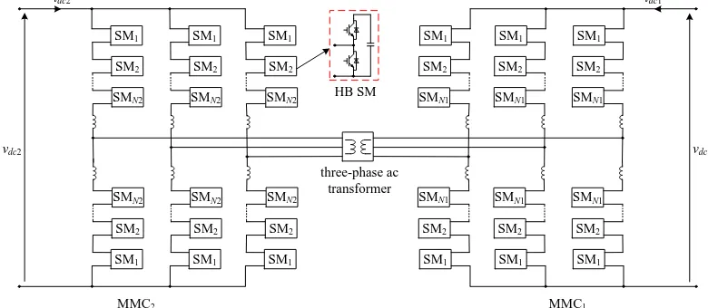
As shown in Fig. 2, the dc solid-state transformer is composed of two MMCs (MMC1 and MMC2) which are
front-to-front connected through a three-phase ac transformer. Both MMCs in the dc transformer, as well as the stations S1, S2, and
S3, employ the generic MMC topology with half-bridge (HB)
submodules (SMs). The dc transformer operates with sinusoidal waveforms on the ac side for controllability and good harmonic characteristics, compared to the quasi two-level control in [9].
Stations S1 and S3 regulate the dc voltages of the dc network,
while S2 injects rated active power P2 into ac grid G2. In the
solid-state transformer, MMC1 regulates the ac voltage while
MMC2 operates in an active power control mode and exports
rated power P3 from the main dc-link to the ac side. A
modified average model of the generic MMC is used for all the converters in Fig. 1 to reduce computation time and accelerate the simulation, as will be detailed in Section II C.
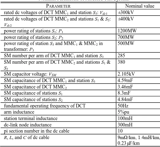
The parameter details of the test system are listed in Table I. The ac side voltages of the DCT are set to produce an approximate modulation index of 0.7, when sinusoidal modulation is used [24-26]. Each cable is modeled with 10 pi sections to simulate high frequency behavior during a fault and obtain satisfactory simulation accuracy [27, 28].
[image:2.612.63.548.398.525.2]Fig. 1. Radial three-terminal HVDC transmission system using average models of half-bridge based MMCs, incorporating a solid-state front-to-front dc transformer.
Fig. 2. DC solid-state transformer based on the generic MMC topology with half-bridge submodules.
G1 PCC1
400kV/342.93kV 0.2pu 15000MVA
X/R=14 Cable1 150km 1200MW
S1
G2
PCC2
342.93kV/400kV 0.2pu Cable2
100km
700MW
S2
500MW MMC2
500MW MMC1
G3
PCC3
257.2kV/400kV 0.2pu
5000MVA X/R=10 Cable3
100km
500MW
S3
8000MVA X/R=10
MMC based dc solid-state transformer
±400kV ±400kV
±300kV
LS2 P2
T2
LS3 P3
T3 LS1
P1
T1
BS1 O1 O2
O0
O3
342.93kV/257.2kV 0.2pu
LO3
BS2
BS3
BO1 LO1 LO2 BO2
SM1 SM1 SM1
SM2 SM2 SM2
SMN1
SMN1
SMN1
SM1 SM1 SM1
SM2 SM2 SM2
SMN1
SMN1
SMN1
HB SM
idc1
vdc1
SM1
SM1
SM1
SM2
SM2
SM2
SMN2 SMN2 SMN2
SM1
SM1
SM1
SM2
SM2
SM2
SMN2 SMN2 SMN2
idc2
vdc2
MMC1
MMC2
[image:2.612.109.499.558.728.2]Electrical and Electronic Engineering Copyright. The copy of record is available at IEEE Xplore Digital Library. As the active fault current control to be proposed does not
depend on the fundamental operating frequency of the dc transformer, the DCT MMCs are operated at 50Hz for simulation simplicity. With a higher operating frequency, for example, 500Hz, the SM capacitance, arm inductance, and three-phase ac transformer sizes can be reduced significantly, but at the expense of higher switching losses [29, 30].
TABLEI
Nominal Parameters of Modeled Test System.
PARAMETER Nominal value
rated dc voltages of DCT MMC1 and station S3: Vdc1 ±300kV rated dc voltages of DCT MMC2 and stations S1 & S2:
Vdc2
±400kV power rating of stations S1: P1 1200MW power rating of stations S2: P2 700MW power rating of station S3 and MMC1 & MMC2 in
transformer: P3
500MW SM number per arm of DCT MMC1 and station S3 285 SM number per arm of DCT MMC2 and stations S1 &
S2
380
SM capacitor voltage: VSM 2.105kV
SM capacitance of DCT MMC1 and station S3 4.59mF
SM capacitance of DCT MMC2 3.46mF
SM capacitance of stations S1 8.3mF
SM capacitance of stations S2 4.84mF
fundamental operating frequency of DCT 50Hz
arm inductance 5%pu
station terminal inductance 100mH
dc-link node inductance 300mH
pi section number in the dc cable 10
R, L, and C of dc cable 9mΩ/km, 1.4mH/km,
0.23µF/km
B. Consideration of DC Fault Ride-Through Operation
As the HB SMs do not have dc fault blocking capability, the high fault current flows through the SM freewheel diode, from the ac grid into the fault on the dc side, even if the MMC station is blocked. Thus, dc fault ride-through operation is a challenge for the development of HB based MMCs.
When a pole-to-pole dc fault occurs at Cable 3, MMC1 and
MMC2 in the transformer are both blocked to isolate the fault
from healthy stations S1 and S2. As the blocking time of IGBTs
is only several microseconds, the fault can be rapidly isolated by the solid-state transformer. Thus, a fault at Cable 3 does not expose the ride-through operation of stations S1 and S2 to
significant risk [9], and thus it is unnecessary to use the scheme to be proposed.
However, if a dc fault occurs at O2 as shown in Fig. 1, it is
desirable that stations S1 and S3 continue operating without
disrupting power transfer between S1 and S3 through the
solid-state transformer. This requires that there are no overcurrents in S1, S3 and the solid-state transformer during the fault period,
while the DCCBs isolate the fault from the rest of the dc network. If slow DCCBs with 10ms opening time are used [12, 31, 32], it is necessary to limit the fault current increase, especially in MMC2 of the transformer. As the fault is near
MMC2, its SM capacitors are rapidly discharged through node
inductors LO2 and LO3 (MMC2 cannot be blocked if dc fault
ride-through is to be achieved) and high ac currents are likely
due to the transformer ac voltages, via freewheel diodes. Thus the pole-to-pole dc fault at O2 is the most serious fault case for
ride-through operation of S1, S3 and the solid-state transformer,
thus is considered in this paper.
The arm current peak threshold is set at 2pu and the DCCBs are modeled with an opening time of 10ms, which is a typical time that can be achieved for the mechanical DCCBs [12, 31, 32].
C. Modified Average Model of Generic MMC
As MMCs typically use hundreds of SMs per arm in HVDC application, it is a burden to simulate the whole system using detailed switching models. To reduce computation time and accelerate the simulation, average models are used to evaluate MMC performance in normal operation and during a dc fault [33-35]. It is demonstrated in [33-35] that improved average models are applicable to pole-to-pole dc fault studies, with high accuracy.
However, the average model in [27] is only valid when the SM capacitance is large enough to maintain near constant SM capacitor voltage. One of the most important reasons is that only one equivalent capacitor is used in the MMC model. Thus the state equation that describes MMC behavior is significantly reduced, resulting in model inaccuracy [27].
[image:3.612.43.304.161.401.2]But the modified average model adopted in this paper, Fig. 3, uses 6 capacitors for the MMC and can represent the MMC behavior accurately under various operating conditions, including a pole-to-pole dc fault. Its derivation is based on the average models presented in [34-37] and the reference voltage and current for the controllable voltage and current sources and the IGBT switching logic are detailed in [36, 37] and [34] respectively.
Fig. 3. Modified average model of generic MMC with half-bridge submodules.
The modified average model in Fig. 3 provides reliable representation of MMC behavior during dc fault ride-through operation. This is achieved with the typical SM capacitance requirement of 30-40kJ/MVA as suggested by ABB in [38], which yields a capacitor voltage ripple in the range of ±10%. Compared to the average model with only one equivalent capacitance in [27], the modified average model in Fig. 3 reproduces MMC behavior during dc fault ride-through
Carm +
_ marmvc
i
vc
marmi
D2
Larm
D1
IGBT
DC cable
[image:3.612.315.561.439.606.2]Electrical and Electronic Engineering Copyright. The copy of record is available at IEEE Xplore Digital Library. operation without compromising accuracy [34, 35] and is
adopted in this paper.
As only one capacitor Carm is used per arm in Fig. 3, SM capacitor voltage balancing is not considered in the average model [27, 34, 39, 40]. By using a sorting algorithm, SM capacitor voltages during dc fault ride-through operation can be balanced in a detailed switching model [41-43].
III. FAULT CURRENT ANALYSIS OF THE DC SOLID-STATE TRANSFORMER
This section discusses the current behavior of the dc solid-state transformer, with conventional control, during a pole-to-pole dc fault.
A. DC Component in the Fault Current with Conventional Control
When a dc fault is applied at a dc cable, the solid-state transformer connected on the healthy cable continues operating. The generated upper and lower arm voltages of the MMC in the transformer are
½
u ref dc
v v V (1)
½
l ref dc
v v V (2)
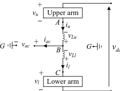
[image:4.612.312.570.156.377.2]where vref is the reference ac voltage of the MMC in the transformer; Vdc is the rated dc voltage; and u and l refer to the upper and lower arms, respectively.
Fig. 4. Equivalent circuit for one phase during ride-through without blocking the converter.
Assuming the dc voltage drop of the DCT MMC is Δvdc ( vdc 0) after a dc fault, the converter actual dc voltage vdc and the voltages between A and G (vAG), and C and G (vCG), as shown in Fig. 4, can be expressed as
dc dc dc
v V v (3)
½ ½
AG dc u ref dc
v v v v v (4)
½ ½ .
CG dc l ref dc
v v v v v (5)
Under normal operation, the dc voltage drop Δvdc is zero, thus the voltages vAG and vCG in Fig. 4 both equal the reference ac voltage vref, as depicted by (4) and (5). However, during the dc fault, vAG and vCG are not equal to vref due to the dc voltage drop Δvdc and the voltages across the upper and lower arm inductors, from (4) and (5), can be approximated as
½ ½ .
Lu Ll CG AG dc
v v v v v (6)
As a pole-to-pole dc fault results in significant dc voltage drop Δvdc, a large dc voltage of ½Δvdc is generated across the arm inductors. Consequently, high dc fault current results in the converter arms with conventional control.
To further analyze the behavior of the dc component in the
fault arm current, each MMC phase can be represented by the phase capacitor Cp in series with inductance Lp and resistance Rp, as shown in Fig. 5, where Cp, Lp and Rp are expressed as
2 , 2 , 2 .
p SM p arm p arm
C C N L L R R (7)
N is the number of SMs per arm; CSM is the SM capacitance; and Larm and Rarm are the inductance and resistance of the arm reactor.
As the initial voltage of Cp is the rated dc voltage Vdc, the fault arm current flowing through the switching devices can be derived from the equivalent circuit in Fig. 5 [33]:
1 1
0 2 2
1
1
( ) sin 1 sin( )
2
dc
f f f
f arm f
t t
v
i t e t I e t
L
(8)
where I0 is the initial current flowing through the switching
devices; 1 2 arm arm
L R
; 2
2 0
1
1
f
; 0 1
2 arm SM
N L C
; and
1 arctan f
.
Assuming the SM capacitor voltages are balanced in the fault mode, they are depicted by
1 2 2 1
1
( ) dc 1 sin( ) dc dc.
C f
f t
v V v
v t e t
N N
[image:4.612.112.235.369.463.2] (9)
Fig. 5. Equivalent phase capacitor discharging circuit.
Conventionally, the dc components of the arm voltages are controlled at half the rated dc voltage, even during a dc fault, to support the dc-link voltage. However, high dc components are generated in the fault arm currents due to the large dc voltage drop Δvdc during a dc fault and the dc components dominate the fault arm currents, as shown in (8). To reduce the dc component in the fault currents during a dc fault, the dc offsets of the arm voltages can be reduced, rather than being set at half the rated dc voltage. Based on this observation, active dc component control of the fault current is proposed, as detailed in Section IV A and C.
B. AC Component in the Fault Current
To regulate the ac current (iac, Fig. 4), the peak of ac phase voltage (vac in Fig. 4, referenced to the dc-link mid-point G) should be less than ½vdc, when sinusoidal modulation is adopted [24-26]. Initially following a remote dc fault, the actual dc voltage vdc of the DCT converter (MMC1 and MMC2,
Fig. 2) is higher than the threshold of vdcth defined by
th 2
dc m
v V (10)
where Vm is the peak (amplitude) of the ac phase voltage vac in Fig. 4. Thus, the DCT converter can control ac current (iac, Fig. 4) and dc components dominate in the fault arm currents, as mentioned. After the MMC actual dc voltage vdc falls below the threshold voltage vdcth, the DCT converter loses control of
ac currents and high currents are forced by the ac side voltage into the dc side.
The ac side voltages of stations S1, S2, and S3, Fig. 1, are
fixed and are determined by the grid voltage and the
Upper arm
+
–
vLu
A
B +
–
vLl
C +
–
vu
+
–
vl
G
Lower arm
dc
v iu
il
iac
G –vac +
Lp
Cp
Rp +
–vC
+ – +vL–
if
+
–
Electrical and Electronic Engineering Copyright. The copy of record is available at IEEE Xplore Digital Library. transformer ratio. For a solid-state transformer, the ac voltage
is set by one MMC in the transformer and is conventionally constant to guarantee maximum power transfer capability. In order to reduce the ac components in the fault arm currents, reduced ac voltage operation of the dc solid-state transformer is proposed and detailed in Section IV B and C.
IV. ACTIVE CONTROL OF THE FAULT CURRENT The fault arm current during a pole-to-pole dc fault is composed of dc and ac components. In this section, active fault current control is proposed where the dc and ac fault current components are independently controlled to suppress the fault arm currents.
A. Active DC Component Control of the Fault Arm Current
In order to reduce the dc component in the fault current, active dc component control of the fault current is proposed, where the dc offsets of the arm voltages are dynamically regulated. As the HB submodules cannot generate a negative voltage, the upper and lower arm voltages are depicted by
½ PID.out , PID.out 2
0, PID.out 2
dc ref dc ref
u
dc ref
V v V v
v
V v
(11)
½ PID.out , PID.out 2
0, PID.out 2
ref dc dc ref
l
dc ref
v V V v
v
V v
(12)
where PID.out is the output of the proposed active dc component control of the fault current and meets the requirement described by (13):
PID.out 0, in normal operation . PID.out 0, during a dc fault
(13)
According to (11) and (12), the voltages vAG and vCG can be expressed as
½ PID.out , PID.out 2
½ , PID.out 2
dc ref dc ref
AG
dc dc dc ref
v v V v
v
V v V v
(14)
½ PID.out , PID.out 2
.
½ , PID.out 2
dc ref dc ref
CG
dc dc dc ref
v v V v
v
V v V v
(15)
As a result, the voltages across the upper and lower arm inductors can be approximated as
½ PID.out , PID.out 2
¼ 2 PID.out 2 , PID.out 2 .
¼ 2 PID.out 2 , PID.out 2
dc dc ref
Lu Ll dc dc ref dc ref
dc dc ref dc ref
v V v
v v v V v V v
v V v V v
(16)
Comparing (16) to (6), the following equation can be derived when VdcPID.out2vref :
1 1
2 vdcPID.out 2 vdc. (17) This equation indicates that the voltages across the arm inductors are reduced by the output of the PID controller in the active dc component control, and thus, the fault currents are lowered by actively regulating the dc components of the arm voltages. As the HB SMs cannot generate negative voltages, the converter controllability of the dc components in the fault currents is limited in the conditions VdcPID.out 2vref and
PID.out 2
dc ref
V v . However, benefitting from the proposed reduced ac voltage operation of the solid-state transformer, as detailed in Section IV B and C, the DCT ac voltage is always limited to the converter controllable range. This not only reduces the fault current ac component, but also improves controllability of the fault current dc component.
B. Reduced AC Voltage Operation of the DC Solid-State Transformer
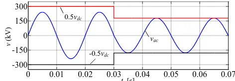
[image:5.612.319.555.423.505.2]To reduce the fault current ac component, solid-state transformer operation with reduced ac voltages is proposed, where the amplitude of the ac phase voltage (vac, Fig. 4) is actively limited in the controllable range of both transformer converters. Thus, the ac voltage contribution to the fault current is reduced. Fig. 6 illustrates the ac phase voltage in the ac component fault current control. During normal operation (t=0 to 0.03s), the peak of ac phase voltage (vac, Fig. 4) is lower than half the rated dc voltage (600kV) and the ac currents can be regulated. Assume the actual dc voltage of the DCT MMC (vdc, Fig. 4) drops below the original peak of phase voltage vac, after the dc fault is applied at a dc cable at t=0.03s. By using active fault current ac component control, the ac voltage peak is limited to half the reduced dc voltage to avoid inrush currents forced by the ac voltage. Due to the reduced ac voltage, the power transfer capability of the solid-state transformer is correspondingly lowered. But this reduces the fault current significantly and thus the solid-state transformer can be operated continuously rather than having to be blocked. Additionally, the dc circuit breaker capacity is reduced by the active control.
Fig. 6. AC phase voltage in the proposed reduced ac voltage operation of dc solid-state transformer.
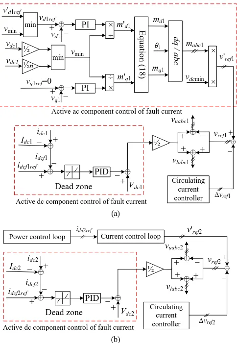
C. Active Fault Current Control Strategy
The proposed active fault current control is shown in Fig. 7. MMC1 in the solid-state transformer operates in an ac voltage
control mode and its control strategy is shown in Fig. 7 (a). MMC2 is assigned to control the active power with a control
strategy illustrated in Fig. 7 (b), where only active dc component control for the fault current is required and the reference voltage v'ref2 is set by the current control loop [44,
45].
After the fault occurs, the arm inductors suffer a high fault short-circuit voltage, as depicted by (6), which causes a rapid increase of fault currents. Thus, the active dc component control of fault current is required to have a fast response and the ability to predict the future error of the system response. PID control is thus used to effectively limit the dc component of the fault current, as shown in Fig. 7. The fault current dc
0 0.01 0.02 0.03 0.04 0.05 0.06 0.07
-300 -150 0 150 300
v
(
k
V
)
t [s]
vac
-0.5vdc
Electrical and Electronic Engineering Copyright. The copy of record is available at IEEE Xplore Digital Library. component is obtained by subtracting the rated dc current Idc
(Idc1 and Idc2, Fig. 7) from the actual dc current idc (idc1 and idc2,
Fig. 7) and is used as the feedback for the PID controller. During normal operation, the PID controller input is limited to zero by the dead zone block such that the arm voltage dc offsets are at their rated value. If the fault current is outside the predefined dead band, the PID controller output starts to increase from zero and regulates the arm voltage dc offsets continuously. The fault current band needs to be set such that active dc component control can quickly be enabled after the fault but avoid false activation under normal operation.
The ac voltage of the dc transformer needs to be controlled and coordinated between MMC1 and MMC2 to ensure
controllability of both MMC ac currents. As demonstrated in Fig. 7 (a), PI control sets the ac side voltage of the transformer. Compared with open loop control, PI control suppresses the dc voltage variation disturbance and thus the ac voltage can be accurately set to the reference value.
(a)
[image:6.612.56.298.273.623.2](b)
Fig. 7. Active control strategy of the dc solid-state transformer: (a) ac voltage control mode and (b) power control mode.
The reference voltages vd1ref and vq1ref, Fig. 7 (a), need to be set to limit the ac phase voltage to less than half the actual dc voltage. To achieve this, the d-axis reference voltage vd1ref is
obtained as
'
1 min 1 , min d ref d ref
v v v while the q-axis reference
voltage vq1ref is set at 0. v'd1ref is the original d-axis reference voltage and vmin is obtained from the minimum value of the
two dc voltages of the dc transformer:
1 1
2 2
min min dc1, dc2
v v nv ,
where n is the ac transformer ratio. Thus, the ac voltages of the dc transformer are always within the control range of both MMC1 and MMC2 when the actual dc voltage is lower than the
rated value. The inrush currents forced by the ac voltage are thus avoided by the proposed active ac component control of the fault current.
The minimum voltage vmin is the base voltage for the pu
values of the PI outputs m'd1 and m'q1, which are then limited
by (18) to avoid over-modulation and further limit the ac voltages within the converter control range:
' '
1 1
1 ' 2 ' 2 1 ' 2 ' 2
1 1 1 1
, q .
d
d q
d q d q
m m
m m
m m m m
(18)
The dc transformer operates with reduced ac voltage during the fault to lower the fault current and restores the rated value after the fault is isolated, in order to transfer rated power.
By independently regulating the dc and ac components in the fault currents, the proposed active control significantly reduces the fault currents. This implies the submodule capacitors are discharged by a smaller fault current and their voltages can be maintained higher during a dc fault. This characteristic improves converter controllability of the dc transformer and reduces oscillation during restoration after the fault is isolated. As the SM capacitors and the ac voltage provide less energy to the dc side fault, the converter actual dc voltage vdc under active control is lower than that with conventional control. Nevertheless, even with a lower converter dc voltage, the proposed active control still reduces the fault currents.
The proposed fault current control is achieved by actively regulating the reference waveforms for the upper and lower arms, rather than carrier waveforms. This makes it independent on the carrier waveform arrangement and is thus valid for both of the N+1 and 2N+1 modulations [46, 47].
As shown in Fig. 8 (b), even under the most severe pole-to-pole dc fault, the dc solid-state transformer with active control regulates the ac current as well as during normal operation. Additionally, by using active control, the maximum arm current peak is reduced from 2.2kA (2.6pu) to 1.5kA (1.8pu), that is, lowered by 31.8%, Fig. 8 (c) and (d). Alternatively, with 600mH inductances at the dc-link node as recommended in [12], the arm current peak is limited to 1.9pu without active fault current control. In other words, the dc-link node inductance can be halved by using the proposed active control, with the same fault current level (less than 2pu). This significantly lowers the cost and volume of dc-link node inductances.
Once a fault is detected (generally any dc fault is detected by monitoring the voltage across link inductors LS1,2,3 and
LO1,2,3), the circuit breaker BO2 is commanded to open with a
10ms opening time to isolate the fault from the healthy parts of the multi-terminal HVDC system. Due to the reduced fault current resulting from the proposed active control, the energy absorbed by surge arrestor in BO2 is reduced from 26.5MJ to
25.2MJ, a 4.9% reduction.
+
idcf1
idcf1ref
PID
_
+
Idc1
idc1
_ +
_
_ + +
vuabc1
+
vlabc1
Dead zone
+ +
+
+ +
Vdc1
vd1ref
PI
_ + +
vd1
× ÷
vdc1
min
vdc2
m'd1
m'q1
E
q
u
at
io
n
(
1
8
)
md1
mq1
d
q
/
a
b
c
mabc1
½n
½
vref1
Active dc component control of fault current
½
×
×
Δvref1
+
_ θ1
+
Active ac component control of fault current
Circulating current controller
v'ref1
÷ ×
vq1ref=0
PI
_ + +
vq1
vmin
vdcmin
v'd1ref
min
vmin
Power control loop
idq2ref
vref2
Current control loop
+
idcf2
idcf2ref
PID
_
+
Idc2
idc2
_ +
_
_ + +
vuabc2
+
vlabc2
Dead zone
+ +
+
+ +
Vdc2
Active dc component control of fault current
½
Δvref2
+
_+
Circulating current controller
Electrical and Electronic Engineering Copyright. The copy of record is available at IEEE Xplore Digital Library. V. PERFORMANCE EVALUATION DURING RIDE-THROUGH
OPERATION
The active fault current control during ride-through operation is assessed using the model in Fig. 1 with the parameters listed in Table I. The simulated scenario assumes the system in Fig. 1 is subjected to a permanent pole-to-pole dc fault at O2 at t=0.7s. As mentioned, the DCCBs isolate the
fault after 10ms from the fault initiation. Station S2 is blocked
after the detection of dc fault while S1, S3, and the dc
[image:7.612.56.288.177.408.2]solid-state transformer remain operational.
Fig. 8. Comparison between conventional control and the proposed active control: (a) three-phase ac currents with conventional control, (b) three-phase ac currents with active control, (c) arm currents with conventional control, and (d) arm currents with active control.
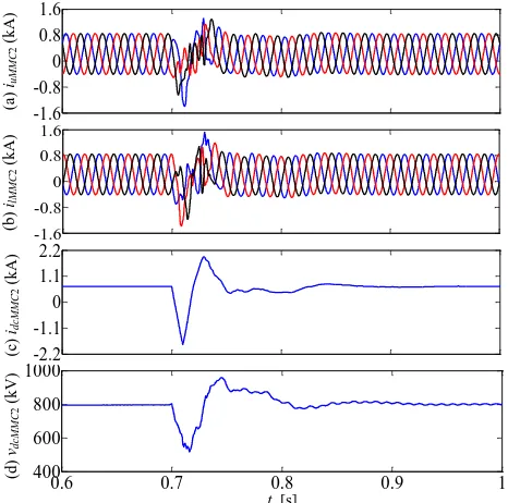
Fig. 9. Waveforms of MMC2 in the dc solid-state transformer: (a-b) upper and lower arm currents, (c) dc current, and (d) dc voltage.
A. DC Solid-State Transformer Performance
By virtue of the proposed active fault current control, the fault arm current peak of MMC2 in the transformer is reduced
to 1.8pu, lower than the current threshold (2pu), Fig. 9 (a) and (b). After the fault, the dc current of MMC2 changes direction
and reaches a maximum value of 1.9kA during the restoration period, Fig. 9 (c).
As MMC1 is decoupled from the fault by MMC2, the dc
fault influence on MMC1 is less than that on MMC2. The arm
currents, dc current and dc voltage of MMC1 present less
[image:7.612.321.553.196.423.2]disturbance during the fault, as observed in Fig. 10.
Fig. 10. Waveforms of MMC1 in the dc solid-state transformer: (a-b) upper and lower arm currents, (c) dc current, and (d) dc voltage.
Fig. 11. Waveforms at station S1: (a-b) upper and lower arm currents, (c) dc current, and (d) dc voltage.
B. Performance of Station Converters
The solid-state transformer is robust to dc faults, benefiting -2.6 -1.3 0 1.3 2.6 -2.6 -1.3 0 1.3 2.6 -2.6 -1.3 0 1.3
0.69 0.695 0.7 0.705 0.71 0.715
-2.6 -1.3 0 1.3 (a )
iab
c ( k A ) (c )
iarm
( k A ) (d )
iarm
( k A ) (b )
iabc
(
k
A
)
t [s]
0.6 0.7 0.8 0.9 1
400 600 800 1000 -1.6 -0.8 0 0.8 1.6 -1.6 -0.8 0 0.8 1.6 -2.2 -1.1 0 1.1 2.2 (a )
iuM
M C 2 ( k A ) (b ) ilM M C 2 ( k A ) (c )
idcM
M C 2 ( k A ) (d )
vdcM
M C 2 ( k V )
t [s]
0.2 0.4 0.6 0.8 1 (a )
iuM
M C 1 ( k A ) (b ) ilM M C 1 ( k A ) (c )
idcM
M C 1 ( k A ) (d )
vdcM
M C 1 ( k V )
t [s]
-1.5 -1 -0.5 0 0.5 1 -1.5 -1 -0.5 0 0.5 1
0.6 0.7 0.8 0.9 1
500 550 600 650 700 0 1 2 3 4 5 (a )
iuS
1 ( k A ) (b )
ilS1
( k A ) (c )
idcS
1 ( k A ) (d )
vdcS
1
(
k
V
)
t [s] -4 -2 0 2 -4 -2 0 2
0.6 0.7 0.8 0.9 1
[image:7.612.321.553.455.680.2] [image:7.612.58.291.459.690.2]Electrical and Electronic Engineering Copyright. The copy of record is available at IEEE Xplore Digital Library. from the new active fault current control. This makes it
possible to continuously operate the healthy stations (S1 and S3)
[image:8.612.57.292.116.344.2]in the dc network, even though the test system is subjected to the most severe type of dc fault (pole-to-pole dc fault) and typical slow DCCBs (10ms) are used to isolate the fault.
[image:8.612.315.556.176.247.2]Fig. 12. Waveforms at station S3: (a-b) upper and lower arm currents, (c) dc current, and (d) dc voltage.
Fig. 13. Waveforms at station S2 on the faulty branch: (a-b) upper and lower arm currents, (c) dc current, and (d) dc voltage.
The arm currents of station S1 are lower than 1.5pu, Fig. 11
(a) and (b). As station S3 is connected to the fault via the dc
transformer, which is robust to the dc fault, the fault disturbance on station S3 is much lower than that experienced
by station S1. S3 does not experience excessive overcurrents
during the fault, Fig. 12. The dc current of S1 increases after
the fault and reaches a peak of 4.1kA. Due to the different power direction and the robustness of the dc transformer to dc faults, the dc current of S3 decreases and does not change
direction. As station S2 is isolated from the healthy parts, the
steady-state dc current of S1 is reduced from 1.5kA to 0.6kA
after the fault, which is identical to that of MMC2 in the
transformer, Fig. 11 (c).
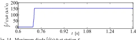
Station S2 is immediately blocked after fault detection and
circuit breaker BS2 is commanded to open with a 10ms delay,
in order to isolate the fault from S2 and protect the active
switches. In Fig. 13 and Fig. 14, the freewheel diodes suffer the fault currents due to the long opening time of the circuit breaker (10ms) and the maximum diode ∫i2(t)dt is 154kA2s.
Fig. 14. Maximum diode ∫i2(t)dt at station S 2. C. DC Circuit Breaker Stresses
Fig. 15 shows the waveforms of breaker BO2 which is
connected on the faulty branch at the dc-link node. The fault current flows through the mechanical switch until the switch opens at around t=0.71s. Then the current through the switch is commutated into the surge arrestor to limit the voltage across the circuit breaker, without exposing it to significant overvoltage. In Fig. 15 (b), the voltage across the circuit breaker is lower than 600kV (1.5pu). Only circuit breaker BO2
opens after detecting the fault at the dc-link node while BO1
and the dc transformer continue to transfer power between stations S1 and S3. As a result, the voltage across the surge
arrestor in BO1 is always around zero, so does not absorb
energy during the fault. All the opening energy is absorbed by the surge arrestor in BO2 and this energy is almost 25MJ, as
[image:8.612.57.290.375.605.2]shown in Fig. 15 (c).
Fig. 15. Waveforms of dc circuit breaker BO2 at dc-link node: (a) current, (b) voltage, and (c) DCCB absorbed energy.
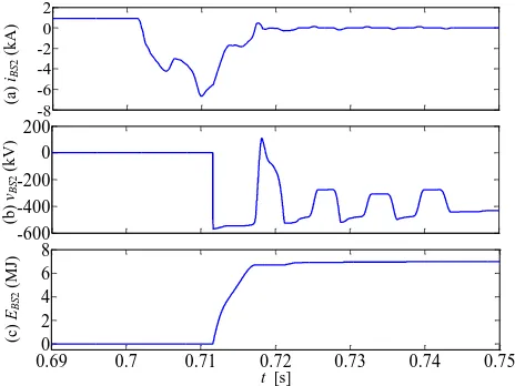
Besides BO2 (connected on the faulty branch at the dc-link
node) opening, breaker BS2 at the terminals of station S2 also
needs to open to protect station S2 converter. As shown in Fig.
16, circuit breaker overvoltage is avoided and the energy absorbed by the surge arrestor in DCCB BS2 is less than 7MJ.
The simulated pole-to-pole dc fault, which is the most
0.2 0.4 0.6 0.8 1
(a
)
iuS
3
(
k
A
)
(b
)
ilS3
(
k
A
)
(c
)
idcS
3
(
k
A
)
(d
)
vdcS
3
(
k
V
)
t [s]
-0.7 0 0.7 1.4
-0.7 0 0.7 1.4
0.6 0.7 0.8 0.9 1
500 550 600 650 700
-8 -6 -4 -2 0 2
(a
)
iuS
2
(
k
A
)
(b
)
ilS2
(
k
A
)
(c
)
idcS
2
(
k
A
)
(d
)
vdcS
2
(
k
V
)
t [s] -6
-4 -2 0 2
-6 -4 -2 0 2
0.6 0.7 0.8 0.9 1
-900 0 900 1800
0.6 0.76 0.92 1.08 1.24 1.4
0 50 100 150 200
t [s]
22(
)
(k
A
s)
i
t
d
t
(a
)
iBO
2
(
k
A
)
(b
)
vBO
2
(
k
V
)
(c
)
EB
O
2
(
M
J)
t [s] 0
2 4 6
0 200 400 600
0.69 0.7 0.71 0.72 0.73 0.74 0.75
[image:8.612.321.553.464.635.2]Electrical and Electronic Engineering Copyright. The copy of record is available at IEEE Xplore Digital Library. serious fault case for ride-through operation of the dc
transformer, causes disturbance for the converters on the healthy branches, especially for DCT MMC2, as it is close to
the fault location. However, benefitting from the proposed active fault current control, the fault currents are significantly reduced and the submodule capacitor voltages are maintained higher during a dc fault, which improves dc transformer converter controllability and reduces oscillation during restoration, after the fault is isolated. All the fault currents are lower than the threshold (2pu) and the healthy parts are gradually restored to normal operation. DC fault ride-through operation of multi-terminal HVDC systems is thus achieved.
Fig. 16. Waveforms of dc circuit breaker BS2 at terminal of station S2: (a) current, (b) voltage, and (c) DCCB absorbed energy.
VI. CONCLUSION
This paper proposes active fault current control of the dc solid-state transformer during a pole-to-pole dc fault, where the dc and ac components of the fault currents are independently suppressed. The mechanism of the novel active control was analyzed and a control strategy was presented. By dynamically regulating the dc offsets in the arm voltages rather than being set at half the rated dc voltage, the dc component in fault current is reduced by the proposed active control. The ac component in the fault current is also effectively lowered with the proposed reduced ac voltage operation of the dc transformer where the ac side voltage of transformer is actively limited in the controllable range of both transformer converters. The maximum arm current peak and the energy absorbed by surge arrestor in the dc circuit breaker are reduced by 31.8% and 4.9% respectively, and thus devices with low power capacity can be potentially used, yielding reduced losses and capital cost. The dc-link inductance can be halved that recommended in [12] by using active control thus the cost and volume of the dc-link inductors are decreased. System ride-through operation with a dc fault on the main HVDC link is achieved without exposing the dc transformer or station converters to significant fault currents and overvoltages.
VII. REFERENCES
[1] G. P. Adam, K. H. Ahmed, S. J. Finney, K. Bell, and B. W. Williams, "New Breed of Network Fault-Tolerant Voltage-Source-Converter HVDC Transmission System," IEEE Trans. Power Sys., vol. 28, pp. 335-346, 2013.
[2] P. Samuel, R. Gupta, and D. Chandra, "Grid interface of wind power with large split-winding alternator using cascaded multilevel inverter," in
IEEE Trans. Energy Convers vol. 26, ed, 2011, pp. 299-309.
[3] M. Hamzeh, A. Ghazanfari, H. Mokhtari, and H. Karimi, "Integrating Hybrid Power Source Into an Islanded MV Microgrid Using CHB Multilevel Inverter Under Unbalanced and Nonlinear Load Conditions,"
IEEE Trans. Energy Convers, vol. 28, pp. 643-651, 2013.
[4] R. Li, J. E. Fletcher, L. Xu, D. Holliday, and B. W. Williams, "A Hybrid Modular Multilevel Converter with Novel Three-level Cells for DC Fault Blocking Capability," IEEE Trans. Power Del., vol. PP, pp. 1-1, 2015. [5] M. K. Bucher, M. M. Walter, M. Pfeiffer, and C. M. Franck, "Options for
ground fault clearance in HVDC offshore networks," in Energy Conversion Congress and Exposition (ECCE), 2012 IEEE, 2012, pp. 2880-2887.
[6] B. Kroposki, C. Pink, R. DeBlasio, H. Thomas, M. Simoes, and P. K. Sen, "Benefits of power electronic interfaces for distributed energy systems,"
IEEE Trans. Energy Convers, vol. 25, pp. 901-908, 2010.
[7] M. Firouzi and G. Gharehpetian, "Improving fault ride-through capability of fixed-speed wind turbine by using bridge-type fault current limiter,"
IEEE Trans. Energy Convers, vol. 28, pp. 361-369, 2013.
[8] C. Meyer, M. Kowal, and R. W. De Doncker, "Circuit breaker concepts for future high-power DC-applications," in Industry Applications Conference, 2005. Fourtieth IAS Annual Meeting. Conference Record of the 2005, 2005, pp. 860-866 Vol. 2.
[9] I. A. Gowaid, G. P. Adam, A. M. Massoud, S. Ahmed, D. Holliday, and B. W. Williams, "Quasi Two-Level Operation of Modular Multilevel Converter for Use in a High-Power DC Transformer With DC Fault Isolation Capability," IEEE Trans. Power Electron., vol. 30, pp. 108-123, 2015.
[10] E. Kontos, R. T. Pinto, S. Rodrigues, and P. Bauer, "Impact of HVDC Transmission System Topology on Multiterminal DC Network Faults,"
IEEE Trans. Power Del., vol. PP, pp. 1-1, 2014.
[11] R. Li, J. E. Fletcher, L. Yao, and B. W. Williams, "DC fault protection structures at a DC-link node in a radial multi-terminal high-voltage direct current system," IET Renewable Power Generation, 2016.
[12] G. Adam, R. Li, D. Holliday, S. Finney, L. Xu, B. Williams, et al., "Continued Operation of Multi-Terminal HVDC Networks Based on Modular Multilevel Converters," CIGRE, pp. 1-8, 2015.
[13] R. Blasco-Gimenez, N. Aparicio, S. Ano-Villalba, and S. Bernal-Perez, "LCC-HVDC Connection of Offshore Wind Farms With Reduced Filter Banks," IEEE Trans. Ind. Electron., vol. 60, pp. 2372-2380, 2013. [14] S. Bernal-Perez, S. Ano-Villalba, R. Blasco-Gimenez, and J.
Rodriguez-D'Derlee, "Efficiency and Fault Ride-Through Performance of a Diode-Rectifier- and VSC-Inverter-Based HVDC Link for Offshore Wind Farms," IEEE Trans. Ind. Electron., vol. 60, pp. 2401-2409, 2013. [15] M. Saeedifard, R. Iravani, and J. Pou, "A Space Vector Modulation
Strategy for a Back-to-Back Five-Level HVDC Converter System," IEEE Trans. Ind. Electron., vol. 56, pp. 452-466, 2009.
[16] L. Yong, L. Longfu, C. Rehtanz, W. Can, and S. Ruberg, "Simulation of the Electromagnetic Response Characteristic of an Inductively Filtered HVDC Converter Transformer Using Field-Circuit Coupling," IEEE Trans. Ind. Electron., vol. 59, pp. 4020-4031, 2012.
[17] M. Hajian, J. Robinson, D. Jovcic, and W. Bin, "30 kW, 200 V/900 V, Thyristor LCL DC/DC Converter Laboratory Prototype Design and Testing," IEEE Trans. Power Electron., vol. 29, pp. 1094-1102, 2014. [18] D. Jovcic, "Bidirectional, High-Power DC Transformer," IEEE Trans.
Power Del., vol. 24, pp. 2276-2283, 2009.
[19] S. P. Engel, N. Soltau, H. Stagge, and R. W. De Doncker, "Dynamic and balanced control of three-phase high-power dual-active bridge DC–DC converters in DC-grid applications," IEEE Trans. Power Electron., vol. 28, pp. 1880-1889, 2013.
[20]S. Kenzelmann, A. Rufer, M. Vasiladiotis, D. Dujic, F. Canales, and Y. R. De Novaes, "A versatile DC-DC converter for energy collection and distribution using the Modular Multilevel Converter," in Power Electronics and Applications (EPE 2011), Proceedings of the 2011-14th European Conference on, 2011, pp. 1-10.
(a
)
iBS
2
(
k
A
)
(b
)
vBS
2
(
k
V
)
(c
)
EB
S
2
(
M
J)
t [s] -8
-6 -4 -2 0 2
-600 -400 -200 0 200
0.690 0.7 0.71 0.72 0.73 0.74 0.75
[image:9.612.58.290.202.376.2]Electrical and Electronic Engineering Copyright. The copy of record is available at IEEE Xplore Digital Library. [21] A. Antonopoulos, L. Angquist, L. Harnefors, K. Ilves, and H. P. Nee,
"Global Asymptotic Stability of Modular Multilevel Converters,"
Industrial Electronics, IEEE Transactions on, vol. 61, pp. 603-612, 2014. [22] H. Barnklau, A. Gensior, and J. Rudolph, "A Model-Based Control
Scheme for Modular Multilevel Converters," Industrial Electronics, IEEE Transactions on, vol. 60, pp. 5359-5375, 2013.
[23] M. Jun, S. Ke, X. Bailu, L. M. Tolbert, and Z. Jianyong, "A New Selective Loop Bias Mapping Phase Disposition PWM With Dynamic Voltage Balance Capability for Modular Multilevel Converter,"
Industrial Electronics, IEEE Transactions on, vol. 61, pp. 798-807, 2014. [24] F. Blaabjerg, A. Isidori, and F. M. Rossi, "Impact of modulation
strategies on power devices loading for 10 MW multilevel wind power converter," in Power Electronics for Distributed Generation Systems (PEDG), 2012 3rd IEEE International Symposium on, 2012, pp. 751-758. [25] R. Picas, S. Ceballos, J. Pou, J. Zaragoza, G. Konstantinou, and V. G.
Agelidis, "Improving capacitor voltage ripples and power losses of modular multilevel converters through discontinuous modulation," in
Industrial Electronics Society, IECON 2013 - 39th Annual Conference of the IEEE, 2013, pp. 6233-6238.
[26] J. A. Houldsworth and D. A. Grant, "The Use of Harmonic Distortion to Increase the Output Voltage of a Three-Phase PWM Inverter," Industry Applications, IEEE Transactions on, vol. IA-20, pp. 1224-1228, 1984. [27] X. Jianzhong, A. M. Gole, and Z. Chengyong, "The Use of
Averaged-Value Model of Modular Multilevel Converter in DC Grid," IEEE Trans. Power Del., vol. 30, pp. 519-528, 2015.
[28] N. R. Chaudhuri, R. Majumder, B. Chaudhuri, and P. Jiuping, "Stability Analysis of VSC MTDC Grids Connected to Multimachine AC Systems," IEEE Trans. Power Del., vol. 26, pp. 2774-2784, 2011. [29] T. Luth, M. M. C. Merlin, T. C. Green, F. Hassan, and C. D. Barker,
"High-Frequency Operation of a DC/AC/DC System for HVDC Applications," IEEE Trans. Power Electron., vol. 29, pp. 4107-4115, 2014.
[30] S. Kenzelmann, A. Rufer, D. Dujic, F. Canales, and Y. R. De Novaes, "Isolated DC/DC Structure Based on Modular Multilevel Converter,"
IEEE Trans. Power Electron., vol. 30, pp. 89-98, 2015.
[31] T. Eriksson, M. Backman, and S. Halen, "A low loss mechanical HVDC breaker for HVDC Grid applications," Proc. Cigré Session, Paris, France, 2014.
[32] K. Tahata, S. Ka, S. Tokoyoda, K. Kamei, K. Kikuchi, D. Yoshida, et al., "HVDC circuit breakers for HVDC grid applications," in Proc. Cigré AORC Technical Meeting, Tokyo, Japan, 2014.
[33] R. Li, L. Xu, D. Holliday, F. Page, S. J. Finney, and B. W. Williams, "Continuous Operation of Radial Multiterminal HVDC Systems Under DC Fault," IEEE Trans. Power Del., vol. 31, pp. 351-361, 2016. [34] F. B. Ajaei and R. Iravani, "Enhanced Equivalent Model of the Modular
Multilevel Converter," IEEE Trans. Power Del., vol. 30, pp. 666-673, 2015.
[35] Y. Feng, L. Weixing, W. Xitian, and X. Da, "Fast Voltage-Balancing Control and Fast Numerical Simulation Model for the Modular Multilevel Converter," IEEE Trans. Power Del., vol. 30, pp. 220-228, 2015.
[36] D. C. Ludois and G. Venkataramanan, "Simplified Terminal Behavioral Model for a Modular Multilevel Converter," IEEE Trans. Power Electron., vol. 29, pp. 1622-1631, 2014.
[37] W. Jun, R. Burgos, and D. Boroyevich, "Switching-Cycle State-Space Modeling and Control of the Modular Multilevel Converter," Emerging and Selected Topics in Power Electronics, IEEE Journal of, vol. 2, pp. 1159-1170, 2014.
[38] B. Jacobson, P. Karlsson, G. Asplund, L. Harnefors, and T. Jonsson, "VSC-HVDC transmission with cascaded two-level converters," in Cigré session, 2010, pp. B4-B110.
[39] J. Peralta, H. Saad, S. Dennetiere, J. Mahseredjian, and S. Nguefeu, "Detailed and Averaged Models for a 401-Level MMC–HVDC System," IEEE Trans. Power Del., vol. 27, pp. 1501-1508, 2012. [40] H. Saad, J. Peralta, S. Dennetiere, J. Mahseredjian, J. Jatskevich, J. A.
Martinez, et al., "Dynamic Averaged and Simplified Models for MMC-Based HVDC Transmission Systems," IEEE Trans. Power Del., vol. 28, pp. 1723-1730, 2013.
[41] D. Fujin and C. Zhe, "A Control Method for Voltage Balancing in Modular Multilevel Converters," IEEE Trans. Power Electron., vol. 29, pp. 66-76, 2014.
[42] Q. Jiangchao and M. Saeedifard, "Reduced Switching-Frequency Voltage-Balancing Strategies for Modular Multilevel HVDC Converters,"
IEEE Trans. Power Del., vol. 28, pp. 2403-2410, 2013.
[43] S. Gum Tae, L. Hee-Jin, N. Tae Sik, C. Yong-Ho, L. Uk-Hwa, B. Seung-Taek, et al., "Design and Control of a Modular Multilevel HVDC Converter With Redundant Power Modules for Noninterruptible Energy Transfer," IEEE Trans. Power Del., vol. 27, pp. 1611-1619, 2012. [44] R. Li and D. G. Xu, "Parallel Operation of Full Power Converters in
Permanent-Magnet Direct-Drive Wind Power Generation System," IEEE Trans. Ind. Electron., vol. 60, pp. 1619-1629, 2013.
[45] R. Li, G. Adam, D. Holliday, J. Fletcher, and B. Williams, "Hybrid Cascaded Modular Multilevel Converter with DC Fault Ride-Through Capability for HVDC Transmission System," IEEE Trans. Power Del.,
vol. PP, pp. 1-1, 2015.
[46] G. S. Konstantinou, M. Ciobotaru, and V. G. Agelidis, "Analysis of multi-carrier PWM methods for back-to-back HVDC systems based on modular multilevel converters," in IECON 2011 - 37th Annual Conference on IEEE Industrial Electronics Society, 2011, pp. 4391-4396. [47] K. Ilves, L. Harnefors, S. Norrga, and H. P. Nee, "Analysis and Operation
of Modular Multilevel Converters With Phase-Shifted Carrier PWM,"
IEEE Trans. Power Electron., vol. 30, pp. 268-283, 2015.
Rui Li received the M.S. and Ph.D degrees in electrical engineering from Harbin Institute of Technology, Harbin, China, in 2008 and 2013, respectively. Since 2013, he has been working as a research associate with University of Strathclyde in Glasgow, UK.
His research interests include HVDC transmiision system, grid integration of renewable power, power electronic converters, and energy conversion.
Lie Xu (M’03–SM’06) received the B.Sc. degree in Mechatronics from Zhejiang University, Hangzhou, China, in 1993, and the Ph.D. degree in Electrical Engineering from the University of Sheffield, Sheffield, UK, in 1999.
Electrical and Electronic Engineering Copyright. The copy of record is available at IEEE Xplore Digital Library. Liangzhong Yao (SM’12) received the M.Sc. and
Ph.D. degrees in electrical power engineering from Tsinghua University, Beijing, China, in 1989 and 1993, respectively.
He joined the State Grid of China in 2011 and is now the Vice President of China Electric Power Research Institute (CEPRI), Beijing. He was a Postdoctoral Research Associate at the University of Manchester (formerly the University of Manchester Institute of Science and Technology), Manchester, U.K., from 1995 to 1999; a Senior Power System Analyst in the Network Consulting Department at ABB U.K. Ltd. from 1999 to 2004; and the Department Manager for Network Solutions, Renewables and Smart Grids Technologies at ALSTOM Grid Research & Technology Centre, Stafford, U.K., from 2004 to 2011.
Dr. Yao is a Chartered Engineer, a Fellow of the IET, and a member of CIGRE.
B. W. Williams received the M.Eng.Sc. degree in electrical and electronic engineering from the University of Adelaide, Australia, in 1978, and the Ph.D. degree in electrical and electronic engineering from Cambridge University, Cambridge, U.K., in 1980.
After seven years as a Lecturer at Imperial College, University of London, U.K., he was appointed to a Chair of Electrical Engineering at Heriot-Watt University, Edinburgh, U.K, in 1986. He is currently a Professor at Strathclyde University, UK. His teaching covers power electronics (in which he has a free internet text) and drive systems.