International Journal of Innovative Technology and Exploring Engineering (IJITEE) ISSN: 2278-3075, Volume-8 Issue-9, July 2019
Abstract: Isolated singular Vivaldi antennas have been in vogue for multi octave band communications and EW applications. For shared aperture EW applications phased array antennas are being used extensively. For such applications the spacing between array elements is required to be less than 0.576λ for scanning to ±45° to reduce grating and side lobes, where the wavelength (λ) at the highest frequency. Single antennas covering 6 to 18GHz when inserted in an array perform differently due to mutual coupling effects. In this paper, the single isolated antenna is taken as a reference antenna and inserted in the array and parametric studies have been carried out to arrive at an optimum solution for maximizing VSWR and pattern bandwidth in a five element array environment. A S11 of less than -7.5 dB over 5.3-18 GHz has been obtained in array environment. Satisfactory scanning of ±40°over 5.3 to 17.5 GHz is obtained for an 8 element linear array and results are presented.
Index Terms: Multi octave band, phased array, Vivaldi.
I. INTRODUCTION
Frequency independent antennas covering multi octave bandwidths such as ridged horns, Archimedean spirals, log spirals, loaded printed antennas, Printed Vivaldi antennas, have been widely used for communications and electronic warfare applications [1-7]. In recent times there has been considerable interest in various variants of Tapered Slot Antennas (TSA) due to their ease of printing and hardware realization. For shared aperture applications in electronic warfare systems, with common aperture for the electronic support measure subsystem and electronic counter measure subsystem, phased array antennas are emerging as a clear choice, particularly to reduce radar cross section of various types of antennas.
Isolated single Vivaldi antenna covering multi octave bandwidths have been reported in literature [8-10]. However, the basic requirement in phased array systems is to scan the main beam to ±45° or ±60° in both Elevation and Azimuthal planes. Grating lobes are a major problem and to avoid such lobes it is necessary that the gap between the elements of the array be restricted to < 0.576λ for scanning to ±45°. This puts
a severe constraint on the design of TSA. For an antenna operating over 6 to 18GHzthe spacing between the antenna elements is required to be 0.576λ i.e. 0.96cms at 18GHz. For this spacing, the aperture size at 6 GHz becomes 0.192λ, which is electrically very small and the input resistance of the antenna becomes very small. It is easy to realize the TSA from
Revised Manuscript Received on July 05, 2019.
Aparna Harshitha chitturu, ECE, V R Siddhartha Engineering
College, Vijayawada, India.
Bhagyalakshmi Munagoti, Asst.Prof, ECE, V R Siddhartha
Engineering College, Vijayawada, India..
Narasmiha Sastry Neti, Prof, ECE, V R Siddhartha Engineering
College, Vijayawada, India..
8 to 18GHz. However, the antenna becomes sensitive below 8GHz and requires minute and critical adjustments. A few designs can be found in literature in this regard, where the single antennas can be made to work from 5.0GHz to 20GHz. A dual polarized antenna with an aperture range of 9mm operates from 6-18 GHz with wide angle scanning capability using FDTD technique has been reported [11]. A new method for increasing gain, directivity, bandwidth of the antenna using a parasitic elliptic patch with an aperture size of 66mm covering 6-21 GHz has been presented [12]. Also an antenna having a small aperture size of 14.5mm with scan angle of 45, operating over 3-9 GHz has been reported [6]. Another BAVA antenna of aperture size 44mm operating over a wide bandwidth of 1-20GHz also reported [13].A novel small aperture tapered and covering a bandwidth of 7.7-18 GHz in hardware has also been reported [14]. A compact antipodal Vivaldi antenna (AVA) with rectangular slots & shaping of taper, designed over 6-18 GHz is also reported in the literature [15].
In this present paper, the reference antenna taken is a single element having an aperture size of 9.5mm over 5.6-20 GHz frequency range reported in our earlier paper [16]. The same reference antenna when placed in an array invariably has high VSWR between 5.6GHz to 8GHz and requires careful adjustment of various parameters. In this paper, this problem has been addressed and parametric analysis has been taken for a single antenna in a 5 element linear array environment. Till now no such parametric studies of a single antenna in array environment are reported. As an extension of this design, an eight element linear array antenna has been designed using HFSS software and also the scanning to 40° for this array has been investigated and results presented.
II. ANENNADESIGN
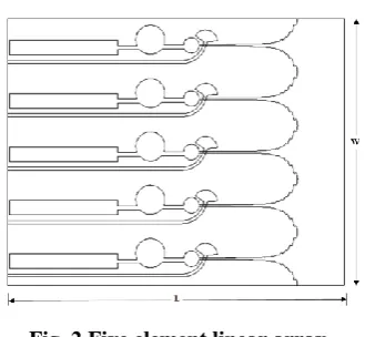
The design of the modified Vivaldi radiator is shown in Fig.1. Modifications with respect to the earlier reported papers are the inclusion of two circular cavities & an open circuited rectangular stub. Also the exponential taper characteristic of the conventional Vivaldi antenna has been modified with super imposition of a sinusoidal profile on exponential taper reported in our earlier paper [16]. This antenna has been taken as a reference antenna and it is used for designing a five element array. Also, with the central element excited, the return loss and the radiation patterns over 6-18 GHz is studied. The structure of the five element linear array is shown below Fig 2. The spacing between elements is 9.5 mm which is the required dimension to scan the array beam to ±45°.
Five Element Printed Modified Vivaldi Array
Covering 5.3 to 20 GHz
Taper length and taper rate are the two key parameters in taper design. The tapered slot line is designed with the following equations [5].
Y = C1 + C2 (1)
C1 = (y2-y1) / (e2RZ2–e1RZ1) (2)
C2 = (y1e2RZ2 –y2 e1RZ1) / (e2RZ2 – e1RZ1) (3)
Where (z1, y1) and (z2, y2) are end points of the exponential
curve, C1 & C2 are constants, and R is the exponential taper
[image:2.595.318.535.50.159.2]rate.
[image:2.595.53.273.209.278.2]Fig. 1.Antenna Geometry. The five element linear array is shown in Fig 2.
Fig. 2.Five element linear array.
III. PARAMETRICANALYSIS
Parametric analysis has been done using ANSYS HFSS software with the central element excited and the other antenna elements terminated. The basic design is derived from our earlier reference paper as already printed out above [18]. Key parameters affecting the VSWR of the antenna have been identified as follows:
- Length of the stub (L1)
- Exponential growth rate (a) - Sinusoidal amplitude (k) - Dielectric portion Length (L6)
- Width of the slot (W5)
With the above parametric variations, dimensions of the antenna have been optimized to obtain s11 of < 7.5 and satisfactory directional patterns from 5.3 to 18.0 GHz.
A. Variation of Length of the stub (L1)
The stub Length of L1 is changed from 17mm to 19.3mm.
[image:2.595.312.542.300.416.2]The return loss variation is significant at lower frequencies. However, no such variation is observed over 8.5 to 18 GHz. For an optimum value of L1=19.3mm a return loss of less than
Fig. 3.Return loss plot with length of the stub ‘L1’ variations.
B. Variation of Exponential growth rate (a)
[image:2.595.87.252.316.468.2]The growth rate is analyzing from 0.6 to 0.8 and the variations in the return loss plot are as shown in Fig.4. The other growth rate values have not met desired bandwidth requirement. The maximum bandwidth is achieved for a=0.6 over 6-18 GHz while the other values have peaks above -7.5 dB over 13.4-14.6 GHz from the plots.
Fig. 4.Return loss plot with growth rate ‘a’ variations.
C. Variation of Sinusoidal amplitude (k)
In this modified Vivaldi radiator, the exponential taper is super imposed by a sinusoidal function. The amplitude of the sinusoidal function ’k’ is changed from 0.1 to 0.4 and the return loss plots are as shown in Fig.5. K=0.2 is chosen as optimum value. Significant changes in return loss plot at the low frequency limit can be seen for other values of ‘k’.
Fig. 5.Return loss plot with sinusoidal amplitude ‘k’ variations.
D. Variation of Dielectric portion Length (L6)
The length of the dielectric portion of the antenna ‘L6’ is
varied from 2mm to 8mm and the suggestive variations in the return loss are observed over
[image:2.595.315.540.548.650.2]International Journal of Innovative Technology and Exploring Engineering (IJITEE) ISSN: 2278-3075, Volume-8 Issue-9, July 2019
[image:3.595.312.542.48.164.2]of L6 is 8mm for maximum bandwidth.
Fig. 6.Return loss plot with dielectric portion length ‘L6’ variations.
E. Variation of the slot Width (W5)
The slot width ‘W5’ has significant effect on return loss. It
[image:3.595.56.282.69.174.2]has been varied from 0.1mm to 0.3mm and the corresponding S11 curves are as shown in Fig.7. A slot width of 0.3mm is optimum.
Fig. 7.Return loss plot with slot width ‘W5’ variations.
IV. RESULTS
Variation of return loss, gain, radiation patterns and scanning over 5-18 GHz are studied using HFSS software and the results obtained are presented below. The optimized dimensions are arrived at from the parametric studies of central element only excited and other elements terminated and these are given in table I.
TABLE I. OPTIMUM DIMENSIONS
Parameter Dimension
(in mm)
L 60.0
W 9.5
L1 19.3
L6 8.0
W5 0.3
a 0.6
K 0.2
A. Return Loss
[image:3.595.314.542.262.391.2]A return loss of -7.5 dB is obtained over 5.3 to 20 GHz for the central element excitation in array environment and is shown in the Fig.8.
Fig. 8.Frequency vs.Return loss.
B. Active VSWR
[image:3.595.56.281.292.405.2]For the central element excitation in array environment the active VSWR of less than 2.5 over 5.4 to 18GHz has been obtained as shown in the Fig.9.
Fig. 9.Frequency vs. Active VSWR.
C. Gain
Frequency vs. Gain plot over the frequency range 6-18 GHz is shown in Fig.10 and gain at 18 GHz is 6.3 dB
Fig. 10. Frequency vs. Gain.
D. Radiation Patterns
[image:3.595.314.544.463.576.2] [image:3.595.103.231.546.685.2](a) 5 GHz
(b) 6 GHz
(c) 10 GHz
(d) 14 GHz
(e) 16 GHz
[image:4.595.310.542.180.315.2](f) 18 GHz
Fig. 11. Radiation patterns for central element in a five element linear array.
E. Scanning of 8 element linear array
An 8 element array has been designed using HFSS
environment. The spacing between elements is 9.5 mm. The maximum scan angle of the antenna without grating lobes depends upon the spacing between the elements in terms of wavelength is given by [11],
d/λ ≤ 1/(1+sinϴs) (4)
Where, d is the distance between elements, ϴs is the
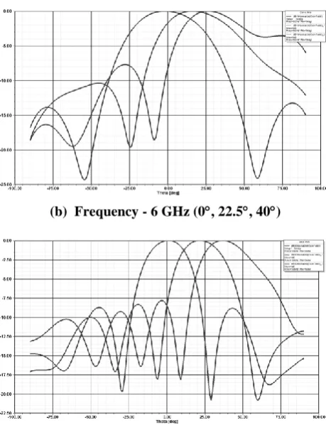
maximum scan angle. For the above spacing the maximum scan angle is 45°.The 8 element scanned radiation patterns over 5.3 GHz-18 GHz are shown in Fig.12 (a)-(e).
Fig. 12. (a) Frequency - 5.3 GHz (0, 22.5, 40)
(b) Frequency - 6 GHz (0, 22.5, 40)
[image:4.595.310.540.347.650.2]International Journal of Innovative Technology and Exploring Engineering (IJITEE) ISSN: 2278-3075, Volume-8 Issue-9, July 2019
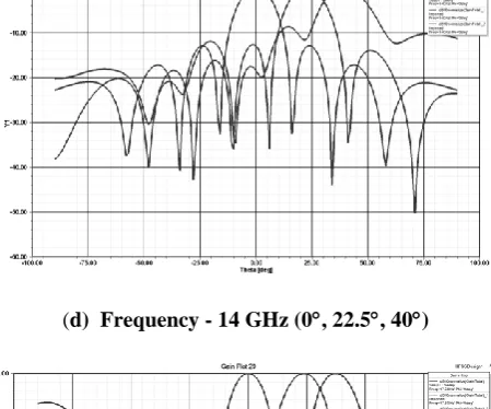
(d) Frequency - 14 GHz (0, 22.5, 40)
(e) Frequency - 17.5 GHz (0, 22.5, 40)
F. Proposed Robust Antenna Configuration
For making the antenna robust in environmental conditions, the proposed antenna will be immersed in rigid poly urethane foam of dielectric constant 1.4. A S11 of less than -7.5 dB over 4.8 to 23 GHz has been obtained. In this configuration, radiation patterns are satisfactory over 5 to 19 GHz.
[image:5.595.56.281.58.245.2]a) Return Loss
Fig. 13. Frequency vs. return loss
b) Gain
Fig. 14. Frequency vs. Gain.
c) Radiation Patterns
(a) 5 GHz
(b) 10 GHz
(c) 14 GHz
(d) 19 GHz
[image:5.595.55.284.497.671.2]oto
oto V. SPECIFICATIONSOFPROPOSEDANTENNA
The proposed antenna specifications arrived from HFSS simulations are as follows:
1. Frequency: 5.3 to 20 GHz 2. VSWR: < 2.5
3. HPBW (bore sight): 39.8 at 20 GHz, 158.28 at 5.3 GHz
4. Maximum Side lobe level: -12 dB 5. Number of elements in the array: 8 6. Scanning: 40° (5.3 to 17.5 GHz) 7. Power Gain: -3.0 to 6.3 dB
8. Cross polarization ratio: 20 dB min.
VI. CONCLUSION
Single modified Vivaldi antenna operating over 5.6 GHz to 20 GHz has been taken as reference antenna and a 5element array design has been done using HFSS software. Substantial modifications of the single antenna are required to take care of mutual coupling effects. A S11 of < -7.5dB has been obtained over 5.3-20 GHz for the central element excitation in the five element array and acceptable radiation patterns have been obtained over 5.3 to 18GHz. Also using this antenna, an 8 element linear array has been designed and scanning of beam has been studied. Satisfactory scanning to 40° from 5.3 GHz to 17.5 GHz has been observed.
ACKNOWLEDGMENT
The authors would thank Director, EMR &IP, and DRDO for the excellent support given by them. They would also like to thank Dr. A. Ratna Prasad, Principal and Dr. K. Sri Ramakrishna HOD, Dept. of ECE & V R Siddhartha Engineering College for their encouragement and support.
REFERENCES
1. B. Jacobs et al., “An improved Design for a 1-18 GHz double-ridged guide horn antenna,” IEEETrans. Antennas Propag., vol. 60, no.9, pp.4110-4118, Sep. 2012.
2. Z. Hu, Z.shen,W.Wu,, and J.Ju, “Low-profile log-periodic monopole array,” IEEETrans. Antennas Propag.,vol. 63, no. 12, pp.5484-5491, Dec.2015.
3. JihwanAhn, Seung Hun Cha, Seung Gook Cha, and Young Joong Yoon, “Compact spiral element for wideband beam- steering arrays,”IEEE Antennas and wireless propag., vol. 16.2017.
4. Kun Ma, Zhi Qin Zhao, Jiang Niu Wu, Mubarak S. Ellis and Zai Ping Nie, “ A Printed Vivaldi antenna with Improved Radiation Patterns by using two pairs of Eye shaped slots for UWB applications”, Progress in Electromagnetics Research, Vol.148, 63-71, 2014.
5. J. Shin and D. H. Schaubert, “A parameter study of stripline-fed Vivaldi notch-antenna arrays,” IEEE Trans. Antennas Propag., vol.47, no. 5, pp. 879–886, May 1999
6. K. Trott, B. Cummings, R. Cavener, M. Deluca, J. Biondi, and T.Sikina, “Wideband phased array radiator,” in Proc. IEEE Int. Symp. OnPhased Array Systems and Technology, 2003, pp. 383–386. 7. W.J.Otter, B.P.Pirollo, R.I.Henderson, R.A.Lewis," Multi-octave
BAVA radiating elements for use in modular phased array antennas", 2009 3rd European Conference on Antennas and Propagation, pp. 1324-1328, 2009.
8. Mike Stasiowski, Dan Schaubert, "Broadband array antenna" Proc. 2008, Antenna Applications Symposium, pp.72-59, Dec 2008, Monticello II.
9. Daniel. H. Schaubert, Tan-HuatChio, "Wideband Vivaldi arrays for large aperture antennas", Perspectives on Radio
astronomy-Technologies for Large Antenna arrays, Netherlands Foundation for Research in Astronomy-1999.
10. Junyeon Kim, Joonho So, Won Jang and ChangyulCheon, "Design of Wideband phased array antenna using Ridged Tapered Slot antenna", conference on Antennas and Propagation society international symposium 2006 IEEE.
11. C.B.Wyllie, G.M.Lewis and R.A.Lewis, "Dualpolarvivaldi antennas for phased arrays with wide angle scanning", 11th International Conference on Antennas and Propag, pp.672-676, 17-20 April 2001, UK.
12. Ibrahim T. Nassar and Thomas M. Weller, "A Novel method for Improving Antipodal Vivaldi Antenna Performance", IEEE Trans on Antennas and Propag, Vol.63, No.7, July 2015.
13. A. R. Bayat and R. Mirzakhani, “A parametric study and design of the balanced antipodal Vivaldi antenna (BAVA)”, PIERS Proceedings, Moscow, Russia, August 19-23, 2012.
14. K. Sneha and Dr. N. N. Sastry, "A Small Aperture Multi Octave Band Tapered Slot Radiator", Antennas and Propagation in Wireless Communications(APWC), 2017 IEEE -APS Topical Conference, Verona, Italy.
15. Bhagya lakshmi Munagoti, Lanka sree Lakshmi Sowjanya, Dr. N. N. Sastry, “Compact antipodal Vivaldi antenna with rectangular slots and shaping of flare to cover 6-18 GHz”, Electromagnetics 38.8(2018): 531-543.
16. G. NagaPavani, Ch. Lakshmi Prasanna, Dr. N. N. Sastry, “An ultra-wide band printed small aperture tapered slot phased array antenna covering 6-18 GHz”, IJET, Vol. 7, no.4, 2018.
AUTHORSPROFILE
Aparna Harshitha Chitturu was born in
Vijayawada, Krishna dist, AP on Nov 9th 1995, she obtained M.Tech with specialization in Commnication & Signal processing, V R Siddhartha Engineeering College, Kanuru, Vijayawada.
Miss M.Bhagya Lakshmi was born in Sattenapalli;
Guntur Dist. AP on May 12th 1991. she obtained B.Tech & M.Tech from JNTU Kakinada univ., she joined V.R.Siddhartha Eng College in 2015 and became Senior Research Fellow. She is present assistant Professor in V.R.S Engg. College, Vijayawada. She handled a major DLRL/DRDO project for 2 years. Her area of work has been in antennas and EW systems.
Dr. N. N. Sastry was born in Chirala; Prakasam Dist.