UNIVERSITI TEKNIKAL MALAYSIA MELAKA
REMOTE SENSING WALKER
This report submitted in accordance with requirement of the Universiti Teknikal Malaysia Melaka (UTeM) for the Bachelor Degree of Manufacturing Engineering
(Robotic and Automation) with Honours.
by
ABDUL ‘ALIM BIN ABDULLAH
iii
ABSTRACT
ABSTRAK
v
ACKNOWLEDGEMENTS
All Praise to Allah, the Lord of the Worlds, and prayers and peace be upon Muhammad Rasulullah S.A.W, His servant and Messenger. Alhamdulillah, with Allah blessings and guidance, I have completed this project successfully even though along the way, there are many hardship and obstacles.
First of all, I would like to acknowledge the inspiring professionalism and dedicated support of my thesis supervisor, Pn.Silah Hayati binti Kamsani, because willing to spend time, sharing experience, guidance and encouragement to accomplishing this project.
Her constant guidance and support during my thesis writing is invaluable to me and continuous direction and opinion regarding the flow of the project has an invaluable contribution to achieve the objectives of the project.
TABLE OF CONTENTS
Declaration i
Approval ii
Abstract iii
Abstrak iv
Acknowledgements v
Table of Contents vi
List of Figures xi
List of Table xiv
List of Abbreviations xv
1. INTRODUCTION 1
1.1 Problem Statement 2
1.2 Objective 2
1.3 Scope of Project 3
2. LITERATURE REVIEWS 4
2.1 Introduction 4
2.2 Walker 4
2.2.1 Push Walker 5 2.2.2 Lift Walker 5 2.2.3 Powered Walker having Integrated Parallel Bars 6 2.2.4 Powered Walker 7 2.3 Comparison Types of Walker 7 2.4 Mechanical Structure (Material) 8 2.4.1 Square Hollow Steel 8 2.4.2 Aluminum Profile 9 2.4.3 Comparison Types of Material 10
vii
2.5.1 DC Motor 10 2.5.1.1 Power Window Motor 11 2.5.1.2 Gear motor 11 2.5.2 Comparison Types of DC Motor 12 2.6 Control Circuit by Transistor 12 2.6.1 Forward and Reverse Circuit using Transistor 12 2.7 Electrical and Electronic Components 13
2.7.1 Relay 13
2.7.2 Speed Controller 14 2.7.2.1 Mechanical Speed Controller 14 2.7.2.2 Electronic Speed Controller 15 2.7.2.3 Comparison Types of Speed Controller 16
2.7.3 Battery 16
2.7.3.1 Lithium-ion 16 2.7.3.2 Lead-acid 17 2.7.3.3 Comparison Types of Battery 18 2.8 Mechanical Components 18 2.8.1 Rubber Wheel 18 2.8.2 Polyolefin Wheel 19 2.8.3 Comparison Types of Wheel 20 2.9 Remote control 20 2.9.1 RF (radio frequency) remote control 20 2.9.2 Wireless remote control 21 2.9.3 Comparison Types of Remote Control 22
2.10 Sensor 22
i. Computer Operation Codes (Opcode) 25 ii. Program Counter (PC) 26 iii. Instruction Register (IR) 26 iv. The Arithmetic Logic Unit (ALU) 27 v. Input/output Ports 28 2.11.2 Programmable Logic Controller (PLC) 28
2.11.3 Comparison Types of Programmable Controller 29
3. METHODOLOGY 30
3.1 Introduction 30
3.2 Problem Statement 30
3.3 Planning 31
3.4 Research about Project 32
3.5 Designing 32
3.6 Procurement 33
3.7 Fabrication and Testing 33 3.8 Improvement or Modification 34
4. DESIGN AND DEVELOPMENT 36
4.1 Introduction 36
4.2 Remote Control Circuit Design 36 4.2.1 2 Channel RF Remote Control Transmitter 36 4.2.2 2 Channel RF Remote Control Receiver 37 4.2.3 The Power Supply of RF Receiver 38 4.3 Forward and Reverse Motor Circuit 39
4.4 DC Motor Drive 40
ix
4.7 Mechanical Structure 46 4.7.1 Motor Bracket 46 4.7.1.1 Procedures to Develop the Motor Bracket 47 4.7.2 Switch Box Holder 49 4.7.2.1 Procedure to Develop the Switch Box Holder 49
4.7.3 Shaft 51
4.7.3.1 Procedures to Develop the Shaft 52 4.7.4 Castor Wheel Holder 53 4.7.4.1 Procedures to Develop the Castor Wheel Holder 53 4.8 Bill of Material (B.O.M) 56 4.9 Specification of Remote Sensing Walker 57
5. RESULT AND DISCUSSION 58
5.1 Result 58
5.1.1 EXPERIMENT 1: Smooth Surface and Rugged Surface 58 5.1.2 EXPERIMENT 2: Detection of Obstacle 61 5.1.3 EXPERIMENT 3: Hilly road (uphill) 65
5.2 Discussion 66
6. CONCLUSION 68
6.1 Conclusion 68
6.2 Suggestion For Further Works 69
LIST OF FIGURES
2.1 Push Walker 5
2.2 Lift Walker 6
2.3 Powered Walker having Integrated Parallel Bars 6
2.4 Powered Walker 7
2.5 Square Hollow Steel 9
2.6 Aluminum Profile 9
2.7 Power Window Motor 11
2.8 Gear motor 11
2.9 Forward and Reverse Circuit using Transistor 13 2.10 Electrical and Electronic Relay 14 2.11 Mechanical Speed Controller 15 2.12 Electronic Speed Controller 15 2.13 Lithium-ion battery 17 2.14 Lead-acid Battery 17
2.15 Rubber Wheel 19
2.16 Polyolefin Wheel 19
2.17 RF Remote Control 21 2.18 Wireless Remote Control 21 2.19 Inductive Proximity Sensor 23 2.20 Photoelectric Sensor 23
2.21 Microchip 25
2.22 Example of Program Counter 26 2.23 Instruction Registers 27 2.24 Block Diagram of ALU 27
2.25 I/O Pin 28
2.26 Programmable Logic Controller 29
xi
3.2 Methodology Flow Chart 35
4.1 Schematic of the Transmitter 37 4.2 Schematic of the Receiver 38 4.3 The Power Supply of RF Receiver 39 4.4 Forward and Reverse Motor Circuit 40
4.5 DC Motor Drive 41
4.6 Photoelectric Sensor Circuit 41 4.7 Placing the Electronic Component On the Strip Board 42
4.8 Soldering process 43
4.9 Cutting the Strip Board 43 4.10 Checking the Strip Board 43
4.11 Motor Bracket 46
4.12 Measurement Process 47
4.13 Cutting process 47
4.14 Filing Process 47
4.15 Drilling Process 48
4.16 Bending Process 48
4.17 Switch Box Holder 49 4.18 Measurement Process 49
4.19 Cutting Process 50
4.20 Filing Process 50
4.21 Bending Process 50
4.22 Drilling Process 51
4.23 Shaft 51
4.24 Cutting Process 52
4.25 Lathe Process 52
4.26 Castor Wheel Holder 53 4.27 Measurement Process 53
4.28 Cutting Process 54
4.30 Drilling Process 54
4.31 Bending Process 55
5.1 A human control the motion of the RSW manually 58 5.2 The motion of the RSW is control by remote control 59 5.3 Maximum Distance of the Photo-electric Sensor to Detect the
Obstacle
60
5.4 Angle and Maximum Distance of Photo-electric Sensor to detect the Obstacle
61
5.5 A human control the motion of RWS which when it detects the obstacle and automatically halts
62
5.6 The Motion of RWS Control by Using Remote Control which When It Detects the Obstacle and Automatically Halts
63
xiii
LIST OF TABLES
4.1 PIN Assignment of PIC 44
LIST OF ABBREVIATIONS
DC - Direct Current
MSC - Mechanical Speed Controller ESC - Electronic Speed Controller CPU - Central Processing Unit PC - Program Counter ALU - Arithmetic Logic Unit
1
CHAPTER 1
INTRODUCTIONHandicapped walker is a tool for disabled people who need additional support to maintain balance or stability while walking. According to Muiza, handicapped walker is available in sizes such as Pediatric (for children) or Bariatric (for overweight or obese persons). Handicapped walker is a good tool for those who are recuperating from leg or back injuries. It is also commonly used by persons who are having problems with walking or mild balancing problems. Basically, the handicapped walker has two main types; lift walkers or push walkers. Lift handicapped walkers are usually four points of ground contact with two of the points being rubber tips and the other two small rolling wheels. Beside that, push handicapped walkers have bigger tires and it has better the traction and easy to use.
1.1 Problem Statement
Traditionally, a handicapped walker is picked up and placed a short distance ahead of the user. The user then walks to it and repeats the process. If the elders or handicapped person have to move using manual walker, they must raised the walker step by step where it is very difficult and requires more energy to the user. Using the remote sensing walker, the users only need to push the switch at RF remote control and on the walker frame to move in various directions that are left, right, forward, and reverse. It also provides two photo-electric sensors and ability to detect the obstacle in front. This walker is easily park or return to the user where it only need the depressing of the switch at RF remote control and it also facilitate the user to go to anywhere without inconveniencing other people.
1.2 Objectives
i. To develop the remote sensing walker and should equipped with various types of component.
3
1.3 Scope of Project
CHAPTER 2
LITERATURE REVIEW2.1 Introduction
This chapter will present the literature reviews relevant to this project. It includes walker, mechanical structure, motor, and control circuit by transistor, electrical and electronic components, mechanical components, remote control, sensor, and programmable controller. The entire thing in this chapter must be considered to develop this project.
2.2 Walker
5 2.2.1 Push Walker
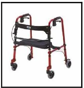
[image:21.612.254.398.277.428.2]Usually, push walkers are good for carpet area and has the big tire where it is better for movement. Push walkers have become so popular that walkers are now offered with many options. Some walkers have seats so the elders can take a break from the walking and sit for awhile. The push walkers are also more stable than the lift walkers. The reason for this is the bigger wheels and there is constant contact with the floor compare to intermittent contact with the floor when using the lift walker. Push walkers are also easily adjust to different floor surfaces .While the elder may have more contact with linoleum but when they do come in contact with carpeting it can be dangerous (1stSenior Care, 2007).
Figure 2.1: Push walker (1stSenior Care, 2007).
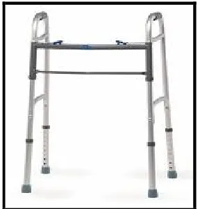
2.2.2 Lift Walker
Figure 2.2: Lift walker (Allegro Medical, 1997).
2.2.3 Powered Walker having Integrated Parallel Bars
This walker is an integrated powered walker and parallel bar to provide a stable and easy to use .This walker also to move forward according to a user need. The user can be controls the movement of this walker by depressing a switch. Beside, the user can also control the speed of this walker (Lathrop, 1996).
7 2.2.4 Powered Walker
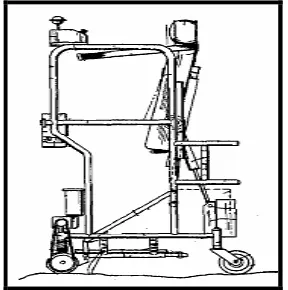
[image:23.612.254.398.222.367.2]This walker includes a frame assembly and has space for containing an operator in a standing position. When operators enter inside this walker, gate can be covered and opened. This gate purpose is to operator safety. This walker has a seat which can be adjustable either in horizontal or vertical direction. Beside that, this walker has a switch to control the movement either forward or reverse (Houston, and Metzger 1989).
Figure 2.4: Powered walker (Houston and Metzger, 1989).
2.2.5 Comparison Types of Walker
Types of walker Advantages Disadvantages
Push Walker Good for carpet area. More stable.
Easily adjust to different floor surfaces.
Easy loss of control Difficult to move at
rugged surface.
Lift Walker Lightweight and easy to lift.
Rigid dual sides brace design.
Not suitable for carpet area.
Powered Walker having Integrated Parallel Bars
Can move forward according user need. Have a switch for
movement.
Difficult to press the switch.
Lack of stability.
Powered Walker Has adjustable seat. Has a switch to control
the movement either forward or reverse.
Fairly heavy. Difficult to adjust
the seat in horizontal and vertical.
2.4 Mechanical Structure ( Material)
Mechanical structure is very important to develop the walker. Selection of material will influence the stability of walker. To obtain the best structure of walker, the materials that must be considered are:
2.4.1 Square Hollow Steel