INTELLIGENT SPYCAM WITH ROBOTIC ARM (ISRA)
HAZRUL FAZRIZAL BIN HILMAN
This report is submitted in partial fulfillment of the requirement for the award of Bachelor of Electronic Engineering (Industrial Electronics) With Honours
Faculty of Electronic and Computer Engineering Universiti Teknikal Malaysia, Melaka
UNIVERSTI TEKNIKAL MALAYSIA MELAKA
FAKULTI KEJURUTERAAN ELEKTRONIK DAN KEJURUTERAAN KOMPUTER
BORANG PENGESAHAN STATUS LAPORAN
PROJEK SARJANA MUDA II
Tajuk Projek : INTELLIGENT SPYCAM WITH ROBOTIC (ISRA)
………
Sesi Pengajian : 0 9 / 1 0
Saya: HAZRUL FAZRIZAL B HILMAN
……….. (HURUF BESAR)
mengaku membenarkan Laporan Projek Sarjana Muda ini disimpan di Perpustakaan dengan syarat-syarat kegunaan seperti berikut:
1. Laporan adalah hakmilik Universiti Teknikal Malaysia Melaka.
2. Perpustakaan dibenarkan membuat salinan untuk tujuan pengajian sahaja.
3. Perpustakaan dibenarkan membuat salinan laporan ini sebagai bahan pertukaran antara institusi pengajian tinggi.
4. Sila tandakan ( √ ) :
SULIT*
*(Mengandungi maklumat yang berdarjah keselamatan atau kepentingan Malaysia seperti yang termaktub di dalam AKTA RAHSIA RASMI 1972)
TERHAD** **(Mengandungi maklumat terhad yang telah ditentukan oleh
organisasi/badan di mana penyelidikan dijalankan)
TIDAK TERHAD
Disahkan oleh:
__________________________ ___________________________________
(TANDATANGAN PENULIS) (COP DAN TANDATANGAN PENYELIA)
Alamat: D/A Che Mahmood, Kg Banggol Judah, 18500 Machang, Kelantan.
iii
“I hereby declare that this report is the result of my own work and research
except for quotes and cited in the references.”
Signature :………..
Author : HAZRUL FAZRIZAL BIN HILMAN
iv
“I hereby declare that I have read this thesis and in my opinion this thesis is
sufficient in terms of the scope and quality for award of Bachelor of Electronic
Engineering (Industrial Electronic).”
Signature :………...
Supervisor’s Name : MISS ZARINA BT MOHD HOH
v
Dedicated to my family, especially Che Mahmood B Che Lah (father), and
Puan Mek Jah Bt Yusof (mother). Also to my Projek Sarjana Muda
vi
ACKNOWLEDGEMENT
First and foremost, I would like to express sincere gratitude and appreciation
to all people who have been involved either directly or indirectly and made it
possible for me to complete my PSM I and PSM II.
I am very indebted to my PSM supervisor, , Miss Zarina Bt Mohd Noh for
her guidance, support and especially her flexibility that she has given to me in order
to complete my project and research and for time to time will be a meaningful
memory and lesson for me for the future and my journey in this life.
Sincere appreciation also to UTeM staff especially the FKEKK Technicians
for their help and also to UTeM Librarians that helped me so much in finding books
and references related to my project and research.
Last but not least to others especially my family and friends who have given
me moral support in order to go through all the hard work and also for my mom and
dad blessing upon me.
Therefore, I end this acknowledgement with THANK YOU VERY MUCH in
vii
ABSTRACT
Design for intelligent SpyCam with Robotic arm (ISRA) is a project that to
developed a intelligent system that can remotely control all the system by using the
radio frequency (RF) signal. In this project there is much that should consider,
especially in the arm design. In this project, the basic concept of a ISRA it is using
transmitter and receiver to communicate between each system. The distance between
receiver and transmitter to sent the data is depend on the frequency of the RF. The
distance of the remote control is about 50m to 100 m, so it can be control in the wide
area. By using the wireless camera it can easily to monitor the area needed by the
user. The advantage of this project is, there is to reduce of the human power in the
hazardous place or in the dangerous area. It also can be use as a spy camera to view
viii
ABSTRAK
Reka bentuk untuk “intelligent SpyCam with Robotic arm (ISRA)”
merupakan satu projek yang yang boleh digunakan untuk mengawal semua system
yang dengan menggunakan frekuensi isyarat radio (RF) pada jarak jauh. Dalam
projek ini terdapat banyak yang perlu dipertimbangkan agar ianya menjadi satu
sistem yang sempurna, terutama sekali dalam reka bentuk lengan “arm”. Dalam
projek ini, konsep asas ISRA adalah dengan menggunakan isyarat pemancar dan
penerima untuk menghantar atau menerima setiap isyarat antara setiap system yang
digunakan. Jarak antara penerima dan pemancar bagi menghantar atau menerima
data bergantung frekuensi RF yang digunakan. Jarak kawalan jauh untuk
mengendalikan system didalam projek ini adalah 50m sehingga 100 m. Dengan
menggunakan kamera tanpa wayar ia secara langsung memudah untuk memantau
kawasan yang diperlukan oleh pengguna. Kelebihan projek ini ialah, ia dapat
mengurangkan penggunaan tenaga manusia dalam mengendalikan tempat atau
kawasan yang berbahaya. Ia juga boleh menggunakan sebagai sebuah kamera
ix
TABLES OF CONTENT
CHAPTER TITLE PAGE
PROJECT TITLE i
STATUS DECLARATION FORM ii
DECLARATION iii
APPROVAL iv
DEDICATION v
ACKNOWLEDGEMENT vi
ABSTRACT vii
ABSTRAK viii
TABLE OF CONTENT ix
LIST OF TABLES xii
LIST OF FIGURES xiii
LIST OF ABREVIATIONS xvi
LIST OF APPENDICES xvii
I INTRODUCTION 1
1.1 Introduction 1
1.2 Objective of this project 3
1.3 Scope of project 3
1.4 Problem Statement 4
II LITERATURE REVIEW 5
2.1 Background 5
2.2 Arm 6
2.2.1 Degrees of Freedom (DOF) 7
2.2.2 Denavit-Hartenberg (DH) Convention and
the Robot Arm Free Body Diagram (FBD) 7
2.2.3 Robot Workspace 9
2.2.4 Stand-Alone or Built-On Manipulators 12
2.2.5 Grippers 12
2.2.6 Shoulder Joint and Upper Arm 13
2. 2.7 Elbow and Forearm 13
x
2.4 Servo Motors 20
2.5 Remote Controller 22
2.5.1 The R/C Controller’s Interface 22
2.6 Applications 26
2.7 Common robot designs 27
2.7.1 Cartesian 27
2.7.2 Cylindrical 28
2.7.3 Spherical 28
2.7.4 Articulated 29
2.7.5 SCARA
(Selective Compliance Articulated Robot Arm) 30
III METHODOLOGY 31
3.1 Introduction 31
3.2 Flow and Gantt chart of methodology 32
3.3 Hardware design and development 34
3.3.1 Arm circuit 34
3.4 Electrical implementation 35
3.4.1 Voltage regulator 35
3.5 Servo motor control 36
3.6 Forward kinematics 37
3.7 Calculation of load torque 39
3.8 Camera attachment 40
3.9 The transmitter and receiver circuit
for the remote control 40
IV RESULT AND DISCUSSION 43
4.1
Introduction
43
4.2
Project result
44
4.3
Radio frequency (transmitter circuit)
44
4.3.1 Transmitter Design 45
4.3.2 Antenna 47
4.3.3 Signal analysis 48
4.4 Radio Frequency (receiver circuit)
51
xi
4.4.2 Data Processing 55
4.5
Arm robot circuit
57
4.6
Location of Camera 584.7
Voltage regulator (5V)
59
4.8
Hardware analysis
60
4.8.1 Gripper 61
4.8.2 Waist 62
4.9
Software analysis
63
4.9.1 Simulation test 63
V DISCUSSION AND CONCLUSION 66
5.1 Introduction 66
5.2 Discussion 67
5.3 Conclusion 68
5.4 Recommendation and project advantage 69
xii
LIST OF TABLES
NO TITLE PAGE
xiii
LIST OF FIGURES
NO TITLE PAGE
1.1 A family tree shows development of robots 2
2.1 4 DOF Robot Arm, three are out of plane 7
2.2. 3 DOF Robot Arm, with a translation joint 8
2.3 5 DOF Robot Arms 8
2.4 Assume that all joints rotate a maximum of 180 degrees 9
2.5 Now rotating that by the base joints another 180 degrees to get 3D 10
2.6 example of robot workspace 11
2.7 The gear transfer system used to actuate the shoulder of the revolute arm 13
2.8 Shoulder shaft detail. A. Completed shaft; B. Exploded view 14
2.9 A close-up view of the elbow joint 14
2.10 The completed arm with gripper attached 15
2.11 The clapper gripper A, assembly detail B top view 16
2.12 Construction detail of the basic two-pincher gripper 17
2.13 Hardware assembly detail of the pivot bar and fingers of the two-pincher
gripper. A. Assembled sliding joint; B. Exploded view 17
2.14 The finished two-pincher gripper, with fingertip pads and actuating cables 18
2.15 A commercially available plastic two-pincher robot arm and claw toy 18
2.16 A two-pincher gripper based on a homemade work drive system. A.
Assembled gripper B. Worm shaft assembly detail 19
2.17 Adding a second rail to the fingers and allowing the points to freely pivot
causes the fingertips to remain parallel to one another 19
xiv
2.19 The typical radio-controlled (R/C) servo motor 21
2.20 The internals of an R/C servo. The servo consists of a motor,
a gear train, a potentiometer, and a control circuit 21
2.21 pin out diagram for the Holtek HT-12E 23
2.22 Holtek HT-12E and HT-12D 24
2.23 Transmitter and Receiver 25
2.24 Example for the robot application 26
2.25 Examlpe for Cartesian robot 27
2.26 Examlpe for cylindrical robot 28
2.27 Examlpe for Spherical robot 28
2.28 Examlpe for articulated robot 29
2.29 Examlpe for SCARA robot 30
3.1 Flow Chart of PSM1 32
3.2 project Gantt chart 33
3.3 Arm circuit 34
3.4 Voltage regulator circuit 35
3.5 Servo motor control 36
3.6 Forward kinematics for cylindrical coordinate robot 37
3.7 Camera attachment to the arm robot 40
3.8 Transmitter circuit 41
3.9 Receiver circuit 42
4.1 Transmitter block diagram 44
4.2 Circuit testing on project board 45
4.3 Transmitter circuit On PCB 46
4.4 Antenna 47
4.5 Analysis of data output from the transmitter 49
xv
4.7 Analysis of RF output from the transmitter (after transmitted the signal) 50
4.8 Receiver block diagram 51
4.9 The Receiver on the PCB design 52
4.10 complete Receiver circuit 53
4.11 AM Envelope detector 54
4.12 AM Coherent detector 54
4.13 Integrated & Dump Filter 56
4.14 The arm 57
4.15 The camera 58
4.16 5V supply voltage circuit 60
4.17 Gripper 61
4.18 Waist of robot 62
4.19 Simulation of servo turning in +ve 90° position 64
4.20 Simulation of servo turning in 0° position 64
xvi
LIST OF ABREVIATIONS
DH - Denavit-Hartenberg
DOF - Degree Of Freedom
FBD - Free Body Diagram
FEC - Forward Error Correction
ISRA - Intelligent SpyCam With Robotic Arm
PCB - Printed Circuit Board
PIC - Peripheral Interface Controller
PWM - Pulse Width Modulation
RF - Radio Frequency
R/C - Remote Control
xvii
LIST OF APPENDICES
NO TITLE PAGE
A Programming language 71
B PIC16F873X Data Sheet 74
C RF-TX315 & RF-TX433 89
CHAPTER 1
INTRODUCTION
1.1 Background
At the dawn of the 20th century, an explosion of new scientific theories and
inventions led to the creation of a literature that sought to explore their implications
and a variety of possible futures. In the science fiction magazines of the 1920s and
1930s, the alien “bug-eyed monsters” were often accompanied by hulking robots.
These robots were often relentless in their attempts to carry out some sort of evil
plan. Robots also appeared in other media. Indeed, the word robot is first found in
the 1921 play Rossum’s Universal Robots by the Czech playwright Karel Capek.
Here and in Fritz Lang’s 1927 movie Metropolis, the robot took on a social
dimension, symbolizing the threat of automation to human livelihoods and
suggesting the relentless metronome-like pace of the industrial world. While many
writers caused people to fear robots, Isaac Asimov inspired a generation of engineers
to build them [1].
The development of the digital computer as well as sophisticated electronics
and control systems during the 1940s gave engineers the practical means to start
building real robots. Norbert Wiener, a mathematician whose interests ranged from
computers to game theory to neurology, provided in cybernetics a badly needed
theoretical framework for understanding communication, feedback, and control in
2
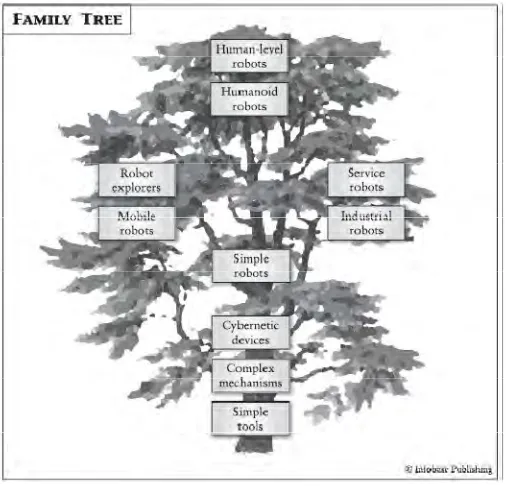
Building and programming a robot is a combination of mechanics,
electronics, and problem solving. What you're about to learn while doing the
activities and projects in This text will be relevant to "real world" applications that
use robotic control, the only difference being the size and sophistication. The
mechanical principles, example program listings, and circuits you will use are very
similar to, and sometimes the same as industrial applications developed by engineers
[image:19.612.210.463.221.464.2][2].
Figure 1.1: A family tree shows development of robots.
3
1.2 Objective of this project
1. To design and build a prototype system that can remotely control the system.
2. To find the suitable camera that can be used for this application.
3. To investigate the user interface that can easily be controlled by human.
4. To design small arm that can easily install to the project.
5. To investigate and research about the controlled unit using the PIC to control
all the system.
1.3 Scope of project
Below are the scopes of hardware and software for this project:
Hardware and Software section
a) For the user interface design, this system can be control by using the wireless
or radio frequency (RF). So before choosing the best interface, the
understanding both of the concept is very important.
b) By choosing the best resolution and suitable camera is to make sure this
project can function properly and at the same time can view higher resolution
video to the user.
c) The servo motor is a motor that is driven and controlled by an electrical pulse
train generated by digital device. Each pulse drives the servo motor by a
fraction of one Revolution, called the step angle.
d) Skype software or other software that can be used to view the video on the
computer.
e) The C language is used to design the PIC program. The PIC is module
provides a master Module controlled to control the robotic arm that install to
4
1.4 Problem Statement
The main problem in this project is to design the system that can carry the
camera and arm. At the same time, this system also can be control remotely by using
the wireless or radio frequency (RF). The PIC is used to make sure all the system can
function automatically. It also can be used as a spy in small area without being seen
CHAPTER II
LITERATURE REVIEW
2.1 Background
This chapter is intended to provide a review of the current literature relevant to
the topic of this project, and provides justification for the course of research pursued
according to the goals outlined in Chapter 1. This chapter is subdivided into three
sections: on kinematic modeling of robotic systems, methodologies for synthesizing
modular robotic manipulators, and random search methods. Each of these areas is
critical for the process of automatically creating, modeling and evaluating
6
2.2 Arm
The control of the arm is provided by the control box that came with the arm
except that the connections from the control box go through the microcontroller
which controls the outputs to a series of switches that turn on/off /switch direction of
the arm’s gear motors. The mode of operation is provided by a push-pull button and
a push button. When the push-pull button is off and the push button is not pressed,
the arm is in normal mode. When the push-pull button is on, the arm is in training
mode and when the push button is pressed, the arm is in playback mode. The arm
automatically reverts to normal mode after it has finished executing the trained
motion.
The ability to manipulate objects is a trait that has enabled humans, as well as
a few other creatures in the animal kingdom, to manipulate the environment. Without
arms and hands, it wouldn’t be able to use tools, and without tools it wouldn’t be
able to build houses, cars, robots. It makes sense, then, to provide arms and hands to
the robot creations so it can manipulate objects and use tools. It also can duplicate
human arms in a robot with just a couple of motors, some metal rods, and a few ball
bearings. Add a gripper to the end of the robot arm that has been creating to complete
arm-hand module. Of course, not all robot arms are modeled after the human
appendage. Some look more like forklifts than arms, and a few use retractable push
7
2.2.1 Degrees of Freedom (DOF)
The degrees of freedom, or DOF, are a very important term to understand.
Each degree of freedom is a joint on the arm, a place where it can bend or rotate or
translate. It can typically identify the number of degrees of freedom by the number of
actuators on the robot arm. Now this is very important. When building a robot arm
there have a few degrees of freedom allowed for the application, because each degree
requires a motor, often an encoder, and exponentially complicated algorithms and
cost [11].
2.2.2 Denavit-Hartenberg (DH) Convention and the Robot Arm Free Body Diagram (FBD) [8].
The Denavit-Hartenberg (DH) Convention is the accepted method of drawing
robot arms in FBD's. There are only two motions a joint could make: translate and
rotate. There are only three axes this could happen on: x, y, and z (out of plane).
Below I will show a few robot arms, and then draw a FBD next to it, to demonstrate
the DOF relationships and symbols. The Figure 2.1, Figure 2.2 and Figure 2.3 show
to us the Degree Of freedom (DOF) for the arm robot. Note that I did not count the
DOF on the gripper (otherwise known as the end effectors). The gripper is often
complex with multiple DOF, so for simplicity it is treated as separate in basic robot
[image:24.612.213.484.523.680.2]arm design.
![Figure 2.1: 4 DOF Robot Arm, three are out of plane [8].](https://thumb-us.123doks.com/thumbv2/123dok_us/107943.10021/24.612.213.484.523.680/figure-dof-robot-arm-plane.webp)
