Abstract: In the study of the state of deformation stress of multilayer doubly curved shell roof, the boundary conditions have a great effect. However, in the multilayer doubly curved shell roof, the change of each shell thickness also affects the deformation stress in the shell and the appearance of the cracks on the concrete shell is also different. In analytical studies, Vlasov, Ambarsumian, Thanh Huan Le, etc. have been implemented, but it is not clear that how the deformation stress in the shell is if having the effect of the change of each shell thickness. Therefore, in this paper, the author studies the change of the thickness of each shell to consider the effect of such change on the deformation stress in the shell and the phase of appearing the cracks in the concrete in the case the steel fiber concrete layer under the normal concrete layer with the boundary condition that the curved beam section is not changed by ANSYS numerical simulation software.
Keywords: steel fiber concrete; doubly curved shell roof; multilayer shell; ANSYS numerical simulation; effect of each shell thickness
1. INTRODUCTION
In the study of Lam et al [6] [7] by analysis and finite element method (via Sap2000 software), it studied the deformation stress of the multilayer doubly curved shell roof with the different boundary conditions based on the multilayer shell studies of Ambarsumian [4] [12] and Thanh Huan Le [14].
On the basis of the above studies, the author found that it is necessary to study the problem of the multi-layer doubly curved shell roof by experimental method which Lam [9] implemented and combined with ANSYS numerical simulation for the shell [10]. Through the study by experimental and ANSYS simulation method, it showed that the boundary conditions have a great effect on the deformation stress in the shell. In the multilayer shell, in addition to the effect of the boundary conditions on the deformation stress in the shell, the change of the thickness of each shell also affects the deformation stress, and they should be studied.
According to the study of the document [10], the two-layer doubly curved shell roof was experimented with a square plan of 3 × 3m. The lower layer is the B30 fiber concrete layer, the upper layer is the B20 normal concrete layer.
Revised Manuscript Received on April 15, 2019.
Thanh Quang Khai Lam, Department of Civil Engineering, Mien
Tay Construction University, 20B Pho Co Dieu street, ward 3, Vinh Long town, Vinh Long province, Vietnam ([email protected])
Thi My Dung Do, Department of Civil Engineering, Mien Tay
Construction University, 20B Pho Co Dieu street, ward 3, Vinh Long town, Vinh Long province, Vietnam ([email protected])
Curvature equation: 2 2 2 1 b y f a x f z (1) Where: f is the largest camber at the top of the roof:
2
1 f
f
f ; f1,f2 are the camber of the curved lines sliding in two directions; a, b are half the length of the side of the rectangular base of the shell.
a) Double-layer reinforced concrete doubly curved shell roof model
b) Make the mold and pour concrete
Effect of each shell thickness on deformation
stress and the ability for causing the cracks in
the multilayer doubly curved shell roof
[image:2.595.67.282.47.377.2]
c) The measuring device and strain gages on shell surface
Fig. 1. Model of two-layer curved shell roof experimented
Survey cases:
In order to study the thickness of each shell affecting the deformation stress state, we in turn investigated the thickness of each layer as (Table 1), with steel fiber concrete layer under the normal concrete layer:
Table 1: Two-layer shell thickness in three cases
Case 1 Case 2 Case 3 h1 + h2 (cm)
h1: the lower fiber
concrete layer h2: the upper normal
concrete layer
2 + 3
(cm) 2 + 2 (cm) 3 + 2 (cm)
Model selection: Finishing the finite element model by adjusting the input parameters from the experimental results of normal concrete, steel fiber concrete and steel fibers, including:
Selection of steel fiber model in concrete: three models are used: smeared model, embeded model and discrete model. Thus, in this study, steel fiber was dispersed in concrete so the use of the smeared model was reasonable.
Cracking modeling in concrete: Cracks in concrete are modeled in two basic forms: discrete model and smeared model. In this study, we are interested in the behavioral relationship between load and displacement without regard to crack shape, local stress. Therefore, in the study, select the smeared model for crack in concrete.
Choice of contact pattern between two concrete layers: In the calculation can be used interface element or thin-layer element to simulate the sliding contact between the two concrete layers.
Model building:
Element selection for the model: Concrete simulator element: SOLID65 element, Contact element: ANSYS offers "hard surfaces with soft surfaces" contact elements. The hard surface is called the "target" surface and is modeled with the TARGE170 element type for 3D contact. The surface of the deformation (soft surface) is called the "contact" surface, which is modeled by the CONTA173 element type.
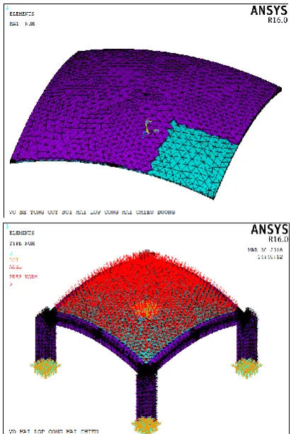
The meshing of the model: divided by the thickness of the shell is equal to the thinnest layer (ESIZE, ALL, hmin) and free mesh (MSHKEY, 0) with the 3D mesh geometry (MSHAPE, 1.3D).
Boundary and load condition of the modeling: Hard bonding with boundary beam. The distributed load on the upper surface of the casing at the nodes of the tetrahedron cubic grid (NSLA, R, 1), by P-weight distribution (SF, ALL, PRES, P).
Selection of normal concrete and steel fiber concrete models: using the Kachlakev model. Willam and Warnke's destructive standards.
Fig. 2. The meshing of the model, boundary beam and load of the model
2. RESULTS AND DISCUSSION
2.1. Results of deflection and stress of the ANSYS survey cases
[image:2.595.322.528.306.613.2]a) The deflection of the shell in case 1
b) Stress of the upper side x
c) Stress of the underside x
d) Stress of the upper side y
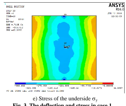
[image:3.595.318.538.60.244.2]e) Stress of the underside y
Fig. 3. The deflection and stress in case 1
The appearance phase of the cracks of the concrete: load P=14kN/m2=1400 kG/m2, stress 13.38kG/cm2, the first crack appears in the shell and along the boundary of the lower fiber concrete layer, the maximum deflection at the top of the shell is 0.17mm.
Case 2: h1 + h2 = 2 + 2 (cm)
a) The deflection of the shell in case 2
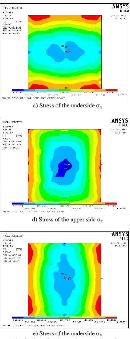
c) Stress of the underside x
d) Stress of the upper side y
[image:4.595.63.276.46.599.2]e) Stress of the underside y
Fig. 4. The deflection and stress in case 2
The appearance phase of the cracks of the concrete: load P=12.5kN/m2=1250 kG/m2, stress 13.9kG/cm2, the first crack appears in the shell and along the boundary of the lower fiber concrete layer, the maximum deflection at the top of the shell is 0.187mm.
Case 3: h1 + h2 = 3 + 2 (cm)
a) The deflection of the shell in case 3
b) Stress of the upper side x
c) Stress of the underside x
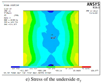
e) Stress of the underside y
Fig. 5. The deflection and stress in case 3
The appearance phase of the cracks of the concrete: load P=17.5kN/m2=1750 kG/m2, stress 12.76kG/cm2, the first crack appears in the shell and along the boundary of the lower fiber concrete layer, the maximum deflection at the top of the shell is 0.207mm.
2.2. Relationship diagram of load and deflection, load and deformation
With the load itself and the live load used on the shell roof according to the climate conditions in Vietnam: P=500 kG/m2
a) The deflection of the shell in survey cases
b) Stress x
c) Stress y
[image:5.595.312.545.50.165.2]Fig. 6. The deflection and stress in survey cases
Table 2: The deflection and stress of the two-layer shell in the survey cases
Position Position
(m) Case 1 Case 2 Case 3 (m) Case 1 Case 2 Case 3 Case 1 Case 2 Case 3 0 -0.071 -0.084 -0.069 0 -3.71 -4.28 -3.69 -3.66 -4.31 -3.65 0.75 -0.063 -0.074 -0.054 0.6 -3.27 -3.81 -3.15 -3.21 -3.83 -3.11 1.1 -0.039 -0.047 -0.031 1.2 -2.39 -2.84 -2.61 -0.94 -1.4 -0.93
1.5 0 0 0 1.5 0 0 0 0 0 0
Deflection (mm)
Stress x (kG/cm2)
Stress y (kG/cm2)
3. 3. CONCLUSION
▪ Case 1 and case 3: The total thickness is the same but the larger concrete fiber layer has smaller displacements and stress (this is understandable because the elastic modulus of the fiber concrete layer is larger than the normal concrete layer).
▪ The appearance phase of the cracks of the concrete: In case 3, the lower fiber concrete layer is thicker so the crack appears slower. In case 2 (minimum thickness), the crack appears earlier than other cases.
▪ Through ANSYS numerical simulation study, it is easy to simply determine the internal values, deflection, deformation, etc. on the entire shell surface and the simulation results are close to the actual work of structure which the real model experiments cannot be performed under certain conditions.
4. REFERENCES
1. ACI 544.1R-96 (1996), State-of-the-Art Report on Fiber
Reinforced Concrete.
2. ASTM A820-01 (2001), Standard Specification for Steel
Fibers for Fiber-Reinforced Concrete.
3. TCVN 5574 (2012), Concrete and reinforced concrete
structures-Design standard, Vietnamese standard.
4. Ambarsumian S.A. (1966), Some current aspects of the theory
of anisotropic layered shells. In Applied Mechanics Surveys.
5. Thanh Quang Khai Lam (2016), Some methods in calculating
stresses and deformations of reinforced concrete shell roof
structures. Vietnam Journal of Construction (ISSN
0866-0762), 6/2016, 165-168.
6. Thanh Quang Khai Lam, Thanh Huan Le (2016), Surveying
the stress-deformation of the laminated shell by anisotropic
shell theory and equivalent thickness diagram. Vietnam
Journal of Construction (ISSN 0866-0762), 8/2016, 190-194.
7. Thanh Quang Khai Lam, Thanh Huan Le, Tien Chuong
Nguyen (2016), Surveying the stress-deformation of the 5-layer shell roof by reinforced concrete with different boundary
conditions. Vietnam Journal of Construction (ISSN
0866-0762), 10/2016, 136-140.
8. Thanh Quang Khai Lam (2017), The research working
together of steel fiber concrete layer and normal concrete layer in double-layer concrete beams by experiment and by
ANSYS. Vietnam Journal of Construction (ISSN 0866-0762),
11/2017, 41-45.
9. Thanh Quang Khai Lam (2018), Research the
stress-deformation of double-layer reinforced concrete shell by
experiment. Vietnam Journal of Construction (ISSN
0866-0762), 3/2018, 58-61.
10. Lam Thanh Quang Khai, Do Thi My Dung (2019),
Stress-strain in multi-layer reinforced concrete doubly curved shell
roof. International Journal of Innovative Technology and
Exploring Engineering (IJITEE), ISSN: 2278-3075, Vol 8,
11. Vlasov V.Z. (1964), General theory of shells and its
applications in engineering. NASA TT F-99.
12. Aмбацумян С.А (1974), Общая Tеория анизоnтpопных
оболочек. Москва.
13. СП52-104-09 (2009), СТAЛЕФИБРОБЕТОННЫЕ
КОРСТРУКЦИИ, Москва.
14. Ле Тхань Хуан (1982), Напряжённо- деформированное
состояние Сборно и сборно – монолитных
железобетонных покрытий зданий в виде пологих
оболочек гауссовой положительной. kpивизны
применительно к климатическим и стройтельным