Int. J. Electrochem. Sci., 14 (2019) 755 – 763, doi: 10.20964/2019.01.02
International Journal of
ELECTROCHEMICAL
SCIENCE
www.electrochemsci.org
BaCe
0.9Er
0.1O
3--NaCl-KCl Composite As Electrolyte for
Intermediate Temperature Solid Oxide Fuel Cells
Hongtao Wang*, Yan Han, Ruijuan Shi, Liangquan Sheng, Qingmei Guan, Junlong Liu*
School of Chemical and Material Engineering, Fuyang Normal College; Anhui Provincial Key Laboratory for Degradation and Monitoring of Pollution of the Environment, Fuyang 236037, China
*E-mail: [email protected], [email protected]
Received: 6 September 2018 / Accepted: 22 October 2018 / Published: 30 November 2018
In this study, BaCe0.9Er0.1O3- (BCEr10) powders were synthesized by the microemulsion method using
anhydrous alcohol and PEG as the cosurfactant and surfactant, respectively. BaCe0.9Er0.1O3--20
wt%NaCl-KCl (BCEr10-NaCl-KCl) composite was also synthesized by heating the BCEr10 with binary NaCl-KCl. The physical chemistry changes in crystal phase formation and the microstructure of BCEr10 were determined by thermal gravimetry analysis-differential scanning calorimetry (TGA-DSC) and transmission electron microscopy (TEM). The BCEr10 and BCEr10-NaCl-KCl were characterized by XRD and SEM. The results revealed that the dense BCEr10-NaCl-KCl composite electrolyte was formed at a low temperature of 800 oC. The electrical conductivity was calculated from the AC impedance result.
The log ~ log (pO2) plot result indicated that the composite is almost a pure ionic conductor. Finally,
the optimum performance of BCEr10-NaCl-KCl was obtained with a highest power density of 413 mW·cm-2 at 700 °C.
Keywords: Composite electrolyte; BaCeO3; Molten salt; Fuel cell; Conductivity
1. INTRODUCTION
Perovskite oxides, such as SrCeO3, BaCeO3 and BaZrO3 which exhibit significant proton
conductivity, have attracted great attention due to their extensive applications as hydrogen pumps, gas sensors, and as electrolytes for intermediate temperature fuel cells [1-2]. Moreover, BaCeO3-based
ceramics show high conductivities compared to SrCeO3 and BaZrO3 and are a promising alternative
°C) [3-5]. However, this method will lead to inhomogeneous structures in the samples obtained. Generally, nanosized, homogeneous powders with high purity can be synthesized by using wet chemical methods, such as sol-gel, citrate-nitrate combustion, chemical precipitation and the microemulsion method [6-9].
Intermediate temperature solid oxide fuel cells could have many advantages, such as extending selectivity of components, reduce the manufacturing cost and improving persistent stability etc. [10-12]. Therefore, alternative composite electrolytes with high ionic conductivities have become a research hot spot. The main strategies are to film the high temperature proton conductors (HTPC) or to construct an inorganic-inorganic composite electrolyte [13-21]. Kjølseth et al. used a BaZrO3-based high temperature
proton conductor film to carry out efficiently a methane dehydroaromatization reaction [13]. Liu et al. combined a high temperature proton conductor, BaCe0.7In0.3O3−δ, with an ionic conductor,
Gd0.1Ce0.9O2−δ, to study the intermediate temperature fuel cell of the composite electrolyte [16]. Marques
et al. investigated ceria-carbonate composite electrolytes which have excellent intermediate temperature electrical performance [18-19]. And Park et al. and Huang et al. reported that composite electrolytes of doped barium cerate-carbonate have excellent intermediate temperature fuel cell performance [20-21]. However, our previous results indicated that SrCe0.9Yb0.1O3--NaCl-KCl has higher fuel cell
performance than that of SrCe0.9Yb0.1O3--Li2CO3-K2CO3 [22]. And in our previous works, we
confirmed that the total conductivity of the SrCe0.7Zr0.2Eu0.1O3-α-NaCl-KCl [23] and SrCe0.9Eu0.1O3-α
-NaCl-KCl [24] composite electrolytes are higher than their counterparts, SrCe0.7Zr0.2Eu0.1O3-α and
SrCe0.9Eu0.1O3-α.
For additional insight into the structure and composition of BaCeO3-based ceramics’ dependence
on electrical conductivities, and there are few studies devoted to the utilization of erbium as dopants, we synthesized BaCe0.9Er0.1O3- (BCEr10) via the microemulsion method. The physical chemistry changes
and microstructure of BCEr10 were determined by TGA and TEM. A BaCe0.9Er0.1O3--20
wt%NaCl-KCl (BCEr10-NaCl-wt%NaCl-KCl) composite electrolyte was also prepared at a low temperature of 800 oC. The structural and electrical conduction behaviors of BCEr10 and BCEr10-NaCl-KCl were also investigated.
2. EXPERIMENTAL
BaCe0.9Er0.1O3- (BCEr10) powders were prepared via the microemulsion method [25]. Er2O3
was firstly dissolved in concentrated nitric acid under stirring and then mixed with an aqueous solution of Ba(NO3)2 and (NH4)2Ce(NO3)6 in a stoichiometric molar ratio. A certain amount PEG, anhydrous
alcohol and cyclohexane were added to the above solution to form the microemulsion A. The microemulsion B was obtained by adding (NH4)2CO3-NH4OH to the mixture of anhydrous alcohol, PEG
and cyclohexane. The solution concentration of A and B was 0.05 g/mL. Finally, the microemulsion B was dripped into A. The precursor was calcined at 1200 °C and 1550 °C for 6 h, respectively.
The NaCl-KCl (mole ratio, 1:1) molten salt was obtained by calcining twice at 720 °C [26]. BaCe0.9Er0.1O3- and NaCl-KCl powders (weight ratio, 80:20) were then mixed and ground thoroughly.
°C for 2 h, the BaCe0.9Er0.1O3--20 wt% NaCl-KCl (BCEr10-NaCl-KCl) composite electrolyte was
obtained.
TGA-DSC measurements of BCEr10 were carried out in a nitrogen atmosphere from room temperature up to 1000 °C with a heating rate of 15 °C·min-1. The particle size and morphology of the BCEr10 precursor powder was examined using TEM. The crystalline phases of BCEr10 and BCEr10-NaCl-KCl were characterized by X–ray diffraction (XRD). The surface and cross-section characteristics of BCEr10 and BCEr10-NaCl-KCl were investigated by scanning electron microscopy (SEM).
The conductivities of BCEr10-NaCl-KCl composite electrolyte were evaluated with a CHI660E electrochemical analyzer in air at 400–700 °C. 20 % Pd-80 % Ag was used as electrodes by painting the paste onto both surfaces (area: 0.5 cm2) of the BCEr10-NaCl-KCl composite electrolyte pellet and connected with silver wires. In order to explore the ionic conduction under the different pO2, log as a
function of log (pO2) plot was measured at 700 °C [22]. In addition, the performance of a H2/O2 fuel cell
based on BCEr10-NaCl-KCl was also measured.
3. RESULTS AND DISCUSSION
[image:3.596.201.440.356.597.2]
0 200 400 600 800 1000
40 60 80 100 -5 0 5 10 15 20
Heat
Flo
w (W
/g
)
Temperature / oC
Weig
ht(%)
[image:4.596.170.453.74.288.2]Weight(%) Heat Flow (W/g)
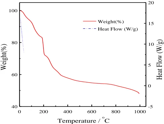
Figure 2. TGA-DSC curve of the BCEr10 precursor powder in nitrogen up to 1000°C.
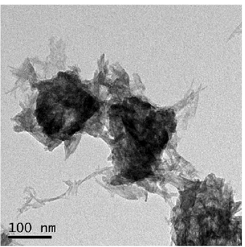
The TEM graph of the BCEr10 precursor powder by the microemulsion method is shown in Fig.1. Fig.1 indicates that the particle size of the BCEr10 is 80-120 nm, and they are generally agglomerated [27].
The TGA-DSC curve of the BCEr10 precursor powder up to 1000 °C at the heating rate of 15 °C·min-1 in a nitrogen atmosphere is shown in Fig. 2. The weight begins to decrease at about 40 °C and
has a weight loss of 5 % up to 90 °C with a weak endothermic peak which is ascribed to the adsorbed water of the BCEr10 precursor [28]. The DSC curve has an endothermic peak between 150 °C and 230 °C and the weight loss rate increases around 200 °C which is attributed to the loss of organic compounds [29]. The first calcined temperature is fixed at 1200 °C because there is also a slight weight loss around 1000 °C.
20 30 40 50 60 70
(4 20 ) (0 22 ) (2 11 ) BCEr10-NaCl-KCl
BCEr10 1550 oC
BCEr10 1200 oC
▽ ▽ NaCl ▽ ▼ ▼ KCl ▼ BaCeO
3 85-2155
NaCl 88-2300
KCl 75-0296
2/ o
Inte
nsit
y/a
[image:4.596.181.436.529.727.2].u.
Fig. 3 shows the XRD of BCEr10 and BCEr10-NaCl-KCl powders together with the standard data of BaCeO3 (JCPDS 85-2155), NaCl (JCPDS 88-2300) and KCl (JCPDS 75-0296). The XRD
patterns of BCEr10 indicate that both samples are single-phase orthorhombic BaCeO3 structures without
any obvious impurity phase after being calcined at 1200 °C and 1550 °C, respectively. The peaks at 2θ angles of 28.66º, 40.95º and 50.82º can be assigned to the (211), (022) and (420) crystal planes of BaCeO3 (JCPDS 85-2155), correspondingly. It can be seen from Fig. 3 that the BCEr10-NaCl-KCl
composite shows the same diffractions which are identified for the orthorhombic BaCeO3 phase, NaCl
[image:5.596.101.498.366.681.2]phase and KCl phase are also observed in the BCEr10-NaCl-KCl composite. The results of XRD indicate that there are two phases of BCEr10 and inorganic salts, which was the same as our previous studies [22–24].
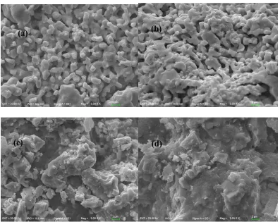
The surface and cross-section SEM morphologies of the BCEr10 pellet are displayed in Fig. 4(a,b). Fig. 4(a,b) shows most of the BCEr10 grains fused together. However, the grain boundary is not completely formed and the density is not high enough. The external and cross-sectional SEM morphologies of BCEr10-NaCl-KCl pellet are also shown in Fig. 4(c,d). The images reveal that the surface is completely covered with inorganic salts, molten inorganic salts are good for physical changes with BCEr10 particles to link each other and form a crackless three-dimensional structure [23–25].
Fig. 5 shows the temperature dependences of BCEr10-NaCl-KCl conductivity from 400 to 700 °C in air. From the plot of log (T) ~ 1000 T-1, the conductivity increases with the temperature increase. But the temperature dependences of KCl conductivity are non-linear and BCEr10-NaCl-KCl exhibits a sharp increase in conductivity at a temperature 600 °C, which is about 50 °C lower than the melting point of NaCl-KCl. The highest conductivity in air reaches 0.23 S·cm-1 at 700 °C. This may be attributed to the change of the conduction mechanism, due to the change of the concentration of the effective charge carriers [30–32].
1.0 1.1 1.2 1.3 1.4 1.5 -1
0 1 2 3
BCEr10-NaCl-KCl 400-700 oC
1000 T-1 / K-1
Lo
g(
T/
Sc
m
-1 K)
Figure 5. The log (T) ~ 1000 T-1 plot of the BCEr10-NaCl-KCl in air from 400 to 700 °C.
-20 -15 -10 -5 0
-1.0 -0.8 -0.6 -0.4 -0.2 0.0
BCEr10-NaCl-KCl 700 oC
Log( pO
2 / atm )
Log(
/ Scm
-1 )
[image:6.596.172.436.490.691.2]
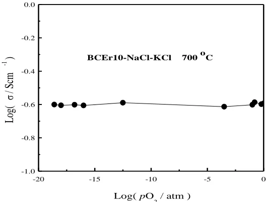
To investigate ionic conduction of the BCEr10-NaCl-KCl, the variation of the conductivity with the partial pressure of oxygen in the range of pO2 = 10-20~1 atm was measured. It can be seen from Fig.
6 that the conductivities are almost independent on pO2 at 700 °C. This result indicates that the composite
electrolyte is almost pure ionic conductors, which agrees with previous reports of BaCeO3-based
materials [6,8,11].
The performance of single cell based on a BCEr10-NaCl-KCl electrolyte (thickness = 1.15 mm) was tested by using hydrogen as the fuel and oxygen as the oxidant at 700 °C. The I-V and power density curves are shown in Fig. 7. As can be seen from Fig. 7, the open circuit voltage (OCV) is as high as 1.08 V which confirms that the composite electrolyte has a high density [25]. It is concluded that NaCl-KCl melted and filled the pores inside the composite and made it quite dense at 700 °C.
0.0 0.3 0.6 0.9 1.2
P
/ (mW
c
m
-2 )
Vo
lta
ge
/
V
Current density / (mA cm-2)
0 300 600 900
0 100 200 300 400 500
[image:7.596.163.448.257.452.2]BCEr10-NaCl-KCl 700 oC
Figure 7. I-V and I-P curves for H2/O2 fuel cell based on BCEr10-NaCl-KCl at 700 °C.
The fuel cell based on BCEr10-NaCl-KCl exhibits good cell performance and gives a power output density of 413 mW·cm-2 at 700 °C. The result is much better than the best performances ever reported for intermediate temperature SOFCs based on SrCe0.9Eu0.1O3-α-NaCl-KCl of 207 mW·cm-2 [24]
and SrCe0.9Gd0.1O3-α-NaCl-KCl of 215 mW·cm-2 [33] at 700 °C.
4. CONCLUSIONS
In this study, a novel BaCe0.9Er0.1O3- (BCEr10) electrolyte was prepared by a microemulsion
method. The TEM result indicates that the BCEr10 particle is 80-120 nm. The TGA-DSC curve shows that the formation of the orthorhombic BaCeO3 phase is higher than 1000 °C. The XRD patterns indicate
that there was no reaction between BCEr10 and NaCl/KCl. The highest conductivity observed for BaCe0.9Er0.1O3--20 wt%NaCl-KCl (BCEr10-NaCl-KCl) was 0.23 S·cm-1 at 700 °C. The H2/O2 fuel cell
ACKNOWLEDGEMENTS
This work was supported by the National Natural Science Foundation (No. 51402052, 21807012) of China, the Natural Science Project of Anhui Province (No. KJ2018A0337, KJ2017ZD28, KJ2016A548, 2015zy037, zdyj-0081), Sichuan Provincial Key Laboratory Foundation (No. hx2015005), Excellent Youth Foundation of Anhui Educational Committee (No. gxyq2018046), Horizontal cooperation project of Fuyang municipal government and Fuyang Normal College (No. XDHX2016019, XDHX2016002, XDHXTD201704, XDHX201739), Excellent Youth Foundation of Fuyang Normal College (rcxm201805) and Foundation of Anhui Provincial Key Laboratory for Degradation and Monitoring of Pollution of the Environment (2019HJJC01ZD).
References
1. H. Iwahara, T. Esaka, H. Uchida and N. Maeda, Solid State Ions, 3/4 (1981) 359.
2. Y. Yang, H. Hao, L. Zhang, C. Chen, Z. Luo, Z. Liu, Z. Yao, M. Cao and H. Liu, Ceram. Int., 44 (2018) 11109.
3. E. Pikalova and D. Medvedev, Int. J. Hydrogen Energy, 41 (2016) 4016. 4. S. Y. Bae, J.-Y. Park and H.-T. Lim, Electrochim. Acta, 236 (2017) 399.
5. H. Sun, S. Zhang, C. Li, B. Rainwater, Y. Liu, L. Zhang, Y. Zhang, C. Li and M. Liu, Ceram. Int., 42 (2016) 19231.
6. N. Danilov, E. Pikalova, J. Lyagaeva, B. Antonov, D. Medvedev, A. Demin and P. Tsiakaras, J. Power Sources, 366(2017) 161.
7. J. Xiao, L. Chen, H. Yuan, L. Ji, C. Xiong, J. Ma and X. Zhu, Mater. Lett., 189 (2017) 192. 8. J. Lyagaeva, G. Vdovin, L. Hakimova, D. Medvedev, A. Demin and P. Tsiakaras, Electrochim.
Acta, 251 (2017) 554.
9. G. S. Reddy and R. Bauri, J. Alloy Compd., 688 (2016) 1039.
10.G. L. Liu, W. Liu Q. Kou and S. J. Xiao, Int. J. Electrochem. Sci., 13 (2018) 2641.
11.Y. N. Chen, T. Tian, Z. H. Wan, F. Wu, J. T. Tan and M. Pan, Int. J. Electrochem. Sci., 13 (2018) 3827.
12.C. Xia, Z. Qiao, C. Feng, J. Kim, B. Wang and B. Zhu, Materials, 11(2018) 40.
13.S.H. Morejudo, R. Zanón, S. Escolástico, I. Yuste-Tirados, H. Malerød-Fjeld, P.K. Vestre, W.G. Coors, A. Martínez, T. Norby, J.M. Serra and C. Kjølseth, Science, 353 (2016) 563.
14.L. Bi, E.H. Da'as and S.P. Shafi, Electrochem. Commun., 80 (2017) 20.
15.C. Duan, J. Tong, M. Shang, S. Nikodemski, M. Sanders, S. Ricote, A. Almonsoori and R. O'Hayre, Science, 349 (2015) 1321.
16.F. Liu, J. Dang, J. Hou, J. Qian, Z. Zhu, Z. Wang and W. Liu, J. Alloy Compd., 639 (2015) 252. 17.K.-Y. Park, T.-H. Lee, S. Jo, J. Yang, S.-J. Song, H.-T. Lim, J.H. Kim and J.-Y. Park, J. Power
Sources, 336 (2016) 437.
18.A.I.B. Rondao, S.G. Patricio, F.M.L. Figueiredo and F.M.B. Marques, Int. J. Hydrogen Energ., 39 (2014) 5460.
19.N.C.T. Martins, S. Rajesh and F.M.B. Marques, Mater. Res. Bull., 70 (2015) 449.
20.K.-Y. Park, T.-H. Lee, J.-T. Kim, N. Lee, Y. Seo, S.-J. Song and J.-Y. Park, J. Alloy Compd., 585 (2014) 103.
21.Y. Hei, J. Huang, C. Wang and Z. Mao, Int. J. Hydrogen Energy, 39 (2014) 14328. 22.W. Zhang, M. Yuan, H. Wang and J. Liu, J. Alloy Compd., 677(2016) 38.
23.R. Shi, J. Liu, H. Wang, F. Wu and H. Miao, Ceram. Int., 43 (2017) 16931.
24.R. Shi, J. Liu, H. Wang, F. Wu, H. Miao and Y. Cui, Int. J. Electrochem. Sci., 12 (2017) 11594. 25.Y. Guo, B. Liu, Q. Yang, C. Chen, W. Wang and G. Ma, Electrochem. Commun., 11 (2009) 153. 26.X. Liu, N. Fechler and M. Antonietti, Chem. Soc. Rev., 42 (2013) 8237.
28.A. Matsuda, S. Oh, V.H. Nguyen, Y. Daiko, G. Kawamura and H. Muto, Electrochim. Acta, 56 (2011) 9364.
29.M.T. Soo, N. Prastomo, A. Matsuda, G. Kawamura, H. Muto, A.F.M. Noor, Z. Lockman and K.Y. Cheong, Appl. Surf. Sci., 258 (2012) 5250.
30.S. Shawuti and M.A. Gulgun, J. Power Sources, 267(2014) 128.
31.B. Zhu, S. Li and B.E. Mellander, Electrochem. Commun., 10 (2008) 302.
32.C. Xia, Y. Li, Y. Tian, Q. Liu, Y. Zhao, L. Jia and Y. Li, J. Power Sources, 188(2009) 156. 33.L. Sun, H. Wang, L. Sheng and H. Li, Int. J. Electrochem. Sci., 12 (2017) 9689.